
 ?Mathematical formulae have been encoded as MathML and are displayed in this HTML version using MathJax in order to improve their display. Uncheck the box to turn MathJax off. This feature requires Javascript. Click on a formula to zoom.
Abstract
Presented in this article is a new method to measure the film thickness in a rolling bearing running under starved conditions, such as in grease-lubricated bearings, using the electrical capacitance method. The method was used to study the impact of speed on film thickness. Results show that fully flooded conditions prevail at lower speeds where the film thickness increases with increasing speed. At higher speeds, where grease-lubricated bearings run under starved lubrication conditions, this increase is less pronounced. At even higher speeds, the film thickness becomes almost independent of the speed.
Introduction
There are more than 18 billion rolling element bearings currently in use. By far, most of them are grease lubricated (Citation1). Bearing life is determined by fatigue life and is reduced when lubrication is ineffective (Citation2, Citation3). This reduction does not takes place when the contacting surfaces are fully separated, preventing metal-to-metal contact. For fully flooded conditions the (elastohydrodynamic, EHL) film thickness can be predicted using Hamrock and Dowson’s equations (Citation4, Citation5) or Nijenbanning’s equation (Citation6). These fully flooded conditions typically occur in oil-lubricated bearings. In the case of grease lubrication, at medium and higher speeds, starvation occurs and the films can no longer be predicted using these equations. The existing models for starved lubrication, such as those from Wedeven et al. (Citation7), Damiens et al. (Citation8), Hamrock and Dowson (Citation9), and Van Zoelen et al. (Citation10), all require some measure of the volume of oil in the inlet as input, an unknown for grease-lubricated bearings. The full problem is very complex and the development of models can be greatly supported by having accurate film thickness measurements.
Early studies on grease film thickness by Poon (Citation11), Wilson (Citation12), and Dyson and Wilson (Citation13) using twin-disc machines showed that grease forms a thicker film than its base oil at the beginning of operation but the film thickness decreases quickly over a period of time before stabilizing. Point contact measurements and model calculations by Jonkisz and Krzeminski-Freda showed that the pressure distribution and the shape of a grease film can be predicted using the base oil properties (Citation14). Åstrom et al. (Citation15) showed that the film thickness inside the Hertzian contact is not uniform and were the first to show that thickener fibers pass through the EHL contact under fully flooded conditions. This was confirmed by Cann and Spikes (Citation16).
The studies by Booser and Wilcock (Citation17), Baker (Citation18), and Wikström and Jacobson (Citation19) showed that the film thickness in a grease-lubricated bearing is determined by the lubricant feed and loss mechanism. They listed various replenishment mechanisms such as grease bleed, centrifugal force–induced flow, and capillary forces. The loss mechanisms identified are pressure-induced side flow, centrifugal force–induced side flow, evaporation, cage scraping, oxidation, drop loss, and polymerization (Citation1). These replenishment mechanisms were studied for single point contacts and for full bearings (Citation20–24). Today these replenishment mechanisms are yet to be fully understood.
In 1974, Chiu postulated that replenishment mainly occurs in between the balls in a bearing, denoted by “out of contact replenishment”. He developed a model based on surface tension, which he used to predict the onset of starvation (Citation25). In Chiu’s model, it is assumed that there is sufficient oil available from the ridges along the track. Guangteng and Spikes (Citation26) studied film thickness under extremely starved conditions, denoted by “parched lubrication,” and showed that, at high speeds, the film thickness levels off. They built a model in which the film thickness is a function of the disjoining pressure. They concluded that replenishment in the thick-film regime is dominated by surface tension and that the disjoining pressure inhibits the complete collapse of the film.
Recently, Nogi (Citation27, Citation28) simulated the starved EHL point contact to study the effect of capillary number on starved film thickness, considering the unevenly distributed oil film in the inlet of the contact. In their simulations, instead of assuming the inlet meniscus as a straight line as done by Hamrock and Downson, they used a Coyne-Elrod theory to obtain the inlet film thickness. The inlet meniscus position was evaluated based on the inlet oil film thickness using the Elrod algorithm. Fischer et al. (Citation29) derived a parameter to determine the transition to starved lubrication from fully flooded condition based on the capillary number and therefore the contact angle of the base oil. The authors found that starvation was controlled by the capillary number, a function of the base oil surface tension.
Single contact measurements may not properly include possible replenishment effects caused by preceding contacts or, in general, by the thin-film flow on all surfaces in a bearing such as described by Van Zoelen et al. (Citation30). These single contact measurements are very useful to understand some of the basics in grease-lubricated bearings. However, we have now reached a point where we can only achieve further understanding by studying the film thickness in the grease-lubricated bearing itself. The film thickness in a full bearing at ultra-low speeds was measured by Morales-Espejel et al. (Citation31). They found that the film thickness is significantly larger than that for base oil lubrication. For moderate speed conditions, Cen and Lugt (Citation32) reported that the relative film thickness follows a power law relation with the product of viscosity, speed, and half contact width.
To measure the film thickness in rolling bearings, the most suitable method currently available is the electrical capacitance method. The ball–ring interface resembles a parallel-plate capacitor where the capacitance is determined by the lubricant film thickness that separates the ball and the ring. The capacitance method was first used by Lewicki (Citation33) and then by Crook (Citation34), Dyson and Wilson (Citation13), and Wilson (Citation12). Later, the method was refined by including the capacitance formed outside the Hertzian zone. In this article, we call this the “outside capacitance.” Barz (Citation35) used a correction factor to compensate for this outside capacitance. Cen and Lugt (Citation36) used the calibration method developed by Wilson (Citation12), who neglected this effect. Jabloka et al. (Citation37–39) calculated the outside capacitance for fully flooded conditions for a single point contact as well as for the full bearing. In our work, we further developed their approach for starved contacts; that is where the contact is not fully flooded with lubricant. In addition, in our new method we do not need to know the dielectric constant of the lubricant. Finally, we do not need to make use of a density–pressure relationship.
We will first describe the new method and later employ it to study the film thickness in a grease-lubricated deep-groove ball bearing as a function of speed for three different temperatures. It was found that the film thickness at low speeds is similar to or higher than the film thickness from using just the base oil. Beyond a certain transitional speed, we will show that the film thickness is almost independent of speed.
Film thickness measurement using electrical capacitance
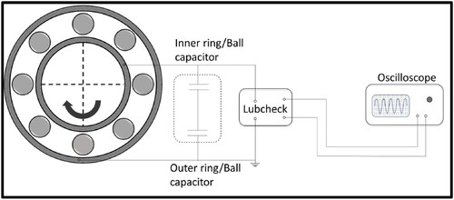
An in-house-made bearing test rig was used for measuring the film thickness. The electrical capacitance was measured using Lubcheck Mk3, a device developed by Heemskerk et al. (Citation40); see . Here, the test bearing is electrically isolated, the stationary outer ring is directly connected to the Lubcheck Mk3, and the rotating inner ring is connected through a mercury contact. The detailed description of the test rig is given by Cen and Lugt (Citation36). The relation between the Lubcheck output voltage Vcap and the electrical capacitance of the bearing reads
[1]
[1]
where Cref is a Lubcheck reference capacitance.
Figure 1. Schematic representation of the bearing with Lubcheck (Citation46).
In this article, all measurements were performed with a standard lithium hydroxystearate–thickened grease with a mineral oil with a viscosity of 100 and 10 cSt at 40 and 100C, respectively.
There are two commonly used methods to evaluate the film thickness in a bearing using the electrical capacitance method: (Citation1) the calibration curve, method developed by Dyson and Wilson (Citation13) (which was also used by Cen and Lugt (Citation36)) and (Citation2) a capacitance model method developed by Jablonka et al. (Citation37). Here, we review both because we will use components of each in our new method.
Method 1 by Wilson
Because the measured bearing capacitance is influenced by the outside capacitance, as discussed previously, and the dielectric constant of the oil is pressure dependent, obtaining the central film thickness from measurements is not straightforward. Wilson (Citation12) and, subsequently, Cen and Lugt (Citation36) made a calibration curve for a certain load by performing a speed sweep with base oil, during which they measured both the capacitance and the bearing temperature and then calculated the film thickness for each speed using Hamrock and Dowson’s fully flooded film thickness equation. This then gives a relation between film thickness and capacitance for a specific bearing load and speed. The Hamrock and Dowson film thickness equation is
[2]
[2]
where hc is the central film thickness (also subsequently rewritten as hff, where ff stands for fully flooded); Rx is the reduced radius in the x direction; U, G, and W are the dimensionless speed, material, and load parameters; and kd is the ellipticity parameter. The temperature was measured on the outer ring of the bearing, and for each speed the kinematic viscosity of the oil was calculated using Walther’s equation:
[3]
[3]
where B is a fluid-specific constant. For oil, B = 0.7. The constants c and K can be calculated from the known viscosities of the oil at two different temperatures via
[4]
[4]
[5]
[5]
The calibration for measuring the grease film thickness is done with oil. It is uncertain to what extent thickener will enter the contact and influence the dielectric constant. To compensate for this, Wilson (Citation12) added a small quantity of di-(2-ethylhexyl) sebacate to the mineral oil.
However, we have not used any additives to compensate for the dielectric constant because this difference was very low (about 10%), as well as to avoid any changes in the original grease properties.
The approach is simple and easy to use. However, one cannot distinguish between the film thickness on the outerring and inner ring with this method. In addition, there is no compensation in the calibration curve for the effect of starvation.
Method 2 by Jablonka et al.
In the above method from Wilson (Citation12), the test rig, including the bearing, was modeled as a single capacitor. Jablonka et al. (Citation37, Citation38) developed a more advanced electrical model of the bearing, with the work of Barz (Citation35) as a starting point, including the Hertzian contact capacitance, outside capacitance, and background capacitance. The outside capacitance is the contribution to the total capacitance of the gap between the ball and ring outside the Hertzian contact, denoted here by hgap. The background capacitance is the capacitance of the rig except for the contribution of the EHL contacts. This background capacitance is independent of the operating conditions of the bearing and can be regarded as constant.
For a purely axially loaded ball bearing with n balls, all balls are equally loaded and the film thickness between the balls and rings can be considered equal for all balls. The electrical circuit between the inner and outer rings therefore consists of n capacitors in parallel where each of these again consists of two capacitors in series, formed by the ball–inner ring contact and the ball–outer ring contact. The film thickness in the Hertzian contact is assumed to be uniform and each contact can therefore be simulated by a parallel-plate capacitor.
For a parallel-plate capacitor, the capacitance is given by
[6]
[6]
where ϵ0 is the permittivity constant
ϵoil is the dielectric constant of the dielectric material (for example, lubricating oil), A is the area of the capacitor plate, and h is the distance between the parallel plates.
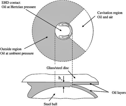
shows a single contact. It is evident that the total capacitance is not only due to the Hertzian contact region, but also includes the capacitance due to the outside regions.
Figure 2. Pictorial representation of a single point contact showing the flooded and cavitated regions around the Hertzian contact. Reproduced from Jablonka et al. (Citation37) with permission.
The equivalent electrical circuit for a ball bearing with a metal cage is shown in . For each ball, the ball–inner ring capacity is
[7]
[7]
and the ball–outer ring capacity is
[8]
[8]
where the subscripts Hertz and outside indicate the Hertzian and outside capacitances, respectively. For n number of balls, the inner ring capacity reads
[9]
[9]
and the outer ring capacity is
[10]
[10]
Figure 3. Equivalent electrical circuit showing capacitances at the ball–ring interfaces.
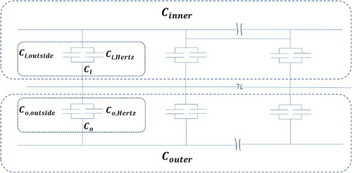
Because the inner and outer ring capacitances are in series, the equivalent/total capacitance of the bearing is given by
[11]
[11]
where Cbackground is the capacitance of the test rig itself, which can be assumed constant.
For a single contact they calculated the outside capacitance as
[12]
[12]
where, as illustrated in , Cflooded and Ccav are the flooded region capacitance and the cavitated region capacitance, respectively, given by
[13]
[13]
and
[14]
[14]
The integration limits Aflooded and Acav are calculated based on the following assumptions:
On the inlet side of the contact, capacitance was calculated up to the point where the separation of the surface is nine times the central film thickness assuming the fully flooded condition.
To calculate the capacitance on the side of the contacts, it was assumed that oil fills the gap between the ball and the bearing ring up to the shoulder.
In the cavitation region, the capacitance was calculated up to the distance where surface separation reaches nine times the central film thickness.
It is assumed that the central film splits into two equal halves, neglecting the effect of decompression at the outlet (see ). The Hertzian capacitance–film thickness relationship, from EquationEq. [6][6]
[6] , reads
[15]
[15]
where hc is the central film thickness and AHertz is the Hertzian contact area. The dielectric constant ϵoil at normal pressure and temperature was obtained from published values in the literature. Jablonka et al. (37) used pressure– and temperature–dielectric constant relationships to obtain the dielectric constant of the oil at higher pressure and temperature. The background capacity Cbackground, in EquationEq. [11]
[11]
[11] , was measured with a hybrid bearing (i.e., with ceramic balls). In their experiments, they used a single steel ball and the other balls were ceramic. They roughly estimated the film thickness using Hamrock and Dowson’s film thickness equation to calculate the outside capacitance and measured the background capacitance. The final film thickness was then obtained by considering the inner and outer ring capacitances in series, as done in EquationEq. [11]
[11]
[11] ; thus,
[16]
[16]
where
and
are the Hertzian contact area on the inner ring and outer ring, and
and
are outside capacitances of the ball–innerring and ball–outer ring contacts.
So far, all methods are calibrated by assuming fully flooded conditions. However, grease-lubricated bearings usually run under starved lubrication conditions, leading to a somewhat lower capacitance for the same film thickness. In the method by Jablonka et al. (Citation37, Citation38), the outside capacitance is overestimated if the bearings are running under starved lubrication.
The new method
The starting point of our new method is Jablonka et al.’s (Citation37, Citation38) capacitance model. However, we will determine the dielectric constant of the oil within the set of experiments without using any pressure– and temperature– dielectric constant relationships. We also do not require a rough estimate of film thickness otherwise required to calculate the outside capacitance. In this study, we include the effect of starvation, which is a very significant consideration in grease lubrication.
Determination of the dielectric constant
Similar to Jablonka et al. (Citation38), we will use an electrical model in combination with a capacitance measurement for a fully flooded bearing lubricated with base oil. This is done via the following procedure:
Measure the background capacitance using a ceramic bearing.
Measure the capacitance and temperature in the test bearing using the base oil at a particular load and speed (for example, 513 N and 400 rpm).
Calculate the fully flooded inner ring film thickness (
) and outer ring film thickness (
Substitute the measured total capacitance (Ctotal) from step (2) into EquationEq. [16]
We can now verify whether the obtained dielectric constant is valid for any film thickness measurement under this specific load by making a constant load speed sweep, while measuring the capacitance and temperature at each speed. shows that there is indeed a good correlation between measured and calculated total capacitances for both inner and outer film thicknesses, indicating that the same grease–oil dielectric constant can be used to obtain film thickness (or speed) for a particular load.
Figure 4. Calculated and measured total capacitance versus film thickness for (a) inner ring and (b) outer ring film thickness. 513 N; Li/M bled oil. Here the dielectric constant was determined using a single speed.
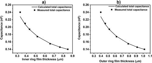
The measured dielectric constant via this method was The literature gives values for various greases varying between 2.88 to 4.76 at atmospheric pressure (Citation41). Pressure increases the dielectric constant (Citation42), so finding a somewhat higher value is plausible.
Determination of the film thickness
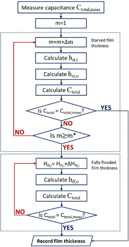
Obtaining grease film thickness during starvation
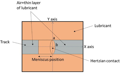
Under starved lubrication conditions, the inlet of the contact will be partially filled up to an inlet meniscus. This is illustrated in . The contribution to the capacitance in the inlet of the contacts will therefore be given by part of the gap filled with oil and part of the gap filled with air and oil layer. The outside capacitance is therefore now a function of the severity of starvation and can only be calculated if the inlet meniscus position is known.
Figure 5. A simplified starved contact condition showing meniscus position on the track.
The equation used to calculate the film thickness hst as a function of the meniscus position, also called ’inlet distance’, is from Dowson and Hamrock (Citation9) and reads
[17]
[17]
where
is the dimensionless inlet meniscus position (x is the meniscus position and b is the half contact width in the x direction);
is the limit of the dimensionless meniscus distance beyond which fully flooded film thickness occurs, obtained from
[18]
[18]
and
is the dimensionless fully flooded film thickness, calculated using EquationEq. [2]
[2]
[2] . The dimensionless meniscus position m will be calculated using an iterative approach. The central film thicknesses for the inner ring is then obtained from EquationEq. [17]
[17]
[17] . The outer ring film thickness is calculated assuming the film thickness ratio for starved and fully flooded conditions are equal. Using this film thickness and meniscus position, Ctotal is calculated. When the contact runs starved, it is assumed that the region outside the running track is still completely filled with oil. The inlet side of the track behind the meniscus is also assumed to be completely filled with oil. The gap between the ball and ring up to the meniscus is filled with air and a layer of oil. The gap between the ball and ring at the outlet across the track is also filled with air and a layer of oil. As mentioned previously, it is assumed that the central lubricant film splits into two equal halves, neglecting the effect of decompression at the outlet. The same dielectric constant of the oil is used for the Hertzian region (pressurized region) and the outside region (depressurized region). The iterative process to find the inlet meniscus position for calculating the starved central film thickness is
Assume m = 1.
Calculate the inner ring starved film thickness
Assume that the ratio of outer and inner ring film thicknesses during starvation is equal to that under fully flooded conditions
Using the dimensionless meniscus position and the film thicknesses, calculate the Ctotal.
Compare the measured and calculated Ctotal.
If the difference is not sufficiently small (e.g., less than 1% difference), check whether the contact is starved or fully flooded by comparing m and When
the contact is fully flooded; otherwise, it is starved. For starved conditions, repeat the process by slightly increasing the meniscus position. For fully flooded conditions, follow the steps described in the next section.
Stop the iteration when the difference is sufficiently small.
Measuring fully flooded grease film thickness
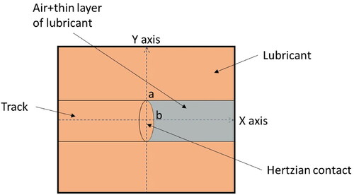
In grease lubrication, the film thickness could be greater than the fully flooded base oil film thickness. This is caused by a higher viscosity of the grease than its base oil, generally observed at low shear rates, hence at very low bearing speeds. In this case, the area around the contact excluding the outlet region is considered to be filled with oil. At the outlet region the space between the ball and ring across the track is considered entirely filled with a layer of oil and air. This is depicted in . Now, the total capacitance is only a function of central film thickness. Here, we vary Hff in EquationEq. [17][17]
[17] until the calculated total capacitance (Ctotal) matches the measured capacitance. The iterative process to find the fully flooded film thickness is
Figure 6. A simplified fully flooded contact condition showing oil around the contact.
Increase the
Use EquationEq. [19]
Use these film thicknesses to calculate the total capacitance Ctotal.
Compare the measured and calculated Ctotal. If the difference is sufficiently small (less than 1% difference), the film thickness is correct. If not, slightly increase
The flow chart of the newly proposed film thickness measurement procedure is shown in .
Figure 7. Flowchart of the newly proposed procedure for determining film thickness in grease lubricated roller bearings.
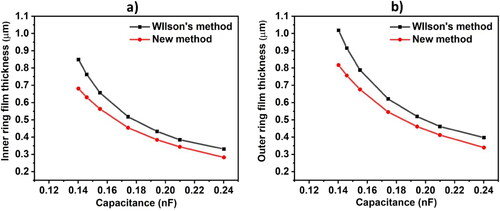
To demonstrate the effect of starvation on the film thickness estimation, a worst case (severe starvation) example calculation is performed. For this, a 6209 deep-groove ball bearing with 513 N axial load and Li/M bled oil was selected. For a set of assumed capacitances, the film thicknesses were calculated using Wilson’s method. Next, using the new method, the film thicknesses were calculated for the same assumed capacitances considering inlet of the contact as severely starved. Here, we considered that the gap between the ball and track in the inlet side is filled with air and a layer of oil while calculating the total capacitance Ctotal. shows a significant increase in the predicted/estimated film thicknesses if the starvation effect is excluded. The percentage deviation of the calculated film thicknesses without considering starvation was up to 20% in this particular case.
Figure 8. Difference in calculated film thickness from Wilson’s method and the new method. Note that this is for an extremely starved condition. (a) Inner ring and (b) outer ring.
Measurement results
Grease film thickness was measured on 6209-2RZ bearing using Li/M grease with 30% of the free volume filling. The bearing was run for 100h to allow completion of the churning phase. Without replacing the grease, all of the following film thickness measurements were made. The speed was varied from 600 to 4,000 rpm. At every speed, film thickness was measured at three different temperatures. A heat gun and a fan were used to control the temperature. At every speed, the temperature and film thickness were allowed to reach a stable value, and average temperature and film thickness were considered for analysis. The measurements were repeated three times to ensure repeatability.
shows that the film thickness is low during the churning phase due to the high temperatures caused by drag and viscous forces leading to high friction and therefore heat generation. After the churning phase, the film thickness becomes steady. This steady phase is the region of interest. The operating conditions are very mild where no significant grease degradation will take place. Moreover, the films are much larger than the surface roughness and the loads are low, causing no bearing damage. Hence, we can use the same bearing for all of our measurements without re-filling the bearing with fresh grease for every measurement.
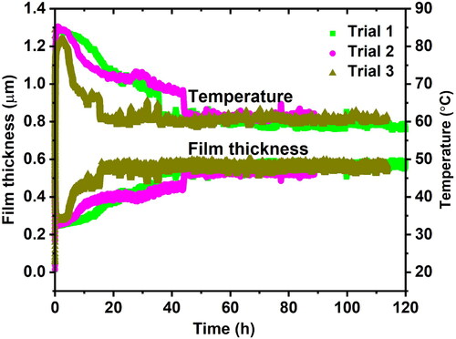
Figure 9. Example of three film thickness and temperature measurements showing that the film thickness is stable after about 60 h. After each measurement the grease was replaced with fresh grease. 6209-2RZ bearing running under self-induced temperature conditions with Li/M grease; load = 513 N, speed = 4,000 rpm.
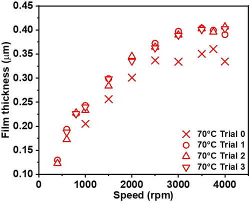
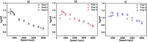
To check whether using the same bearing that has completed the churning phase without freshly re-filling for each subsequent measurement influences the results, a series of measurements was made with freshly filled grease at each speed. After each fresh filling, the bearing ran for 20h, and film thickness was averaged over the last hour. The temperature was maintained at 70C for every measurement. It can be seen from that the film thicknesses of the freshly filled grease (Trial 0) and those without fresh grease (Trials 1, 2, and 3) are very similar, with the freshly filled grease having slightly lower film thickness than those without freshly filled grease. This is because each fresh grease measurement was taken after only 20h of running; it is evident from that at 20h duration, film building may be incomplete.
Figure 10. Comparison of film thickness between fresh grease (Trial 0)—in which each measurement uses fresh grease—to without fresh grease (Trials 1, 2, and3)—in which the same grease is re-used throughout. 6209-2RZ bearing with Li/M grease; load = 513 N.
plots the film thickness versus speed for three temperatures. For each temperature, the film thickness increases up to a certain speed, after which it becomes almost constant. At low speeds, the curves typically follow fully flooded behavior: they increase linearly with the speed on a log-log scale (refer to ). At higher speeds, when the oil supply and/or replenishment is limited to the contact, the slope decreases up to a certain speed, a result of starved lubrication after which it becomes almost zero. This behavior is similar to what was found earlier in single contact measurements, such as those from Guangteng et al. (Citation43) and Cann et al. (Citation20). They also found that the film thickness became constant with increasing speed at some point. However, in these single contact film thickness measurements, this happened under severe starvation. We see here that this phenomenon already occurs when the film thickness is about 30% of the fully flooded values. A possible explanation for the deviation from the single contact measurements could be due to differences in lubricant supply and loss mechanisms to the contacts. Some of these are the differences in grease reservoir adjacent to the tracks, osculation, and the fact that the contacts are elliptical in real ball bearings as opposed to the circular contacts in the single contact setups.
Figure 11. Film thickness versus speed for three different temperatures. 6209-2RZ bearing with Li/M grease; load = 513 N.
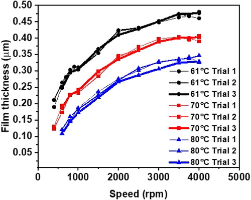
Figure 12. Film thickness versus speed on a log-log scale; 6209-2RZ bearing with Li/M grease; load = 513 N.
The film thickness becoming independent of speed was previously observed by De Laurentis et al. (Citation44), Barz (Citation35), and Cen and Lugt (Citation36). This effect was already predicted by Van Zoelen et al. (Citation10) in their starved EHL model without replenishment. They showed that side flow out from the Hertzian contacts is governed by the time the lubricant spends in the contact (residence time) and the frequency of overrolling. These effects cancel each other out and the net result is that the film thickness is independent of speed. Van Zoelen’s model applies to severely starved conditions and also results in a continuously decreasing film in time, none of which occurs here. Hence, the model cannot be applied to predict the film thickness in a grease-lubricated bearing. In our study, we see a supply of lubricant towards the contacts that is enough to maintain a film. This supply is independent of the space between balls and must therefore be a local replenishment effect (Citation36).
shows the relative film thickness versus speed at the three test temperatures. When
fully flooded conditions persist; when
lubrication is starved. shows the results at 61
C. At speeds lower than 1,000 rpm, relative film thickness is greater than one. After 1,000 rpm, the relative film thickness is less than one, indicating starved lubrication. For 70 and 80
C measurements, a similar behavior is observed but with different transition speeds for each temperature. The transition from fully flooded condition to starved condition takes place at about 1,500 rpm for 70
C and at 2,500 rpm for 80
C. This indicates that the transition from fully flooded condition to starved condition depends on the viscosity of the base oil as well (given that viscosity is a function of temperature).
Figure 13. Relative film thickness versus speed at (a) 61C, (b) 70
C, and (c) 80
C. 6209-2RZ bearing with Li/M grease; load = 513 N.
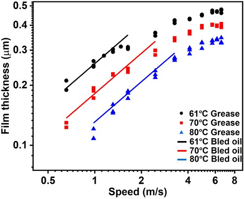
A further analysis of the film thickness was carried out as shown in , which shows that the slope of the film thickness versus speed on log-log plot is 0.67 at lower speeds for all three tested temperatures. From this we can conclude that we can safely use the fully flooded oil film thickness equations to estimate the grease film thickness in bearings using the base oil properties at lower speeds. It should be noted that the real film thickness could be slightly higher than the calculated value. As mentioned above, the film thickness at very low speed is larger than the fully flooded base oil film thickness because of the higher grease viscosity at very low shear rates (and therefore very low speeds in a bearing). The viscosity approaches the base oil viscosity at high shear rates (so higher bearing speeds) (Citation31), so here the film thickness is quite similar to values predicted using the base oil viscosity. In addition to this shear thinning effect, the film thickness could be larger due to thickener particle entrainment in the contact (Citation45). Single contact measurements on ball-on-disc rigs using optical interferometry have shown that lumps of thickener enter the contact at very low speeds (Citation15). This gives a nonuniform film thickness, varying in time. The electrical capacitance is inversely proportional to the thickness of the film, which implies that even small local thin areas of the film have a large impact on the measured film thickness. These “perturbations” will therefore cause much “spread” in the measured film thickness. The combination of film nonuniformity and the non-Newtonian grease rheology leads to very thick films with fluctuating minimum thickness at very low speed, thereby leading to a spread in measured values.
A major difference between our measurements (with pure axial load—hence, all balls are equally loaded, giving equal contact widths) and the measurements that use optical interferometry is that the latter are performed in contacts where one of the surfaces is flat. This means that there is a very large osculation and that grease can flow freely sideways. In bearings the osculation is small and grease is trapped in between seals/shields and the track. The contacts in real bearings are therefore not getting starved as easily as in these “model configurations.” It takes much longer before starvation occurs. We expect therefore that starvation will start to occur at higher speeds and that the replenishment rates will be different, leading to a different film thickness–speed relation. Note that the basic physics is similar; only the ratio of side flow to replenishment is expected to be different between single contact measurements and actual bearing measurements. This leads to similar film thickness versus speed curves, but with different coefficients.
Conclusions
An improved film thickness measurement method, based on an electric capacitance model, including the effect of starvation, has been developed. Under an extremely starved condition, film thickness estimation/prediction could be about 20% higher when starvation effects are excluded. The newly developed method has been used to measure the film thickness in grease-lubricated deep-groove ball bearings as a function of speed at three different temperatures. It is shown that at lower speeds the grease film thickness increases with speed, similar to the base oil film thickness. After a critical speed, the grease film thickness becomes almost independent of speed.
| Nomenclature | ||
| n | = | Number of balls |
| C | = | Capacitance F |
| ϵ0 | = | Permittivity constant [ |
| ϵoil | = | Dielectric constant of oil |
| A | = | Area of the plate |
| h | = | Distance between the parallel plate |
| Ci | = | Ball–inner ring capacitance |
| = | Inner ring outside capacitance for single contact | |
| = | Inner ring Hertz capacitance for single contact [F] | |
| Co | = | Ball-outer ring capacitance |
| = | Inner ring outside capacitance for single contact | |
| = | Outer ring Hertz capacitance for single contact [F] | |
| Cinner | = | Total inner ring capacitance [F] |
| Couter | = | Total outer ring capacitance [F] |
| Ctotal | = | Total calculated bearing capacitance [F] |
| = | Total measured bearing capacitance [F] | |
| Cbackground | = | Background capacitance [F] |
| Cflooded | = | Flooded area capacitance [F] |
| hc | = | Central film thickness [m] |
| = | Ratio of outer ring to inner ring film thickness | |
| hgap | = | Distance between the ball and the surface [m] |
| = | Fully flooded inner ring central film thickness [m] | |
| = | Fully flooded outer ring central film thickness [m] | |
| = | Inner ring grease film thickness [m] | |
| = | Outer ring grease film thickness [m] | |
| hst | = | Starved film thickness [m] |
| Ai | = | Inner ring Hertzian contact area [m2] |
| Ao | = | Outer ring Hertzian contact area [m2] |
| Ccav | = | Capacitance at the outlet [F] |
| ϵair | = | Dielectric constant of air |
| Coutside | = | Outside capacitance of a single contact [F] |
| AHertz | = | Hertzian contact area [m2] |
| Rx | = | Reduced radius in the direction of motion [m] |
| U | = | Dimensionless speed parameter |
| G | = | Dimensionless material parameter |
| W | = | Dimensionless load parameter |
| νcSt | = | Kinematic viscosity [cSt] |
| c | = | Constant in Walther equation [loglogcSt/logK] |
| K | = | Constant in Walther equation [loglogcSt] |
| T | = | temperature [K] |
| η0 | = | Base oil viscosity [Pa.s] |
| us | = | Entrainment velocity |
| = | Reduced elastic modulus [Pa] | |
| F | = | Force [N] |
| Ry | = | Reduced radius in y direction [m] |
| Rx | = | Reduced radius in x direction [m] |
| = | Dimensionless inlet distance at the boundary between fully flooded and starved condition | |
| m | = | Dimensionless meniscus length from the centre of the contact |
| b | = | Half contact width in x direction [m] |
| a | = | Half contact width in y direction [m] |
| = | Dimensionless inner ring fully flooded film thickness | |
| Ro | = | Outer ring radius in the rolling direction [m] |
| Ri | = | Inner ring radius in the rolling direction [m] |
| Rb | = | Ball radius [m] |
| = | Outer ring dynamic viscosity [Pa.s] | |
| = | Inner ring dynamic viscosity [Pa.s] | |
Additional information
Funding
References
- Lugt, P. M. (2012), Grease Lubrication in Rolling Bearings, John Wiley & Sons: Chichester, UK.
- Bonnett, A. H. (1993), “Cause and Analysis of Anti-Friction Bearing Failures in AC Induction Motors,” Conference Record of 1993 Annual Pulp and Paper Industry Technical Conference, pp 36–46, IEEE. doi:10.1109/PAPCON.1993.255813
- Liu, W. (2014), “The Prevalent Motor Bearing Premature Failures Due to the High Frequency Electric Current Passage,” Engineering Failure Analysis, 45, pp 118–127. doi:10.1016/j.engfailanal.2014.06.021
- Lubrecht, A., Venner, C. H., and Colin, F. (2009), “Film Thickness Calculation in Elasto-Hydrodynamic Lubricated Line and Elliptical Contacts: The Dowson, Higginson, Hamrock Contribution,” Proceedings of the Institution of Mechanical Engineers - Part J: Journal of Engineering Tribology, 223(3), pp 511–515. doi:10.1243/13506501JET508
- Hamrock, B. J. and Dowson, D. (1977), “Isothermal Elastohydrodynamic Lubrication of Point Contacts: Part III—Fully Flooded Results,” Journal of Tribology, 99(2), pp 264–275. doi:10.1115/1.3453074
- Nijenbanning, G., Venner, C. H., and Moes, H. (1994), “Film Thickness in Elastohydrodynamically Lubricated Elliptic Contacts,” Wear, 176(2), pp 217–229. doi:10.1016/0043-1648(94)90150-3
- Wedeven, L. D., Evans, D., and Cameron, A. (1971), “Optical Analysis of Ball Bearing Starvation,” Journal of Lubrication Technology, 93(3), pp 349–361. doi:10.1115/1.3451591
- Damiens, B., Venner, C. H., Cann, P., and Lubrecht, A. (2004), “Starved Lubrication of Elliptical EHD Contacts,” Journal of Tribology, 126(1), pp 105–111. doi:10.1115/1.1631020
- Hamrock, B. J. and Dowson, D. (1977), “Isothermal Elastohydrodynamic Lubrication of Point Contacts: Part IV—Starvation Results,” Journal of Tribology, 99(1), pp 15–22. doi:10.1115/1.3452973
- Van Zoelen, M., Venner, C. H., and Lugt, P. M. (2009), “Prediction of Film Thickness Decay in Starved Elasto-Hydrodynamically Lubricated Contacts Using a Thin Layer Flow Model,” Proceedings of the Institution of Mechanical Engineers - Part J: Journal of Engineering Tribology, 223(3), pp 541–552. doi:10.1243/13506501JET524
- Poon, S.-Y. (1972), “An Experimental Study of Grease in Elastohydrodynamic Lubrication,” Journal of Lubrication Technology, 94(1), pp 27–34. doi:10.1115/1.3451631
- Wilson, A. (1979), “The Relative Thickness of Grease and Oil Films in Rolling Bearings,” Proceedings of the Institution of Mechanical Engineers, 193(1), pp 185–192. doi:10.1243/PIME_PROC_1979_193_019_02
- Dyson, A. and Wilson, A. (1969), “Film Thicknesses in Elastohydrodynamic Lubrication of Rollers by Greases,” Proceedings of the Institution of Mechanical Engineers, Conference Proceedings, Vol. 184, pp 1–11. SAGE: London. doi:10.1243/PIME_CONF_1969_184_137_02
- Jonkisz, W. and Krzeminski-Freda, H. (1979), “Pressure Distribution and Shape of an Elastohydro-Dynamic Grease Film,” Wear, 55(1), pp 81–89. doi:10.1016/0043-1648(79)90181-9
- Åström, H., Isaksson, O., and Höglund, E. (1991), “Video Recordings of an EHD Point Contact Lubricated with Grease,” Tribology International, 24(3), pp 179–184. doi:10.1016/0301-679X(91)90024-4
- Cann, P. and Spikes, H. (1992), “Fourier-Transform Infrared Study of the Behavior of Grease in Lubricated Contacts,” Lubrication Engineering, 48, pp 335–343.
- Booser, E. and Wilcock, D. (1953), “Minimum Oil Requirements of Ball Bearings,” Lubrication Engineering, 9(3), pp 140–143.
- Baker, A. (1958), “Grease Bleeding—A Factor in Ball Bearing Performance,” NLGI Spokesman, 22(9), pp 271–277.
- Wikström, V. and Jacobson, B. (1997), “Loss of Lubricant from Oil-Lubricated Near-Starved Spherical Roller Bearings,” Proceedings of the Institution of Mechanical Engineers - Part J: Journal of Engineering Tribology, 211(1), pp 51–66. doi:10.1243/1350650971542318
- Cann, P., Damiens, B., and Lubrecht, A. (2004), “The Transition between Fully Flooded and Starved Regimes in EHL,” Tribology International, 37(10), pp 859–864. doi:10.1016/j.triboint.2004.05.005
- Cann, P., Chevalier, F., and Lubrecht, A. (1997), “Track Depletion and Replenishment in a Grease Lubricated Point Contact: A Quantitative Analysis,” Tribology Series, Vol. 32, pp 405–413. Elsevier. doi:10.1016/S0167-8922(08)70469-3
- Gershuni, L., Larson, M. G., and Lugt, P. M. (2008), “Lubricant Replenishment in Rolling Bearing Contacts,” Tribology Transactions, 51(5), pp 643–651. doi:10.1080/10402000802192529
- Jacod, B., Pubilier, F., Cann, P., and Lubrecht, A. (1999), “An Analysis of Track Replenishment Mechanisms in the Starved Regime,” Tribology Series, Vol. 36, pp 483–492. Elsevier. doi:10.1016/S0167-8922(99)80069-8
- Mérieux, J., Hurley, S., Lubrecht, A., and Cann, P. (2000), “Shear-Degradation of Grease and Base Oil Availability in Starved EHL Lubrication,” Tribology series, Vol. 38, pp 581–588. Elsevier. doi:10.1016/S0167-8922(00)80162-5
- Chiu, Y. (1974), “An Analysis and Prediction of Lubricant Film Starvation in Rolling Contact Systems,” ASLE Transactions, 17(1), pp 22–35. doi:10.1080/05698197408981435
- Guangteng, G. and Spikes, H. (1996), “The Role of Surface Tension and Disjoining Pressure in Starved and Parched Lubrication,” Proceedings of the Institution of Mechanical Engineers - Part J: Journal of Engineering Tribology, 210(2), pp 113–124. doi:10.1243/PIME_PROC_1996_210_487_02
- Nogi, T. (2015), “An Analysis of Starved EHL Point Contacts with Reflow,” Tribology Online, 10(1), pp 64–75. doi:10.2474/trol.10.64
- Nogi, T. (2015), “Film Thickness and Rolling Resistance in Starved Elastohydrodynamic Lubrication of Point Contacts with Reflow,” Journal of Tribology, 137(4), p 041502. doi:10.1115/1.4030203
- Fischer, D., von Goeldel, S., Jacobs, G., and Stratmann, A. (2021), “Numerical Investigation of Effects on Replenishment in Rolling Point Contacts Using CFD Simulations,” Tribology International, 157, p 106858. doi:10.1016/j.triboint.2021.106858
- Van Zoelen, M. T., Venner, C. H., and Lugt, P. M. (2008), “Free Surface Thin Layer Flow on Bearing Raceways,” Journal of Tribology, 130(2), pp 021802–1–021802-10. doi:10.1115/1.2805433
- Morales-Espejel, G. E., Lugt, P. M., Pasaribu, H., and Cen, H. (2014), “Film Thickness in Grease Lubricated Slow Rotating Rolling Bearings,” Tribology International, 74, pp 7–19. doi:10.1016/j.triboint.2014.01.023
- Cen, H. and Lugt, P. M. (2020), “Replenishment of the EHL Contacts in a Grease Lubricated Ball Bearing,” Tribology International, 146, p 106064. doi:10.1016/j.triboint.2019.106064
- Lewicki, W. (1955), Some Physical Aspects of Lubrication in Rolling Bearings and Gears, PhD Thesis, University of London (Birkbeck College).
- Crook, A. (1961), “The Lubrication of Rollers II. Film Thickness with Relation to Viscosity and Speed,” Philosophical Transactions of the Royal Society of London. Series A, Mathematical and Physical Sciences, 254(1040), pp 223–236.
- Barz, M. (1996), Die Schmierfilmbildung in Fettgeschmierten Schnellaufenden Spindellagern, PhD Thesis, Verlag Nicht Ermittelbar.
- Cen, H. and Lugt, P. M. (2019), “Film Thickness in a Grease Lubricated Ball Bearing,” Tribology International, 134, pp 26–35. doi:10.1016/j.triboint.2019.01.032
- Jablonka, K., Glovnea, R., and Bongaerts, J. (2012), “Evaluation of EHD Films by Electrical Capacitance,” Journal of Physics D: Applied Physics, 45(38), p 385301. doi:10.1088/0022-3727/45/38/385301
- Jablonka, K., Glovnea, R., and Bongaerts, J. (2018), “Quantitative Measurements of Film Thickness in a Radially Loaded Deep-Groove Ball Bearing,” Tribology International, 119, pp 239–249. doi:10.1016/j.triboint.2017.11.001
- Jablonka, K., Glovnea, R., Bongaerts, J., and Morales-Espejel, G. (2013), “The Effect of the Polarity of the Lubricant upon Capacitance Measurements of EHD Contacts,” Tribology International, 61, pp 95–101. doi:10.1016/j.triboint.2012.11.016
- Heemskerk, R., Vermeiren, K., and Dolfsma, H. (1982), “Measurement of Lubrication Condition in Rolling Element Bearings,” ASLE Transactions, 25(4), pp 519–527. doi:10.1080/05698198208983121
- Wittek, E., Kriese, M., Tischmacher, H., Gattermann, S., Ponick, B., and Poll, G. (2010), “Capacitances and Lubricant Film Thicknesses of Motor Bearings under Different Operating Conditions,” The XIX International Conference on Electrical Machines-ICEM 2010, pp 1–6. IEEE. doi:10.1109/ICELMACH.2010.5608142
- Mopsik, F. I. (1967), “Dielectric Constant of n-Hexane as a Function of Temperature, Pressure, and Density,” Journal of Research of the National Bureau of Standards. Section A, Physics and Chemistry, 71(4), p 287.
- Guangteng, G., Cann, P., and Spikes, H. (1992), “A Study of Parched Lubrication,” Wear, 153(1), pp 91–105. doi:10.1016/0043-1648(92)90263-8
- De Laurentis, N., Liang, H., Lugt, P. M., and Kaderic, A. (2019), “Investigation into the Influence of Bearing Operational Conditions on Grease Film Thickness Using a Model Rolling Bearing Rig,” Extended Abstract International Tribology Conference,Sendai, Japan.
- Cyriac, F., Lugt, P. M., Bosman, R., Padberg, C. J., and Venner, C. H. (2016), “Effect of Thickener Particle Geometry and Concentration on the Grease EHL Film Thickness at Medium Speeds,” Tribology Letters, 61(2), pp 1–13
- Jablonka, K., Glovnea, R., Bongaerts, J., and Morales-Espejel, G. (2012), “Comparative Measurements of EHD Film Thickness in Ball-on-Flat Rig and Rolling Element Bearing,” STLE 67th Annual Meeting, pp 6–10, St. Louis, USA.