
Abstract
Due to the limited cooling capacity of air, large-scale proton exchange membrane (PEM) fuel cell stacks are generally cooled by liquid cooling where liquid water is circulated through the flow channels of cooling plates. Effective cooling is essential for the stability, durability, and performance of PEM fuel cells. In this study, cooling plates with conventional straight channel and novel non-uniform flow channel designs are investigated and analyzed by using a three-dimensional model. The simulated results are presented in terms of pressure drop, average temperature, maximum temperature, temperature difference between the maximum temperature and minimum temperature, and the temperature uniformity index. In addition, the effects of heat flux and inlet Reynolds number on the cooling performance are studied. It is concluded that the cooling performance is significantly improved as the novel flow channel designs are applied.
1. Introduction
Proton exchange membrane (PEM) fuel cells are electrochemical conversion devices where the electrical energy is produced directly through the hydrogen oxidation reaction and oxygen reduction reaction at the anode and cathode catalyst layers, respectively [Citation1]. Due to the advantages of high power density, rapid startup, and low operating temperature, PEM fuel cells can be utilized for varying applications based on the desired requirements [Citation2–4]. When humidified hydrogen and oxygen are supplied to fuel cell stacks, the electricity, water and heat are generated simultaneously.
Numerical simulations have been carried out to improve the understanding of PEM fuel cells [Citation5–10]. Water and thermal managements are two important issues that have significant impacts on the performance, stability, and durability of PEM fuel cells [Citation11–14]. During the operating process, the membrane must be well hydrated to reduce the proton transport resistance associated with local temperature and water content. However, excessive water can block the transport passages in the porous regions and consequently lead to water flooding problem. In addition, a considerable amount of heat is produced continuously within PEM fuel cells, and it is the same order of magnitude as the generated electrical power. The produced heat must be effectively dissipated to reduce the maximum temperature and avoid overheating of fuel cells by means of appropriate thermal management. A higher temperature increases the electrochemical reaction rate and may also cause membrane dehydration and performance degradation, whereas a lower temperature may lead to water flooding. Therefore, it is necessary to carefully control the temperature and maintain a small temperature variation in a PEM fuel cell. In a PEM fuel cell stack system, a cooling system is needed to meet the requirement of heat removal from fuel cells. There are different types of cooling methods used for PEM fuel cell stacks, such as edge cooling, liquid cooling and phase change cooling. The advantages and disadvantages of the cooling methods were comprehensively demonstrated by Zhang and Kandlikar [Citation15].
Due to the limited cooling capacity of air, large-scale PEM fuel cell stacks are generally cooled by liquid cooling where liquid water is circulated through the flow channels of cooling plates [Citation16–28]. The performance of cooling plates with various parallel and serpentine flow fields were numerically investigated by Chen et al. [Citation19]. It was concluded that the cooling effect of the serpentine channel design is better than that of parallel flow design, while the pressure drop of parallel flow design is lower than that of serpentine channel design. Yu et al. [Citation20] reported the performance of cooling plates with several multi-pass serpentine flow fields employed as coolant channels. The cooling effect which is evaluated by the maximum temperature and temperature uniformity of the multi-pass serpentine flow fields, was significantly improved in comparison with the conventional serpentine flow field. In addition, the effects of flow velocity and heat flux on the cooling effect were examined and compared. Similarly, a numerical study on the performance of cooling plates with parallel, serpentine and multi-pass serpentine flow fields was conducted by Baek et al. [Citation21]. The results revealed that the temperature uniformity of multi-pass serpentine flow field design can be significantly improved when the coolant flow rate of parallel paths can be properly distributed. The heat transfer performance of eight cooling channel designs including parallel, serpentine, wavy, oblique fin, and coiled-based channels were analyzed by Kurnia et al. [Citation22]. The advantages and disadvantages of various designs were comprehensively discussed. It was found that a higher and more uniform heat transfer rate was provided by the coiled-based channel design but a higher pressure drop was also accompanied. The divided/distributed serpentine and spiral flow channel designs proposed by Ravishankar and Prakash [Citation23] were used for the cooling of PEM fuel cell stacks with air as the coolant. The results indicated that the thermal performance in terms of temperature uniformity was improved by using the novel designs at all Reynolds numbers. The performance of cooling plates with parallel, serpentine, and metal foam porous media flow field designs were investigated and compared by Afshari et al. [Citation24]. The maximum temperature and average temperature of the cooling plate with metal foam flow field design were much lower than those of the remaining flow designs. In addition, the performance of the metal foam flow field design with varying physical properties was systematically analyzed. The thermal performance of chaotic geometries proposed by Lasbet et al. [Citation25–27] was numerically and experimentally investigated. The results revealed that the convective heat transfer is substantially improved when chaotic geometries are employed. Recently, a novel zigzag-shaped flow field was applied to cooling plates [Citation28]. The fluid flow and heat transfer characteristics of the novel design were studied and compared to the conventional straight channel flow field design.
Water is supplied and circulated in the channels of cooling plates to control the temperature inside PEM fuel cells. A uniform temperature distribution and a small temperature variation are desired to improve the stability, durability, and performance of PEM fuel cells. Effective cooling is very important for the performance improvement of PEM fuel cells, so various cooling channel designs are proposed and studied by researchers. The cooling performance of water gradually deceases along the channels, and the temperature variation of PEM fuel cells between inlet part and outlet part consequently increases. Therefore, it is essential to improve the thermal performance at the downstream of the cooling channels. In this study, a novel cooling channel design with non-uniform cross-sectional area along the flow direction is proposed. Four cooling channels including one conventional straight channel and three novel channels are investigated and estimated by using a computational fluid dynamics (CFD) technique. The fully coupled fluid flow and heat transfer transport processes are solved by using the finite volume method. The thermal performance of four cooling channels are exhibited and compared in terms of maximum temperature, average temperature, temperature difference, and temperature uniformity index. In addition, the effects of heat flux and inlet Reynolds number on thermal performance are examined.
2. Model description
In general, several fuel cell units are serially connected to form a fuel cell stack and generate the desired level of output power, as shown in . The performance improvement of PEM fuel cells can be obtained by increasing the operating temperature due to an increase in the electrochemical kinetic rates at the catalyst layers. To protect the fuel cell from overheating, a coolant flows through the channels of the cooling plate and removes the generated heat. The cooling plates in a fuel cell stack are arranged in a repetitive order and employed to cool several fuel cell units. The heat fluxes on the top and bottom surfaces of the cooling plate are from the heat produced by the electrochemical reactions. As shown in , H, L, and W represent the height, length, and width of the cooling channel, respectively. Due to symmetry of the geometry, only one half cooling channel is modeled as the computational domain, as shown in . The current study focuses on the thermal performance of the cooling plates in PEM fuel cell stacks. Non-uniform flow channels are proposed and designed to improve the cooling performance. Four cases, i.e., Case A, Case B, Case C, and Case D are considered in this study. For Case A, the channel height and width are kept constant. For Case B, the channel height is kept constant, whereas the channel width is gradually increased along the flow direction. For Case C, the channel width is kept constant, whereas the channel height is gradually decreased along the flow direction. Finally for Case D, the channel height is gradually decreased, whereas the channel width is gradually increased along the flow direction. Case A is the conventional straight channel, which has the constant cross-sectional area. The cross-sectional area of the channel outlet of Case B is increased, whereas the cross-sectional area of the channel outlet of both Case C and Case D is decreased. The detailed parameters of the geometry configurations are summarized in and .
Figure 1. Schematic of a PEMFC stack with cooling plates.
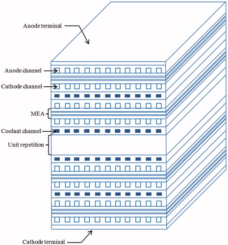
Figure 2. Schematic of the cooling plate of PEM fuel cells.
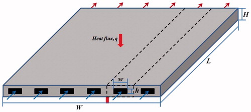
Figure 3. Schematic of the computational domain in this study.
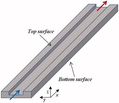
Table 1. Geometric parameters of the cooling plate and operating condition [Citation21,Citation24].
Table 2. Geometric parameters of Case A, Case B, Case C, and Case D.
2.1. Governing equations
The mass, momentum, and energy conservation equations for the fluid flow and heat transfer in the computational domain are presented as follows:
2.1.1. Mass conservation equation
where ρ and are the fluid density and velocity, respectively.
2.1.2. Momentum conservation equation
where P and μ are the pressure and dynamic viscosity, respectively.
2.1.3. Energy conservation equation
where Cp is the specific heat, kf is the thermal conductivity of the fluid, and T is the temperature. For the solid region, the energy equation is described by(4)
In this study, the cooling plate is made of graphite, and the working fluid is water. The thermo-physical properties of water are determined by polynomial functions of temperature [Citation22]. The density, dynamic viscosity, and thermal conductivity of the water are given by(5)
(6)
(7)
The thermo-physical properties of graphite and the specific heat of water are summarized in .
Table 3. Thermo-physical properties of the solid and fluid regions [20,21].
Reynolds number is defined as(8) where u is the average inlet velocity, Dh is the hydraulic diameter of the channel, which is equal to 1.33 mm.
The temperature uniformity index, which is used to evaluate the uniformity of temperature distribution across the surface area [Citation19], is defined as(9) where A is the surface area and Tavg is the average temperature of the entire surface area.
(10)
2.2. Numerical implementation and boundary conditions
The governing equations are solved by using the commercial software ANSYS FLUENT. The coupling of pressure and velocity fields is handled by the SIMPLE algorithm. To ensure accuracy, the second-order upwind scheme is adopted for the momentum and energy equations spatial discretization, while the standard scheme is applied for pressure discretization. The temperature dependent properties of water are implemented by using the user-defined functions (UDF) written in C language.
At the inlet of the channel, the inlet temperature and the mass flow rate are specified. The mass flow rate is calculated based on the inlet Reynolds number which is equal to 250. At the outlet of the channel, pressure-outlet boundary condition is adopted. The bottom surface of the cooling plate is prescribed as a constant heat flux surface, whereas the top surface is defined as a symmetry boundary condition. The interface between fluid and solid regions is coupled for temperature calculation. The computations are considered to be converged when the residuals of all governing equations become less than 1 × 10⁻⁶.
2.3. Mesh independence
To ensure that the numerical results are independent of the mesh number, a systematical mesh independence test is carried out. The structured mesh is generated by using the software ICEM CFD. Five different mesh systems are generated for Case A, which are Mesh I, Mesh II, Mesh III, Mesh IV, and Mesh V, respectively. The corresponding results of pressure drop, maximum temperature, and average temperature are summarized in . It can be seen that the difference of the results between Mesh IV and Mesh V is very small. Therefore, the number of Mesh IV is used for the numerical study.
Table 4. Temperature and pressure drop for different mesh systems.
3. Results and discussions
In this section, the heat transfer and fluid flow characteristics of four cases are presented and analyzed. Then the effects of heat flux and inlet Reynolds number on cooling performance are also investigated.
3.1. Model validation
Prior to numerical calculations, a numerical simulation is carried out and compared to the available data in the open literature. The simulated results and the results reported by Baek et al. [Citation21] are plotted in , showing good agreement between them. The same geometry and operating conditions (heat flux, inlet temperature, and mass flow rate) are used to verify the mathematical model utilized in this study.
Figure 4. Comparison of the simulated results with the results reported by Baek et al. [Citation21].
![Figure 4. Comparison of the simulated results with the results reported by Baek et al. [Citation21].](/cms/asset/89915cf7-ec04-42a4-9fe3-c3512ad8ebf3/unht_a_1486642_f0004_c.jpg)
3.2. Heat transfer characteristics
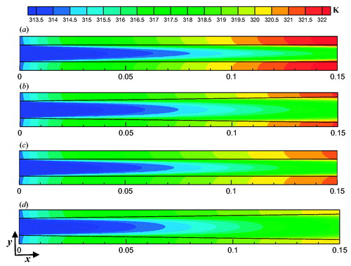
The bottom surface temperature distributions of four cases are shown in . It is clearly observed that the temperature gradually increases along the flow direction due to the degradation of the water cooling capacity. The minimum temperature value is almost the same for all cases, whereas the maximum temperature value differs from Case A to Case D. As seen in , the values of maximum temperature, average temperature, temperature difference, and temperature uniformity index are considerably decreased when the novel non-uniform flow channel designs are applied in the cooling plates. When the minimum temperature is kept constant, a decrease in maximum temperature can lead to a more uniform temperature distribution. The temperature difference is the difference between the maximum surface temperature and minimum surface temperature. The values of the temperature difference for four cases are 8.283 K, 7.426 K, 7.019 K, and 6.300 K, respectively. The values of the temperature difference of Case B, Case C, and Case D are decreased by 10.35%, 15.26% and 23.94% compared to Case A. In EquationEq. 9(9) , the value of the temperature uniformity index reaches zero value, when the local temperature is equal to the average temperature. This indicates that the temperature across the entire surface is perfectly uniform. The values of the temperature uniformity index for four cases are 1.765 K, 1.527 K, 1.438 K, and 1.224 K, respectively. The values of the temperature difference of Case B, Case C, and Case D are decreased by 13.48%, 18.53%, and 30.65% compared to Case A.
Figure 5. Bottom surface temperature distributions of the cooling plates: (a) Case A; (b) Case B; (c) Case C; (d) Case D.
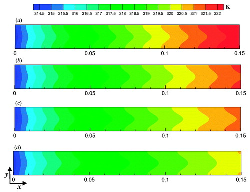
Table 5. Numerical results of the cooling plate with different channel designs.
displays the temperature distributions at the top surface (central plane of the channel) of four cases. The minimum temperature appears at the inlet part of the fluid region, whereas the maximum temperature exists at the outlet part of the solid region. The significant difference observed in the distributions is the different maximum temperature values. This indicates that the cooling performance is significantly improved at the downstream of the cooling plates.
Figure 6. Central plane temperature distributions of the cooling plates: (a) Case A; (b) Case B; (c) Case C; (d) Case D.
3.3. Fluid flow characteristics
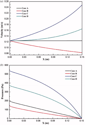
Due to the non-uniform cross-sectional area of the cooling channels, the velocity and pressure are significantly altered in comparison with the conventional straight channel. shows the average velocity of four cases along the flow direction. The average velocity of Case A is slightly increased due to the decrease in density caused by the increased temperature. Because the cross-sectional area of the cooling channel is increased, the average velocity of Case B is consequently decreased. The average velocities of the remaining cases (Case C and Case D) are rapidly increased along the flow direction, especially for Case C. An increase in velocity can enhance the convective heat transfer, but also increase the pressure drop penalty. The local pressure of four cases along the flow direction is presented in . As expected, the pressure drop of Case B is lower than that of Case A, whereas the pressure drops of Case C and Case D are significantly greater than that of Case A. The values of pressure drop of four cases are 200.968 Pa, 145.903 Pa, 541.304 Pa, and 375.611 Pa, respectively.
Figure 7. (a) Average velocity of four cases along the channel; (b) local pressure of four cases along the channel.
3.4. Effect of heat flux
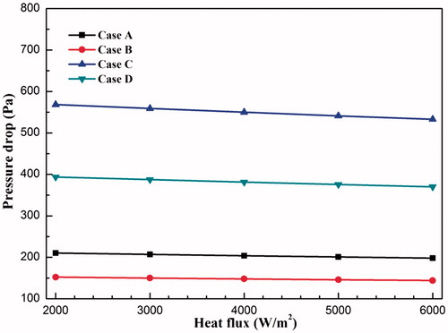
The effect of heat flux on heat transfer and fluid flow characteristics of four cases are investigated and compared, as shown in and . It is clearly seen that the maximum temperature of four cases is linearly increased with the heat flux ranging from 2,000 W/m2 to 6,000 W/m2, as well as the average temperature, temperature difference, and temperature uniformity index. The sequence of cooling performance of four cases is not changed with the variation of heat flux. In addition, the difference of the corresponding variables between each two cases is significantly increased when the heat flux is increased. The pressure drop of four cases under different heat fluxes is presented in . The pressure drop is slightly decreased with increasing heat flux, because the dynamic viscosity of water is decreased when the temperature becomes higher.
Figure 8. Effect of heat flux on the heat transfer characteristics: (a) maximum temperature; (b) average temperature; (c) temperature difference; (d) temperature uniformity index.
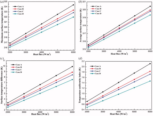
Figure 9. Effect of heat flux on pressure drop of four cases.
3.5. Effect of inlet Reynolds number
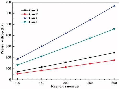
As shown in and , the effect of inlet Reynolds number on heat transfer and fluid flow characteristics of four cases are also investigated and compared. It is clearly observed that the maximum temperature of four cases is substantially decreased with the inlet Reynolds number ranging from 100 to 300, as well as the average temperature, temperature difference, and temperature uniformity index. In addition, the difference of the corresponding variables between each two cases is almost the same at different inlet Reynolds numbers. depicts the variation of pressure drop for different inlet Reynolds numbers. The pressure drop of four cases is linearly increased with increasing inlet Reynolds numbers, and the increment of Case C is the largest, followed by Case D, Case A, and Case B.
Figure 10. Effect of inlet Reynolds number on the heat transfer characteristics: (a) maximum temperature; (b) average temperature; (c) temperature difference; (d) temperature uniformity index.
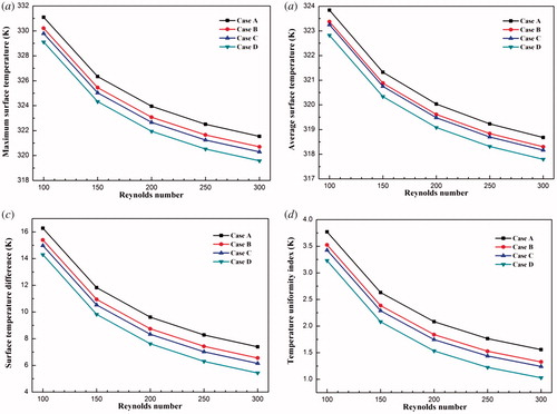
Figure 11. Effect of inlet Reynolds number on pressure drop of four cases.
4. Conclusions
In this study, the thermal performance of a conventional flow channel and novel flow channels with non-uniform cross-sectional area is numerically investigated by using a three dimensional model involving coupled fluid flow and heat transfer processes. Based on the numerical results, the following conclusions are drawn:
The cooling plate bottom surface temperature is gradually increased along the channel because the generated heat is absorbed by the water. This indicates the cooling performance degradation of water. The concept of non-uniform cross-sectional area along the channel is applied in the channels of the cooling plate to improve the cooling performance at the downstream region of the channels. The results show that the maximum temperature and temperature difference are significantly decreased. The pressure drop between the inlet and outlet of the channel is also increased, except for Case B, with increasing cross-sectional area. It is suggested that the non-uniform flow channel designs can be used for the cooling plates of PEM fuel cells to improve the cooling performance.
| Nomenclature | ||
| A | = | area, m2 |
| Cp | = | specific heat, J kg−1 K−1 |
| Dh | = | hydraulic diameter, m |
| h | = | height of the channel, m |
| H | = | height of the plate, m |
| k | = | thermal conductivity, W m−1 K−1 |
| L | = | length of the plate, m |
| P | = | pressure, Pa |
| Re | = | Reynolds number |
| T | = | temperature, K |
| = | velocity vector, m/s | |
| U | = | uniformity |
| w | = | width of the channel, m |
| W | = | width of the plate, m |
| Greek symbols | ||
| μ | = | dynamic viscosity, Pa s |
| ρ | = | density, kg m−3 |
| Subscripts | ||
| avg | = | average |
| f | = | fluid region |
| i | = | inlet of the channel |
| max | = | maximum |
| min | = | minimum |
| o | = | outlet of the channel |
| s | = | solid region |
| Abbreviations | ||
| CFD | = | computational fluid dynamics |
| PEM | = | proton exchange membrane |
| UDF | = | user-defined functions |
Acknowledgments
The work was carried out at the Department of Energy Sciences, Lund University.
Additional information
Funding
References
- F. Barbir, PEM Fuel Cells: Theory and Practice. Cambridge: Elsevier, Academic Press, 2013.
- S. J. C. Cleghorn et al., “PEM fuel cells for transportation and stationary power generation applications,” Int. J. Hydrogen Energy, vol. 22, no. 12, pp. 1137–1144, 1997. DOI: 10.1016/S0360-3199(97)00016-5.
- R. K. Ahluwalia and X. Wang, “Fuel cell systems for transportation: status and trends,” J. Power Sources, vol. 177, no. 1, pp. 167–176, 2008. DOI: 10.1016/j.jpowsour.2007.10.026.
- Y. Wang, K. S. Chen, J. Mishler, S. C. Cho, and X. C. Adroher, “A review of polymer electrolyte membrane fuel cells: technology, applications, and needs on fundamental research,” Appl. Energy, vol. 88, no. 4, pp. 981–1007, 2011. DOI: 10.1016/j.apenergy.2010.09.030.
- L. Chen, Y. L. He, and W. Q. Tao, “The temperature effect on the diffusion processes of water and proton in the proton exchange membrane using molecular dynamics simulations,” Numer. Heat Transfer A, vol. 65, no. 3, pp. 216–228, 2014. DOI: 10.1080/10407782.2013.784677.
- S. A. Li, J. L. Yuan, G. N. Xie, and B. Sunden, “Numerical investigation of transport phenomena in high temperature proton exchange membrane fuel cells with different flow field designs,” Numer. Heat Transfer A, vol. 72, no. 11, pp. 807–820, 2017. DOI: 10.1080/10407782.2017.1412221.
- C. L. Han, and Z. Q. Chen, “Numerical simulation for the effect of vaporization intensity in membrane on the performance of PEM fuel cell,” Numer. Heat Transfer A, vol. 73, no. 3, pp. 177–194, 2018. DOI: 10.1080/10407782.2017.1421370.
- S. A. Li, J. L. Yuan, M. Andersson, G. N. Xie, and B. Sunden, “Wavy surface cathode gas flow channel effects on transport processes in a proton exchange membrane fuel cell,” ASME J. Electrochem. En. Conv. Stor, vol. 14, no. 3, pp. 031007, 2017. DOI: 10.1115/1.4036810.
- S. A. Li, J. L. Yuan, M. Andersson, G. N. Xie, and B. Sunden, “Influence of anisotropic gas diffusion layers on transport phenomena in a proton exchange membrane fuel cell,” Int. J. Energy Res, vol. 41, no. 14, pp. 2034–2050, 2017. DOI: 10.1002/er.3763.
- S. A. Li, J. L. Yuan, G. N. Xie, and B. Sunden, “Effects of agglomerate model parameters on transport characterization and performance of PEM fuel cells,” Int. J. Hydrogen Energy, vol. 43, no. 17, pp. 8451–8463, 2018. DOI: 10.1016/j.ijhydene.2018.03.106.
- Y. Zong, B. Zhou, and A. Sobiesiak, “Water and thermal management in a single PEM fuel cell with non-uniform stack temperature,” J. Power Sources, vol. 161, no. 1, pp. 143–159, 2006. DOI: 10.1016/j.jpowsour.2006.02.107.
- S. G. Kandlikar, and Z. Lu, “Thermal management issues in a PEMFC stack – a brief review of current status,” Appl. Therm. Eng, vol. 29, no. 7, pp. 1276–1280, 2009. DOI: 10.1016/j.applthermaleng.2008.05.009.
- J. E. Dawes, N. S. Hanspal, O. A. Family, and A. Turan, “Three-dimensional CFD modeling of PEM fuel cells: an investigation into the effects of water flooding,” Chem. Eng. Sci, vol. 64, no. 12, pp. 2781–2794, 2009. DOI: 10.1016/j.ces.2009.01.060.
- F. Nandjou, J. P. Crouvezier, M. Chandesris, J. F. Blachot, C. Bonnaud, and Y. Bultel, “Impact of heat and water management on proton exchange membrane fuel cells degradation in automotive application,” J. Power Sources, vol. 326, pp. 182–192, 2016. DOI: 10.1016/j.jpowsour.2016.07.004.
- G. Zhang, and S. G. Kandlikar, “A critical review of cooling techniques in proton exchange membrane fuel cell stacks,” Int. J. Hydrogen Energy, vol. 37, no. 3, pp. 2412–2429, 2012. DOI: 10.1016/j.ijhydene.2011.11.010.
- M. Matian, A. Marquis, and N. Brandon, “Model based design and test of cooling plates for an air-cooled polymer electrolyte fuel cell stack,” Int. J. Hydrogen Energy, vol. 36, no. 10, pp. 6051–6066, 2011. DOI: 10.1016/j.ijhydene.2011.01.026.
- A. P. Sasmito, K. W. Lum, E. Birgersson, and A. S. Mujumdar, “Computational study of forced air-convection in open cathode polymer electrolyte fuel cell stacks,” J. Power Sources, vol. 195, no. 17, pp. 5550–5563, 2010. DOI: 10.1016/j.jpowsour.2010.02.083.
- S. Shahsavari, A. Desouza, M. Bahrami, and E. Kjeang, “Thermal analysis of air-cooled PEM fuel cells,” Int. J. Hydrogen Energy, vol. 37, no. 23, pp. 18261–18271, 2012. DOI: 10.1016/j.ijhydene.2012.09.075.
- F. C. Chen, Z. Gao, R. O. Loutfy, and M. Hecht, “Analysis of optimal heat transfer in a PEM fuel cell cooling plate,” Fuel Cells, vol. 3, no. 4, pp. 181–188, 2003. DOI: 10.1002/fuce.200330112.
- S. H. Yu, S. Sohn, J. H. Nam, and C. J. Kim, “Numerical study to examine the performance of multi-pass serpentine flow-fields for cooling plates in polymer electrolyte membrane fuel cells,” J. Power Sources, vol. 194, no. 2, pp. 697–703, 2009. DOI: j.jpowsour.2009.06.025.
- S. M. Baek, S. H. Yu, J. H. Nam, and C. J. Kim, “A numerical study on uniform cooling of large-scale PEMFCs with different flow field designs,” Appl. Therm. Eng, vol. 31, no. 8-9, pp. 1427–1434, 2011. DOI: 10.1016/j.applthermaleng.2011.01.009.
- J. C. Kurnia, A. P. Sasmito, and A. S. Mujumdar, “Numerical investigation of laminar heat transfer performance of various cooling channel designs,” Appl. Therm. Eng, vol. 31, no. 6-7, pp. 1293–1304, 2011. DOI: 10.1016/j.applthermaleng.2010.12.036.
- S. Ravishankar, and K. A. Prakash, “Numerical studies on thermal performance of novel cooling plate designs in polymer electrolyte membrane fuel cell stacks,” Appl. Therm. Eng, vol. 66, no. 1-2, pp. 239–251, 2014. DOI: 10.1016/j.applthermaleng.2014.01.068.
- E. Afshari, M. Ziaei-Rad, and Z. Shariati, “A study on using metal foam as coolant fluid distributor in the polymer electrolyte membrane fuel cell,” Int. J. Hydrogen Energy, vol. 41, no. 3, pp. 1902–1912, 2016. DOI: 10.1016/j.ijhydene.2015.10.122.
- Y. Lasbet, B. Auvity, C. Castelain, and H. Peerhossaini, “Thermal and hydrodynamic performances of chaotic mini-channel: application to the fuel cell cooling,” J. Heat Transf. Eng, vol. 28, no. 8–9, pp. 795–803, 2007. DOI: 10.1080/01457630701328908.
- Y. Lasbet, B. Auvity, C. Castelain, and H. Peerhossaini, “A chaotic heat exchanger for PEMFC cooling applications,” J. Power Sources, vol. 156, no. 1, pp. 114–118, 2006. DOI: 10.1016/j.jpowsour.2005.08.030.
- C. Castelain, Y. Lasbet, B. Auvity, and H. Peerhossaini, “Experimental study of the thermal performance of chaotic geometries for their use in PEM fuel cells,” Int. J. Therm. Sci, vol. 101, pp. 181–192, 2016. DOI: 10.1016/j.ijthermalsci.2015.10.033.
- E. Afshari, M. Ziaei-Rad, and M. M. Dehkordi, “Numerical investigation on a novel zigzag-shaped flow channel design for cooling plates of PEM fuel cells,” J. Energy Inst, vol. 90, no. 5, pp. 752–763, 2017. DOI: 10.1016/j.joei.2016.07.002.