
 ?Mathematical formulae have been encoded as MathML and are displayed in this HTML version using MathJax in order to improve their display. Uncheck the box to turn MathJax off. This feature requires Javascript. Click on a formula to zoom.
Abstract
Behaviors of runaway electrons have been investigated by injection of argon impurity gas during the low-density hydrogen discharges in the STOR-M tokamak. Argon gas is puffed using a fast electromagnetic gas puffing valve with various amounts of gas puffed at different injection times. It has been found that puffing of an appropriate amount of gas can suppress the already generated runaway electrons evidenced by the intensity reduction of the hard X-ray (HXR) radiation caused by the impact of runaway electrons on the STOR-M chamber wall. On the other hand, excessive argon gas puffing causes earlier termination of the discharge.
1. Introduction
The runaway electrons play important roles in a wide range of plasma research areas, such as fusion reactors, astrophysics, and lightning discharges. In tokamak fusion experiments, runaway electrons can potentially damage the in-vessel components and ablate impurities from the chamber wall. Runaway electrons generated during major disruptions are detrimental to tokamak devices. Avoidance and mitigation of disruptions are critical for safe operation of a tokamak reactor. Massive injection of high-Z gases, such as neon, argon, and xenon, can terminate the runaway currents during the disruption before the runaway electrons hit the walls as demonstrated in DIII-D (Citation1). Noble gas puffing and killer pellet (neon ice pellet) injection in JT-60U have also shown favorable effects on avoidance and mitigation of disruptions (Citation2).
In an applied electric field, the electrons will be freely accelerated between consecutive collisions and the effect of collisions is equivalent to a dragging force on the electrons. It is well known that the mean free path of an electron colliding with ions in plasma increases with the relative velocity between the electron and ions and decreases with the increasing electron density in the plasma. In a high electric field, electrons are accelerated in the electric field direction and acquire a high drift velocity before collisions. When the ratio of the electron drift velocity to the electron thermal velocity exceeds 0.9, the collisional drag may no longer balance the acceleration force and the electrons may be freely accelerated to high energies, up to several mega-electron-volts (Citation3). The classical Columb collision theory predicts the following critical electric field for generation of runway electrons in plasma (Citation4,Citation5):
where Te is the electron temperature,
ion (and electron) density, Z ion charge number, and
the Coulomb logarithm. High-Z impurity, high electron density, and low electron temperature will increase the threshold electrical field and prevent or suppress runaway electrons.
It has been found that production of runaway electrons in the STOR-M tokamak depends strongly on the initial discharge conditions, such as the base gas pressure at pre-ionization. During the discharge, runaway electron production depends on multiple parameters, such as electric field, and impurity content. Most importantly, generation of runaway electrons, indicated by hard X-ray (HXR) emission intensity, is found to occur only during low-density discharges in STOR-M. For this reason, discharges with decreasing density, called slide-away discharges in this article, are purposely produced in STOR-M and the effects of argon gas puffing (GP) on runaway electrons are investigated.
2. Experimental setup
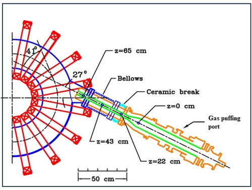
STOR-M is a small iron-core tokamak built for studies of plasma heating, anomalous transport, and development of novel operation modes and advanced diagnostics (Citation6). Basic diagnostics includes measurement of line-averaged electron density using a 4 mm microwave interferometer, plasma current using a Rogowski coil, loop voltage using a single loop coil, soft X-ray emission using photo diode arrays, HXR emission using a combination of a scintillator and photo multiplier tube (PMT), and visible plasma emission intensity waveform using a monochromator and a PMT. A low-resolution spectrometer is used to measure the plasma emission spectra for the main (hydrogen) and impurity species in the plasma. One of the four fast gas puffing (GP) valves, originally used for operation of the University of Saskatchewan Compact Torus Injector (USCTI), was repurposed to puff argon gas into STOR-M discharges. Figure shows the location of the gas valve on USCTI with respect to the STOR-M tokamak. The distance between the GP valve to the edge of the STOR-M plasma is approximately 1.3 m. The GP valve is activated by passing a capacitor discharge current through a pancake-like coil which couples the electromagnetic force to a sealing disk, opening the valve for a short period of time. The amount of the gas injected is controlled by the capacitor bank voltage. Although the response time of the GP valve is short (< 1 ms), it takes some time for the gas to diffuse into the STOR-M discharge through the gap between the inner and outer coaxial electrodes in USCTI.
Figure 1. Location of the argon gas puffing port on the USCTI injector with respect to the STOR-M tokamak. The puffed gas diffuses through the small gap between the two coaxial electrodes before entering the tokamak discharge.
Direct electron temperature measurements are not available on the STOR-M tokamak. However, the electron temperature can be estimated by the classical Spitzer resistivity. The measured plasma current and loop voltage are used to calculate the resistivity and to infer Spitzer temperature using the following equation:
where Tσ is the electron temperature in electron volts,
the Coulomb logarithm, and
the effective charge number of ions. R = 46 cm and a = 12 cm are the major and minor radii of the tokamak.
and
are measured plasma current and loop voltage, respectively. Assumptions, such as the effective charge of ions, must be made to use the above formula for STOR-M.
3. Results and discussion
Figure shows the waveforms of some key plasma parameters for a typical slide-away hydrogen discharge (shot number 358610) in STOR-M without argon gas puffing. The parameters shown are (from the top of the Figure), plasma current (), loop voltage (
, hydrogen line emission intensity (
), Spitzer temperature (
, HXR emission intensity, plasma horizontal displacement (ΔH), hydrogen gas valve (GV) control voltage pulses (
), line-averaged electron density (
), and the global energy confinement time (τ) estimated by the measured electron density, Spitzer temperature, and the ohmic heating power. The hydrogen gas valve is activated by voltage pulses through the piezo-electric effect and is independent of the argon GP valve. The first short hydrogen GV control voltage pulse injects hydrogen gas shortly before the STOR-M discharge to facilitate quick breakdown and the second long and high-amplitude pulse is used to terminate the discharge and to achieve ‘soft-landing’ of the plasma current. Without the last GV puffing pulse, STOR-M discharges may experience uncontrolled disruption withsudden termination of the plasma current and the induced high voltage may damage some parts of the ohmic heating coils. Three more pre-programed GV control voltage pulses may be added between the two pulses shown in to control the electron density during the discharge. Without those extra GV control voltage pulses, the electron density decreases steadily, a feature of ‘slide-away’ discharges purposely produced for this experiment. Most of the plasma parameter waveforms shown in remain relatively stable without sudden changes. It can be seen that HXR emission emerges when the electron density drops to about
. The staircase-like density waveform is due to the finite resolution of the fringe counter circuit which detects the zero-crossing of the oscillating interference signals from the interferometer. The resolution of the density measurement is
/step. HXR emission is produced when some unconfined runaway electrons impact on the chamber wall. Simultaneous increase of the hydrogen
line emission may be related to the increased recycling of hydrogen gas released from the wall due to the impact of runaway electrons.
Figure 2. A typical density slide-away hydrogen discharge in STOR-M (shot number 358610).
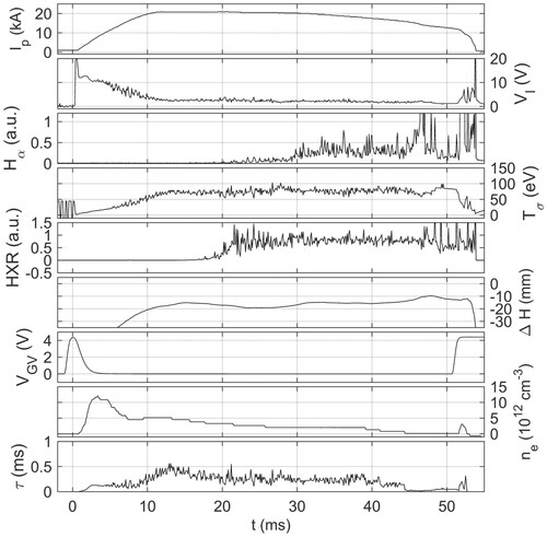
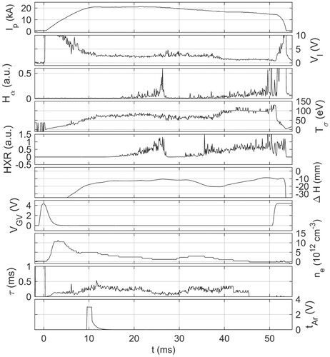
Figure shows a slide-away discharge (shot number 358717) with argon puffing at t = 10 ms. The last curve at the bottom of Figure is the trigger signal to activate the argon GP valve. The trigger pulse width and amplitude are fixed, independent of the amount of argon gas puffed (which is controlled by the capacitor bank voltage). Again, both HXR and hydrogen line emission signals emerge when the electron density decreases to a low level. At t∼26 ms, both the HXR and line emission intensities drop sharply. At t∼29 ms, the density starts to increase by a step. The density could have increased early, but the exact time cannot be determined due to the finite resolution of the density measurement. At t∼35.5 ms, the electron density decreases again, and the discharge seems to enter another phase with the following features: (a) reduced loop voltage, (b) increased Spitzer temperature, and (c) recovered HXR and
line emission intensities. The observed increase in the Spitzer temperature and decrease in the loop voltage following the suppression of HXR emission may be attributed to thermalization of the runaway electrons or to the improved confinement.
Figure 3. A density slide-away discharge with a large amount of argon puffing at 10 ms following the start of the STOR-M discharge (shot number 358517).
The amount of argon puffed and the trigger time during the slide-away discharges have also been varied. A relatively small amount of argon gas puffing has little effect on the already generated runaway electrons in the discharge. At slightly higher amount of argon puffing above a threshold, runaway electrons can be considerably suppressed. The waveforms of plasma parameters for another discharge (No. 344707) are shown in Figure with argon puffing at a later time (t = 24 ms). Suppression of HXR emission, increase in Spitzer temperature, and drop in loop voltage occur concurrently at t = 40 ms, 16 ms after argon puffing. Unfortunately, density measurement for that discharge was not available due to faulty microwave detectors. However, the discharge conditions were similar to those in two other discharges shown in Figures and . Therefore, a density slide-away discharge may be assumed for this discharge. This assumption can be confirmed by other signals such as the timing of the appearance of HXR emission. For cases with very strong argon gas puffing, the discharge is terminated earlier at the time of gas puffing, due to excessive increase in the electron density, similar to programed discharge termination by hydrogen gas puffing in STOR-M.
Figure 4. A discharge with a smaller amount of argon gas puffing at 24 ms following the start of the STOR-M discharge (shot number 344707). The density measurement was not available for this discharge due to faulty microwave diodes.
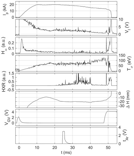
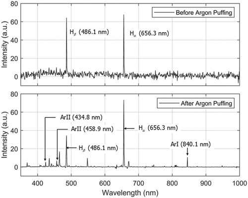
In our experiments, suppression of HXR appears to occur with a long delay of 16 ms for argon puffing both at 10 ms in Figure and at 24 ms in Figure . This long delay does not seem to correspond to the time for the gas to diffuse from GP into the STOR-M plasma as observed in a previous experiment with the same experimental setup and the same type of GP valves. In that experiment the electron density was maintained initially at about and the density began to increase with a delay of about 3 ms after very strong hydrogen gas puffing (Figure in ref. (Citation7)). The possible mechanism involved in the additional 13 ms delay for argon gas puffing to suppress HXR is unknown at this point. Attempts have been made to clarify the mechanism without conclusions. The first attempt was made by investigating the argon line emission from plasma using a low-resolution Ocean Optics spectrometer (Red Tide USB650). The spectrometer can take several spectra during the STOR-M discharge. The minimum integration time of the spectrometer is 3 ms. However, the timing between taking consecutive spectra cannot be accurately determined. Figure shows two spectra taken roughly before and after argon puffing during a discharge (shot number 356007), without knowing the exact integration time windows for the spectra. Two hydrogen emission lines can be identified before argon gas puffing. After argon puffing several possible argon emission lines, along with those from other unidentified impurities, can be identified. In another attempt, the GP valve was directly mounted onto a port on the STOR-M main chamber, supposedly reducing the gas diffusion time from the argon GP valve to the plasma in STOR-M. However, conclusive results on the time delay were not obtained.
Figure 5. Plasma emission spectra before and after argon puffing (shot number 356007).
4. Conclusions
Density slide-away discharges in the STOR-M tokamak have been produced to study the effects of argon puffing on runaway electrons. It has been observed that HXR emission, assumed to be caused by the impact of runaway electrons on the chamber wall, emerges only when the density decreased to a low level. After 16 ms following argon puffing, sudden decrease in the HXR and emission intensities has been observed. Coinciding with the suppression of runaway electrons, or shortly thereafter, an increase in the Spitzer temperature and decrease in the loop voltage are also observed. The temperature increase may be related to thermalization of runaway electrons and/or improved confinement induced by argon puffing. The anomalously long delay between argon puffing and suppression of runaway electrons remains a topic of future research on STOR-M.
Disclosure statement
No potential conflict of interest was reported by the author(s).
Additional information
Funding
References
- Whyte, D. G.; Jernigan, T. C.; Humphreys, D. A., et al., Phys. Rev. Lett. 2002, 89, 055001-1.
- Bakhtiari, M.; Kawano, Y.; Tamai, H., et al., Fast Plasma Shutdown Scenarios in the JT-60U Tokamak Using Intense Mixed gas Puffing. Nucl. Fusion 2002, 42, 1197.
- Knoepfel, H.; Spong, D.A. Runaway Electrons in Toroidal Discharges. Nucl. Fusion 1979, 19, 785.
- Krall, N. A.; Trivelpiece, A. W. Principles of Plasma Physics. San Francisco Press: San Francisco, 1986.
- Bellan, P. M. Fundamentals of Plasma Physics. Cambridge University Press: Cambridge, 2006.
- Hirose, A.; Xiao, C.; Mitarai, O.; Morelli, J.; Skarsgard, H.M. Phys. Canada 2006, 62, 111–120.
- Xiao, C.; Hirose, A.; Sen, S. Phys. Plasmas 2004, 11, 4041.