ABSTRACT
Linear, quadratic, and artificial neural network (ANN)-based metamodels were developed for predicting the extent of anthrax spore inactivation by chlorine dioxide in a ventilated three-dimensional space over time from computational fluid dynamics model (CFD) simulation data. Dimensionless groups were developed to define the design space of the problem scenario. The Hammersley sequence sampling (HSS) method was used to determine the sampling points for the numerical experiments within the design space. A CFD model, comprised of multiple submodels, was applied to conduct the numerical experiments. Large eddy simulation (LES) with the Smagorinsky subgrid-scale model was applied to compute the airflow. Anthrax spores were modeled as a dispersed solid phase using the Lagrangian treatment. The disinfectant transport was calculated by solving a mass transport equation. Kinetic decay constants were included for spontaneous decay of the disinfectant and for the reaction of the disinfectant with the surfaces of the three-dimensional space. To enhance the mixing of the disinfectant with the room air, a momentum source was included in the simulation. An inactivation rate equation accounted for the reaction between the spores and the disinfectant. The ANN-based metamodels were most successful in predicting the number of viable bioaerosols remaining in an arbitrary enclosed space. Sensitivity analysis showed that the mass fraction of the disinfectant, inactivation rate constant, and contact time had the most influence on the inactivation of the spores.
This investigation presents a framework for the development of user-friendly models; metamodels for the prediction of the number of viable spores remaining in an indoor room during disinfection from accurate but time-consuming CFD studies. During any decontamination event, to know when to stop pumping in the disinfectant and to know what level of log reduction of the spores have been achieved before even starting decontamination would provide valuable guidance. The neural network based metamodels can be applied to obtain quick and relatively accurate answers. This would be necessary when immediate information is required during emergencies.
INTRODUCTION
The deliberate release of anthrax spores, which occurred shortly after the events in September 11, 2001, resulted in 22 cases of anthrax infection and five deaths. This was a major factor in increasing national concerns for biological agent releases in the interior of building spaces.Citation1 Biological agents have a high potential for causing massive civilian casualties.Citation2 Most biological warfare agents, whether replicating (infectious) agents or derived toxins, have been weaponized for an aerosol assault.Citation3 This mode is most likely to inflict widespread disease.Citation3 Chlorine dioxide gas was used as the disinfectant during the decontamination of the Capitol Hill, Washington, DC.Citation4 After the 2001 anthrax attacks, the decontamination effort costs were 100 million dollars.Citation5 Decontamination of large indoor spaces and buildings following release of biological agents is challenging, as the response to the fall 2001 anthrax-release events indicate. The ability to efficiently and rapidly decontaminate rooms/buildings is limited by the lack of quantitative understanding of the behavior of biological agents and decontaminants in relation to building geometry, airflow pattern, and surface properties. Room decontamination also has significance in medical situations and laboratory design.
Numerous studies have been done regarding indoor airflow and particle transport in ventilated buildings. Lu et al.Citation6 conducted experiments measuring particle concentrations in the two-zone room and validated their developed fluid dynamics model (CFD) model. Zhao et al.Citation7 looked at the effect of displacement and mixing ventilation on particle concentration and deposition rate. CFD was used to compare traditional air displacement and under floor air distribution systems, which provided more detailed information at a lesser expense than experimental studies.Citation8 Others have developed CFD models for larger buildings with multiple roomsCitation9.Citation10 and have done experimental studies looking at the effect of room furnishings on particle deposition.Citation11 Historically, CFD modeling efforts have focused primarily on the simulation of airflow and dispersion of particles in apartment and buildings, not on disinfectant transport, interaction with bioaerosols, and decay in indoor air. Reshetin and RegensCitation2 conducted simulation modeling of anthrax spore dispersion in a 50-story, high-rise building. The modeling results showed that a relatively small volume of aerosolized spores has the potential to disperse quickly throughout the high-rise building. Stuart and WilkeningCitation5 investigated different mathematical models used to predict environmental degradation of the viability of potential bioweapons agents such as anthrax spores. The models behaved similarly at short times, <30 min; for longer-time phenomena, the different models gave vastly different predictions.Citation5 Experimental studies on ClO2 gasCitation12 Citation–15 have examined its efficiency in decontamination and have tried to understand its interaction with indoor surfaces.
Past studies provide detailed information and insight into the multiple factors influencing the dispersion of particles in a room, about spore dispersion and decay in buildings and about disinfectant transport and decay. The modeling results, CFD or otherwise, indicates how many particles remain in the room over a certain time period and do not incorporate disinfection. During any decontamination event, to know when to stop pumping in the disinfectant and to know what level of log reduction of the spores have been achieved before even starting decontamination would provide valuable guidance. But to obtain such accurate and quick information on the degradation of the spores would require extensive experimental work and the development of accurate but time consuming models such as a CFD model, specific to the scenario. This would be time consuming and require highly skilled personnel. This paper develops a framework for devising a user-friendly model that incorporates all the different aspects of the problem and is capable of predicting reasonably accurately and quickly how many viable spores remain during a decontamination event and in an emergency in an indoor space. Such a user-friendly model is known as a metamodel. “A metamodel serves as a surrogate or substitute for the more complex and computationally intensive simulation model” and was first proposed by Blanning.Citation16 Metamodeling allows for wider exploration of the problem parameters, improves the understanding of the model to be generated, and enables further studies for solution optimization systems.Citation17 – Citation19
In this study a comprehensive three-dimensional CFD model was developed and applied to numerically simulate the transport of the bioaerosols (e.g., spores of Bacillus anthracis) and their inactivation by a decontaminant (chlorine dioxide). Linear, quadratic, and artificial neural network (ANN)-based metamodels were developed and compared for predicting the number of viable bioaerosols remaining in an arbitrary enclosed space after sometime when a specific disinfectant has been applied. ANNs have increasingly been used instead of the conventional regression models to develop metamodels. This is because ANNs offer an alternative approach to conventional mathematical models for modeling complex systems. It supports multiple inputs and outputs and is capable of efficiently approximating any nonlinear function to an arbitrary degree with a single hidden layer. Recently ANN were trained and tested for optimizing ventilation systems in office environments.Citation20 They were also applied for the prediction of particle number and dispersion in any arbitrary indoor environments and performed better than linear and quadratic model forms.Citation21 They have been used to model the disinfection of waterborne bacteria,Citation22 for predicting ground level ozone giving residents forecasts in advanceCitation23 Citation Citation Citation–26 and for predicting the extent of groundwater contamination.Citation17
METHODOLOGY
The development of the metamodel involved the following steps: (1) identifying the input variables and the objective(s) (problem description); (2) choosing an experimental design technique to generate scenarios for efficient sampling of the design space (design space of the input variables); (3) conducting numerical experiments using CFD (development of the CFD model); and finally (4) testing and choosing the form of the meta model (determination of the metamodel form).
Problem Description
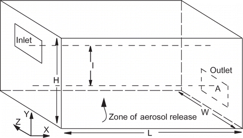
The geometry of the three-dimensional (3D) room and the aerosol release are shown in , which is representative of the problem scenario. The problem consists of three parts: airflow, aerosol transport and inactivation, and disinfectant transport and decay. To define the problem, 18 dimensional variables were selected. The details of the variables have been given in .Citation27 The assumptions are that the room is bare of any furnishings or partitions and infiltration and exfiltration is negligible. Air flows in and out of the room through the inlet and outlet located at the opposite ends of the room. Spores are released from an arbitrary location in the room. For a specific period of time the spores are allowed to disperse in the room before a mixture of air and a disinfectant is released through the room inlet.
Table 1. List of variables
In a functional form the relationship between the variables in can be written as follows where is the normalized number of viable spores remaining in the room,
By applying Buckingham Π theorem,Citation28 14 dimensionless groups are obtained from Equationeq 1:
Through dimensional analysis the dimensionality is reduced to a function that relates the 14 dimensionless groups. Rearranging the 13 dimensionless groups on the right hand side of the Equationeq 2 leads to Equationeq 3, where Q
mix (m3/sec) is the volumetric flow rate and θ (sec) is the residence time of the room calculated from , where V(m3) is the volume of the room. The dimensionless groups
and
are the same as the groups developed in previous studies by Hoque et al.Citation21,Citation27: the first four groups are the normalized length scales of the room; the last two normalizes the spore properties, particle diameter by the length scale of the room, and the spore density by the fluid density.
is similar to the Reynolds number.
is the ratio of the time the spores are in contact with only air and the residence time of the room.
is the ratio of the time the spores are in contact with the air disinfectant mixture to the residence time of the room. The dimensionless groups
account for the relationship between the decay rates of the disinfectant and the inactivation of the spores and the residence time of the room.
To determine the form of the function in Equationeq 3, accurate numerical investigations are necessary.
Design Space of the Input Variables
The design space of the 13 input dimensionless groups identified above has to be explored to extract the maximum information about the relationship between the output, and the input groups. However due to the computational cost of running the CFD model, the experimental design must efficiently explore the design space. First the boundaries of the design space would have to be determined. To determine the boundaries of the design space, a maximum value and a minimum value have to be assigned to the individual dimensional variables. The focus of the current study was to determine the effects of the variables introduced due to inactivation and decay. To ensure this was done efficiently, other dimensionless groups that did not involve the variables
, k
in, k
s, k
b, θ, and Q
mix were fixed at a constant value. The effect of the other dimensionless groups has been reported in a study by Hoque et al.Citation21 The geometry of the room was fixed with dimensions of
. The inlet and outlet area, A, was 0.5 m2. The minimum mass fraction assigned to chlorine dioxide,
, was 500 ppm and the maximum was 2000 ppm, whereas contact time of the spores, τc, with the disinfectant was ranged between 3 and 15 hrs. These estimates were based on the concentrations applied and the required length of time when disinfecting the Hart Senate Office Building, mail packages, and office building in Boca Raton, Florida.Citation29 The range for k
s was determined from the estimated deposition velocities of chlorine dioxide on different surfaces.Citation13 The reaction between decontaminants or pollutants and the indoor surfaces is characterized by mass transfer coefficients, which are referred to as deposition velocities.Citation30,Citation31 The range for k
b was estimated based on decay constants calculated from the regression analysis of the data obtained from experimental studies.Citation12235Citation14 The value for k
in was kept constant.Citation12,Citation14 Based on these values, the corresponding dimensionless groups in Equationeq 3 were evaluated and the minimum and maximum levels chosen. shows the minimum and maximum values of these dimensionless groups, labeled x
1 to x6, thus defining the boundaries of the design space. Sampling points at locations of this design space were next determined.
Table 2. Range for each of the dimensionless groups
Typically for physical experiments, classical experimental methods have been applied to determine the points or levels at which experiments would be conducted.Citation18,Citation32 For computer experiments, space-filling designs have been suggested as the better alternative.Citation32 Four types of space-filling designs have been used more often in the literature: orthogonal arrays, Latin hypercube designs, Hammersley sequences, and uniform designs.Citation18 Hammersley sequence sampling (HSS) has been found to provide better uniformity than Latin hypercube designs for a multi dimensional unit hypercube.Citation18,Citation33 It is an example of a low-discrepancy sequence. The concept of discrepancy is applied to choose the appropriate quasi-Monte Carlo sequence, of which the Hammersley sequence is an example. Twenty-five data points were generated for each dimensionless group through HSS.Citation32,Citation33 gives details of the data. This was implemented in MATLAB.Citation34 To obtain a more even distribution of the sampling points, two other conditions were imposed when sampling, one the correlation of the generated points for each input group less than 0.3 and the median of the generated points for each group was within 10% of the midpoint of the range of each of the dimensionless groups. The output, N/N 0 was then determined by conducting numerical experiments at those locations.
Table 3. Design space of the chosen six dimensionless groups
Development of the CFD Model
The geometry of the CFD model is the 3D room as shown in . The dimensions assigned to the room were along the x-axis (longitudinal), y-axis (transverse), and z-axis (vertical), respectively. Air enters the room through the supply section having dimensions,
located at a height higher than the exit section
, which is located at the opposite wall of the room. The CFD model was utilized to predict flow fields, spore trajectories, disinfectant concentration, and decay and inactivation of the spores. The complete model comprised submodels for fluid flow and particle transport; disinfectant transport and spore inactivation. To ensure a more uniform gradient of the disinfectant concentration in the room, a momentum source was introduced for increasing turbulence and to enhance mixing.Citation35 This was simulated by adding force terms, axial, normal, and circumferential to the momentum equation. The force was calculated from the equation,
where
is the mass displaced and
is the velocity difference between the fluid velocity and the rotational velocity specified for the momentum source.Citation35 The numerical simulations were conducted using CFD-ACE+,Citation36 which allowed transient particle calculations.
Airflow Model
The 3D indoor turbulent flow was modeled here by Large Eddy Simulation (LES). LES is a technique of complexity between direct numerical simulation (DNS) and Reynolds averaged Navier-Stokes (RANS). DNS is the most accurate of the three methods but it requires the most computing power (high-speed and large-capacity computer) for airflow simulation in a building.Citation37 RANS modeling applies different turbulence models to calculate the Reynolds stresses and close the system of Navier-Stokes equations. It generates the mean velocity field and not the instantaneous velocity field. The latter influences particle dispersion significantly. LES generates instantaneous flow information required for particle simulation.Citation37 Citation,38 In LES, small-scale turbulence is filtered out from the Navier-Stokes equations, and a model is used to evaluate small scales. The filtered Navier-Stokes equations are solved for the large-scale motion, which is responsible for most of the momentum and energy transport. The filtered or resolved quantity is denoted by an overbar. The small scales are from subgrid-scale models, which in turn influence the large eddies. For incompressible flow of a Newtonian fluid, the filtered Navier-Stokes equations are
The effect of the small scales appears through the subgrid-scale (SGS) stress term, .Citation39 The most commonly used subgrid-scale stress model is the Smagorinsky model, which is an eddy-viscosity model of the form,
. The subgrid-scale stresses are related to the large-scale strain rate tensor by
. The eddy viscosity,
is obtained from the algebraic model, Equationeq 6, where
is the grid size and
is the Smagorinsky constant. In the Smagorinsky model, the eddy-viscosity coefficient is maintained constant for the entire flow domain.
Particle Model
The particle trajectories were computed using the Lagrangian approach. The trajectory of the particle was determined by solving the following set of equations where is the velocity of the particle of mass m at location
.
is the net gravitational force on a sphere and is represented by Equationeq 10. The drag force,
, is represented by the Equationeq 11, where
drag coefficient,
velocity of airflow, and
Cunningham correction factor.
The Cunningham correction factor is a function of the Knudsen number and is determined from , where λ is the mean free path. For particle motion with Reynolds' number less than 0.1,
, when the Reynolds' number is from 1000 to
,
. In between,
is calculated from:
.Citation40
Disinfectant Transport and Decay
Disinfection is a process designed for the deliberate reduction of the number of pathogenic microorganisms. In this study the transport and decay of ClO2 disinfectant has been simulated when it is released into the inlet air stream of a room. Disinfectant mass fraction was calculated from the convective/diffusive mass transport equation:
where is concentration of the species, ClO2, μ
t
is turbulent viscosity,
is the velocity vector,
is the Cartesian coordinate vector with index
, D is the molecular diffusivity of the species. Chlorine dioxide decay in the room space,
, was modeled as a pseudo-first-order reaction, Equationeq 13, where k
b (sec−1) is the decay rate constant:
Chlorine dioxide reaction with surfaces was modeled as a first-order reaction, as shown in Equationeq 14.
The rate of reaction based on unit surface area available for the current case was written as
where volume of the indoor space (m3),
surface area (m2),
over all gas transfer coefficient (sec−1), and k = mass transfer coefficient or deposition velocity (m/sec).
Kinetics of Inactivation
The disinfection process involves the contact of a biological agent (for example, B. anthracis spores) with a dose of disinfectant (ClO2) for a sufficient time period to achieve a desired level of inactivation. Throughout the disinfection contact period, both the disinfectant and viable spore concentrations would decrease. An inactivation rate equation for the reaction between viable anthrax spores and the disinfectant were derived based on the study of kinetic reactions involving chlorine dioxide at a fixed temperature and relative humidity.Citation14 This study reported kinetics consistent with a simple Chick-Watson relationship.Citation41
where r in is the reaction rate defined above, T is the temperature, and RH is the relative humidity. The concentration C (decontamination agent) is a function of position within the contaminated zone and f is the viability of the anthrax spores. Thus the inactivation rate equation for the reaction between anthrax particles and the disinfectant has been generalized in this study as
where k in is reaction constant, n is 0.5, C is the concentration of the disinfectant at the location of the spore, and f is the viability of the anthrax spores. EquationEquation 17 was included into the simulation to track the viability of the spores.
Boundary Conditions and Numerical Methods
The control-volume method was employed to discretize the governing equations. A blended second-order upwind scheme was applied for the convective-diffusive terms and the implicit Euler scheme was used for the temporal terms in the governing equations. Dirichlet boundary conditions were specified at the inlet for the velocity components. The outlets were designated as pressure boundaries, with Dirichlet conditions specified for pressure and Neumann conditions (i.e., zero normal gradients) specified for all other dependent variables. The boundary conditions at the walls of the room represented no-slip conditions. ClO2 enters the room mixed with the inlet air. Inlet mass fraction of ClO2 was specified based on the case. The spores were initialized, slightly above the floor with a small upward velocity of 0.001 m/sec. When the spores reached the outlets, the calculation of the trajectories were terminated. When a spore strikes a surface, it was assumed that it lost half of its energy. This assumption accounted for the different types of surfaces, that is, walls or carpeted floor. Below is a summary of the assumptions:
| 1. | Incompressible and isothermal conditions | ||||
| 2. | No heat and mass transfer between the air and the particles | ||||
| 3. | The coefficient of restitution was set to 0.5 | ||||
| 4. | Spherical, solid, and neutral particles | ||||
| 5. | Airborne particles have no influence on the surrounding airflow field, that is, one-way coupling | ||||
| 6. | Negligible particle-particle interactions | ||||
| 7. | Negligible resuspension. | ||||
Simulation Steps
Time-dependent flow fields and particle trajectories were simulated for the 25 cases generated by HSS. For each case, the inlet velocity, chlorine dioxide mass fraction, and kinetic rate parameters were first determined, and the air changes per hour were kept within a range of 1 to 10. This range encompasses the permitted air changes per hour for offices, residences, and hospitals. At the end of each simulation, the change of the viability of the spores was determined from the moment spores were released to the moment the simulation was terminated. The steps in the simulation were as follows:
| 1. | The flow field in the room was first established for one residence time. | ||||
| 2. | 100,000 spores were released and tracked for one residence time. | ||||
| 3. | Chlorine dioxide was then mixed with the inlet air and released into the room and the momentum source turned on. | ||||
| 4. | The simulation was continued until at least a 5 log reduction of the viability of the B. anthracis spores was predicted. | ||||
For all cases, nonuniform grids were used with denser grids near the walls. The smallest mesh size was 0.01 m. The time step was 0.05 sec. The 25 cases needed 3 months of computational time to complete requiring on an average, 80 hrs for each case on a personal desktop computer with a 3-GB RAM and 3-GHz processor.
Determination of the Metamodel Form
Determining the architecture of the metamodel is an iterative process that involves choosing a form of the metamodel to represent the behavior of a given phenomenon. Then the parameters in that form are calibrated to the data to determine the best fit, and the generalizability (e.g., by cross-validation) assessed. Three metamodel forms were tested. They were the linear model, quadratic model, and neural networks. The sum of square of errors, , was calculated for each model form where e is the difference between the metamodel output and the CFD simulation output.
Linear and Quadratic Models
EquationEquation 18 represents the multiple linear regression model where are the predictor variables, y is the response,
's are the regression coefficients, and
is a random variable assumed to be independent and identically distributed as
and is referred to as the random error term of the model.
The regression coefficient represents the expected change in response y per unit change in x when all the remaining independent variables are held constant. The linear model is linear because the expected value of y is a linear function of weighted sums of the
's. The linear regression model is attractive because the value of the
's can be estimated by analytical solution through the method of least squares. The quadratic form of the model as shown in Equationeq 19 also includes the squared terms of the predictor variables.
Neural Networks
Neural networks grew out of research attempting to mimic the problem solving capacity of biological neural systems via learning and generalization. There are different model types of neural networks.Citation42 The feed-forward multilayer perception (MLP) model type is the most widely used network and it consists of an input layer, one or more hidden layers, and an output layer. In each layer a specific number of nodes with an activation function are placed. Mathematically, a 3-layer ANN with n, m, and p as the number of input, hidden, output nodes, respectively, is based on the equation:
where are the output values and
are the input values of the network,
are the connection weights between the input and the hidden layers,
are the connection weights between the hidden layer and the output layer, and f is the activation function. The activation functions could be linear, sigmoid, or hyperbolic tangent. The output of one node contributes to the input to the nodes in the next layer. The weights and biases are determined by optimization methods.Citation17
Citation,42 The Levenberg-Marquardt numerical optimization technique was employed to update the weights and biases in the network.Citation34,Citation43
Model Assessment
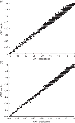
To assess goodness of fit of a model, the following diagnostic plots were employedCitation44: standardized residual versus metamodel-predicted values, yk , and CFD results versus metamodel-predicted values, yk . If the plot of model residuals versus model predictions shows a distinct nonrandom pattern then the equation or model is inappropriate. A plot of observed values (CFD results) versus metamodel predictions should be close to a 45° line if the model is accurate.Citation44
For models with differing number of parameters, it has to be determined whether an increase in model parameters is justified by an improvement in fit. To determine this, an F testCitation45 was performed on the basis of
In Equationeq 21
df is the degrees of freedom, that is, number of data points minus number of parameters (subscript “1” refers to fit with fewer parameters). Critical values for the F distribution were obtained by consulting a standard table using and
degrees of freedom. If
, then it was concluded that increasing the number of parameters improved the network performance significantly.Citation45
Cross-validation
One of the principal characteristics of a neural network is that if it is provided with a set of inputs and known outputs for a given system, the network organizes itself internally, that is, alters the various weights such that it predicts the expected output for any other given input. The internal process of self-organization of the system is training. A network is overtrained when the network focuses on the characteristics of individual data points rather than capturing the general patterns present in the entire training set. If a network has learned well, then it should classify an unseen pattern correctly and the net is said to generalize well. Cross-validation is a procedure applied to avoid overtraining and for selecting the optimal network. The cross-validation approach consists of a cyclic allocation of the data for training and testing and allows the use of all the data set for testing.Citation46 Citation,47 The network is trained for a select set of data and tested against the remaining data set. The procedure is repeated until all the data are used. The SSE is computed for both training and testing for optimum convergence. Initially the SSE decreases with increasing number of hidden nodes for both training and testing. But when the network becomes overtrained, the SSE for the testing will start to increase, indicating that increasing the number of nodes is now reducing the generalizing ability of the network. At this point, the number of nodes in the hidden layer is not increased any further.Citation22 Citation,48 The cross-validation method was applied to avoid overtraining and to select the final model form for the neural networks.
RESULTS AND ANALYSIS
Computational Results
The CFD model was validated against experimental dataCitation6
Citation,49 and was found to be in excellent agreement. Details of the validation studies of the CFD model have been given in Hoque et al.Citation27 Grid sensitivity analysis was conducted to obtain grid-independent solutions.Citation35
lists the values of the six dimensionless groups for the 25 cases. For all cases, the rotational velocity of the momentum source was kept constant.Citation35 For each case, the decrease of viability of the spores was tracked over time and recorded for every time step. In all 25 cases, the simulations were terminated well before the anticipated time determined from as greater than 5 log reduction was achieved before τc. For example, the theoretical mean residence time for case 14 was 728 sec and for case 22 it was 1269 sec. Spores were tracked for one residence time and then the disinfectant released. In and , the plot of the normalized number of viable particles remaining in the room over time for cases 14 and 22 has been shown.
Figure 2. Plot of normalized number of viable particles remaining in the room over time; ClO2 was injected at 0 sec (case 14).
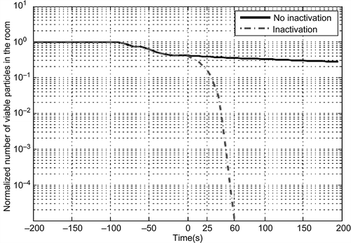
Figure 3. Plot of normalized number of viable particles remaining in the room over time, ClO2 injected at 0 sec (case 22).
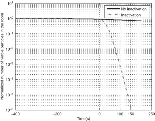
In the plots, 0 sec indicate when ClO2 was released into the room. The plots have two lines, one showing the behavior of the spores when no inactivation is happening, that is, spore loss is only due to the airflow and the second line showing loss of spores due to both inactivation and convective flow. In both cases, the combined effect of inactivation and convective flow has the dominant effect, with a sharp decrease of the number of viable spores once disinfection has started. For case 14, nearly 5 log reduction was obtained within 60 sec of ClO2 release, whereas for case 22, a 5 log reduction was obtained after 130 sec. However, was calculated to be 4 and 11 hrs for cases 14 and 22, respectively. Hence, instead of
, for every case
was recorded for every time step, where
is the actual contact time between the disinfectant and the spores.
By recording 960 data points were obtained from these 25 cases. To map out the relationship and to develop predictive metamodels, the statistical and neural network toolbox of MATLABCitation34 was applied.
Linear and Quadratic Metamodel
EquationEquation 22 is the linear metamodel. The input dimensionless groups were log transformed, as well as the output, the normalized number of viable particles in the room, . x
6 represents
. The SSE for the linear model was 76222 with an R
2 of 0.55.
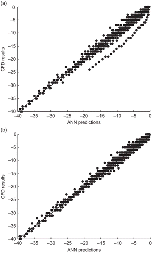
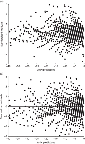
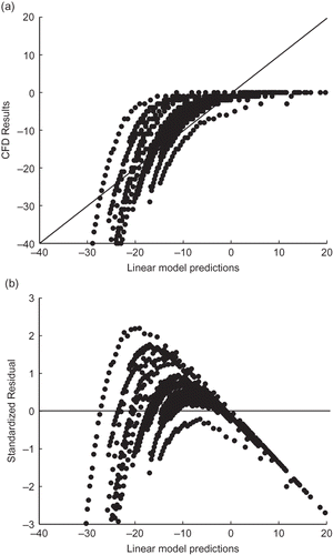
compares the predicted results from the linear model to the CFD-simulated results. Most of the data are not around the diagonal, indicating a lack of predictive ability by the linear model. is the plot of the standardized residuals against the predicted results from the model. The plot shows a trend and the data points are not evenly distributed about the horizontal axis at zero.
Figure 4. Linear model results. (a) CFD results against predicted results; (b) standardized residual plot.
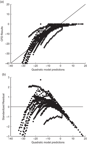
EquationEquation 23 is the quadratic metamodel. The R 2 for the quadratic model was 0.7, an improvement over the linear model. and show the residual plot and the plot of the predicted results from the quadratic model to the CFD results. The plots are similar to the plots obtained for the linear model, indicating the quadratic model is not suitable either.
Figure 5. Quadratic model results. (a) CFD results against predicted results; (b) standardized residual plot.
Neural Network
The neural networks developed have six nodes in the input layer corresponding to the six input dimensionless groups. One node is present in the output layer corresponding to the log normalized number of viable spores remaining in the room, . The chosen activation function was tangent-hyperbolic in the hidden layer(s). The purpose of training and testing the neural network is to identify the architecture that would be appropriate for use and to provide an assessment of the neural network performance. In this study two architectures were studied: one with single hidden layer and the second with two hidden layers. Theoretically the multiple hidden layer networks are not more powerful than single hidden layers but empirically networks with multiple hidden layers sometimes generalize better, with fewer parameters.Citation50,Citation51 For all cases, the neural network was trained until the sum of square of errors reached an assigned minimum value of 10−6 or remained constant at a low level for a number of iterations, 250,000. Increasing nodes leads to increasing number of adjustable parameters (weights and biases in the network). The maximum number of nodes included was such that the number of adjustable parameters did not exceed the number of data points in the training set.
Architecture with One Hidden Layer
The SSE for the neural network with one node in the hidden layer, ANN6-1-1 was 11,107 with an R
2 of 0.91. The number of adjustable parameters was nine in the neural network same as in the linear model. and show the plot of the neural network predictions for with two nodes (R
2 = 0.99) and three nodes (R
2 = 0.995) in the hidden layer, respectively.
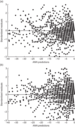
and show the corresponding residual plots. The performance of the neural network is significantly better than either the linear or the quadratic model for all the cases.
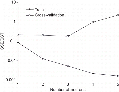
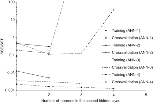
To avoid overtraining the network and to determine when to stop increasing the number of nodes, the cross-validation method was applied. The steps applied to do the cross-validation were as follows: out of the 25 cases in the set, data belonging to 24 cases were cases were used to train the networks and were then validated against the remaining data of one case. The SSE was recorded. This was repeated for all 25 cases and the total sum of squares calculated by adding the individual sum of squares. shows the results of the training and the cross-validation. In , the SSE for both training and cross-validation as the number of nodes was increased from one to five in the hidden layer has been plotted. When the number of hidden nodes increased from three to four, the cross-validation sum of squares increased and continued to increase when the number of hidden nodes was five. Hence the optimum network for the architecture with one hidden layer was ANN6-3-1 with 25 adjustable parameters.
Table 4. Change of SSE with increasing number of neurons for architecture with one hidden layer
Architecture with Two Hidden Layers
For the architecture with two hidden layers, the number of nodes in the hidden layers was adjusted such that the number of nodes in the second hidden layer was always less than or equal to the number of nodes in the first hidden layer. It has been shown that neural networks perform better when the second hidden layer does not have more nodes than the first hidden layer.Citation21,Citation51 The neural network, with one node in both hidden layers, ANN6-1-1-1, has 11 adjustable parameters. The SSE obtained was 10,989 (R 2 = 0.91). and show the plots of the network predictions for ANN6-2-2-1 and ANN6-3-2-1. and show the corresponding residual plots.
Figure 10. Standardized residual plot (a) for ANN6-2-2-1 predictions (b) for ANN6-3-2-1 predictions.
The SSE decreased to 649 (R 2 = 0.995) when the number of nodes in both hidden layers was increased to two. The adjustable parameters for this network, ANN6-2-2-1, were 23 less than the number of parameters in the single hidden layer architecture, ANN6-3-1, which has 25 but a higher sum of squares, 677.6. The architecture with two hidden layers appeared to be performing better than the architecture with one hidden layer. The number of nodes in the hidden layers was increased until there were four nodes in each hidden layer.
Cross-validation was then applied to determine the optimum network architecture. lists the sum of squares for both training and cross-validation for all the two hidden layered architectures tried. plots these values against increasing number of nodes in the second hidden layer. The plot shows that increasing the number of nodes in the first hidden layer resulted in an overall decrease in the sum of squares irrespective of the number of adjustable parameters. The cross-validation results show that for networks with three and four nodes in the first hidden layer, overtraining occurred when the nodes in the second hidden layer were increased after a certain point. The cross-validation decreased from network ANN6-2-1-1 to ANN6-2-2-1. Based on the cross-validation results, the two networks that had comparatively lower sum of squares were ANN6-4-2-1 and ANN6-4-3-1. An F test showed that increasing the number of adjustable parameters from 41 to 47 when going from ANN6-4-2-1 to ANN6-4-3-1 resulted in a significant decrease to the sum of squares. Hence the optimum network chosen was ANN6-4-3-1.
Table 5. Change of SSE with number of neurons (architecture: two hidden layers)
Figure 11. Change of sum of square of errors with increasing number of neurons in the second hidden layer; architecture with two hidden layers (number of neurons in the second hidden layer the number of neurons in the first hidden layer).
Between the final two architectures ANN6-3-1 and ANN6-4-3-1 the architecture with two hidden layers had a lower sum of squares for both training and cross-validation. Based on this and the very improved performance of the networks over the linear and quadratic metamodels, the final form of the metamodel chosen was the neural network ANN6-4-3-1.
Sensitivity Analysis of the Input Dimensionless Groups
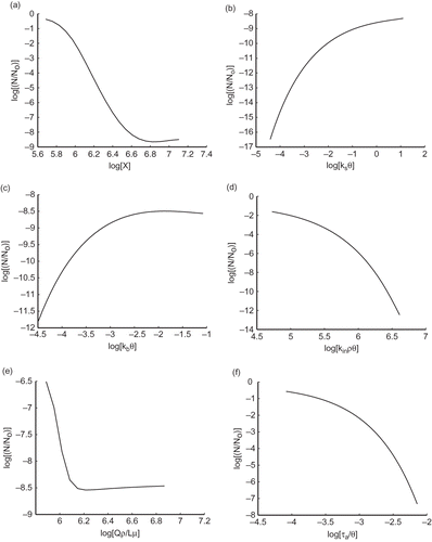
shows the sensitivity of the response, , when the magnitudes of each of the dimensionless groups were varied independently applying the neural network ANN6-4-3-1. The magnitudes of the dimensionless groups were varied within the logarithm of the specified range (). The change of
with increasing
has been plotted in . As the concentration of the disinfectant was increased, the number of viable spores decreased. The plots in –f are for the other five dimensionless groups. For the dimensionless groups with the decay rate constants k
sθ and k
bθ, the number of spores increases with increasing decay. This occurs because more of the disinfectant is removed due to self-decay or due to surface interaction resulting in lower availability of disinfectant for the inactivation of spores. In case of
, the number of viable spores decreased with increasing inactivation rate. Also, increasing contact time resulted in decreasing number of spores, as seen in . With increasing flow rate,
decreases and then the plot levels off for the dimensionless group
at the point where the number of viable spores in the room is approximately 20, indicating at some point the spores are not in the flow stream and are not being removed by increasing airflow.
CONCLUSIONS
Numerical experiments were conducted using CFD for generating data to develop metamodels capable of predicting the number of viable spores remaining in a room after starting disinfection using chlorine dioxide. A CFD model was developed to simulate the inactivation of B. anthracis spores released in a room by chlorine dioxide including the variables mass fraction of chlorine dioxide, , surface and bulk decay rate of chlorine dioxide,
, inactivation rate constant,
, and contact time,
, between spores and disinfectant. A momentum source was used in the room to enhance mixing of the disinfectant in the room. The CFD model was applied to simulate 25 cases generated applying HSS method.
The linear, quadratic, and neural-network-based metamodels were explored. The performance of the neural networks was significantly better than either linear or quadratic metamodel. Two types of architectures were explored for the neural networks: one with a single hidden layer, and the other with two hidden layers. Cross-validation was applied to determine the maximum number of nodes before overtraining occurred. ANN6-3-1 was the best neural network for the single hidden layer architecture. For the two hidden layer architecture, the best neural network was ANN6-4-3-1 based on the cross-validation sum of squares. The SSE obtained from the architecture with two hidden layers was lower than the SSE obtained from the architecture with one hidden layer. Hence the final form of the metamodel chosen was ANN6-4-3-1. Sensitivity analysis studies were then conducted using this network. The analysis showed that the bulk and surface decay rate had similar sensitivity towards the log reduction of the viability of the particles. Mass fraction of chlorine dioxide, inactivation rate constant, and contact time had the most influence, whereas flow rate appeared to have the least impact on the inactivation of the spores.
The study outlines a systematic method for developing metamodels for predicting inactivation of spores from CFD simulations. The results show that this method can be applied to gain a better understanding into the disinfection kinetics in the indoor spaces and with spores. The metamodel developed can be used for providing information during emergencies. More information regarding the surface chemistry of chlorine dioxide would help in increasing model accuracy. The methodology can also be expanded by including more variables into the model that would account for additional complexities in the space such as partitions, multiple zones, etc. The presence and type of furniture can be incorporated into the model by including parameters such as area occupied by furniture, different surface roughness values, and possible rate constants, etc. The modeling could also include as a variable the range of impact of the momentum source on the mixing of the disinfectant and the influence of the impact for different room geometries.
ACKNOWLEDGMENTS
The work described in this paper was supported by the L. D. Betz Environmental Engineering Endowment at Drexel University.
REFERENCES
- Inglesby , T.V. , O'Toole , T. , Henderson , D.A. , Bartlett , J.G. , Ascher , M.S. , Eitzen , E. , Friedlander , A.M. , Gerberding , J. , Hauer , J. , Hughes , J. , McDade , J. , Osterholm , M.T. , Perl , T.M. , Russell , P.K. and Tonat , K. 2002 . Anthrax as a Biological Weapon, 2002: Updated Recommendations for Management . JAMA , 287 : 2236 – 2252 .
- Reshetin , V.P. and Regens , J. L. 2003 . Simulation Modeling of Anthrax Spore Dispersion in a Bioterrorism Incident . Risk Anal. , 23 : 1135 – 1145 .
- Burrows , W.D. and Renner , E.S. 1999 . Biological Warfare Agents as Threats to Potable Water . Environ. Health Perspect. , 107 : 975 – 984 .
- Solazzo , C. , Erhardt , D. , Marte , F. , Von Endt , D. and Tumosa , C. 2004 . Effects of Chemical and Biological Warfare Remediation Agents on the Materials of Museum Objects . Applied Physics A , 79 : 247 – 252 .
- Stuart , A.L. and Wilkening , D.A. 2005 . Degradation of Biological Weapons Agents in the Environment: Implications for Terrorism Response . Environ. Sci. Technol. , 39 : 2736 – 2743 .
- Lu , W. , Howarth , T. Andrew , Adam , N. and Riffat , S.B. 1996 . Modelling and Measurement of Airflow and Aerosol Particle Distribution in a Ventilated Two-Zone Chamber . Build. Environ. , 31 : 417 – 423 .
- Zhao , B. , Zhang , Y. , Li , X. , Yang , X. and Hunag , D. 2004 . Comparison of Indoor Aerosol Particle Concentration and Deposition in Different Ventilated Rooms by Numerical Method . Build. Environ. , 39 : 1 – 8 .
- Lee , K. , Zhang , T. , Jiang , Z. and Chen , Q. 2009 . Comparison of Airflow and Contaminant Distributions in Rooms with Traditional Displacement Ventilation and Under-Floor Air Distribution Systems . ASHRAE Trans. , 115 : 306 – 321 .
- Chung , K.C. 1999 . Three-Dimensional Analysis of Airflow and Containment Particle Transport in a Partitioned Enclosure . Build. Environ. , 34 : 7 – 17 .
- Chang , T.-J. , Hseih , Y.-F. and Kao , H.-M. 2006 . Numerical Investigation of Airflow Pattern and Particulate Matter Transport in Naturally Ventilated Multi-Room Buildings . Indoor Air , 16 : 136 – 152 .
- Thatcher , T.L. , Lai , A.C.K. , Moreno-Jackson , R. , Sextro , R.G. and Nazaroff , W. 2002 . Effects of Room Furnishings and Air Speed on Particle Deposition Rates Indoors . Atmos. Environ. , 36 : 1811 – 1819 .
- Han , Y. , Applegate , B. , Linton , R.H. and Nelson , P.E. 2003 . Decontamination of Bacillus thuringiensis Spores on Selected Surfaces by Chlorine Dioxide Gas . J. Environ. Health , 66 : 16 – 20 .
- Hubbard , H. , Poppendick , D. and Corsi , R.L. 2009 . Chlorine Dioxide Reaction with Indoor Materials during Building Disinfection: Surface Uptake . Environ. Sci. Technol. , 43 : 1329 – 1335 .
- Jeng , D.K. and Woodworth , A.G. 1990 . Chlorine Dioxide Gas Sterilization under Square Wave Conditions . Appl. Environ. Microbiol. , 56 : 514 – 519 .
- Wood , J.P. , Ryan , S.P. , Snyder , E. Gibb and Serre , S.D. 2010 . Adsorption of Chlorine Dioxide Gas on Activated Carbons . J. Air Waste Manage. Assoc. , 60 : 898 – 906 . doi: doi: 10.3155/1047-3289.60.8.898
- Blanning , R.W. 1975 . The Construction and Implementation of Metamodels . Simulation , 24 : 177 – 184 .
- Tabach , E. El , Lancelot , L. , Sharour , I. and Najjar , Y. 2007 . Use of Artificial Neural Network Simulation Metamodelling to Assess Groundwater Contamination in a Road Project . Math. Comput. Model. , 45 : 766 – 776 .
- Wang , G.G. and Shan , S. 2007 . Review of Metamodeling Techniques in Support of Engineering Design Optimization . Trans. ASME , 129 : 370 – 380 .
- Broad , D.R. , Dandy , G.C. and Maier , H.R. 2005 . Water Distribution System Optimization Using Metamodels . J. Water Res. Plan. Manage. , 131 : 172 – 180 .
- Zhou , L. and Haghighat , F. 2009 . Optimization of Ventilation System Design and Operation in Office Environment, Part I: Methodology . Build. Environ. , 2009 : 651 – 656 .
- Hoque , S. , Farouk , B. and Haas , C.N. 2011 . Development of Metamodels for Predicting Aerosol Dispersion in Ventilated Spaces . Atmos. Environ. , 45 : 1876 – 1887 .
- Janes , K.R. and Musilek , P. 2007 . Modeling the Disinfection of Waterborne Bacterial Using Neural Networks . Environ. Eng. Sci. , 24 : 471 – 482 .
- Feng , Y. , Zhang , W. , Sun , D. and Zhang , L. 2011 . Ozone Concentration Forecast Method Based on Genetic Algorithm Optimized Back Propagation Neural Networks and Support Vector Machine Data Classification . Atmos. Environ. , 45 : 1979 – 1985 .
- Tsai , C.-h. , Chang , L.-c. and Chiang , H.-c. 2009 . Forecasting of Ozone Episode Days by Cost-Sensitive Neural Network Methods . Sci. Total Environ. , 407 : 2124 – 2135 .
- Wang , D. and Lu , W. 2006 . Forecasting of ozone Level in Time Series Using MLP Model with a Novel Hybrid Training Algorithm . Atmos. Environ. , 40 : 913 – 924 .
- Wirtz , D.S. , Gamal El-Din , M. , Gamal El-Din , A. and Idriss , A. 2005 . Systematic Development of an Artificial Neural Network Model for Real-Time Prediction of Ground-Level Ozone in Edmonton, Alberta . J. Air Waste Manage. Assoc. , 55 : 1847 – 1857 .
- Hoque , S. , Farouk , B. and Haas , C.N. 2010 . A Multiple Linear Regression Model Approach for Aerosol Dispersion in Ventilated Spaces Using Computational Fluid Dynamics and Dimensional Analysis . J. Environ. Eng. , 136 : 638 – 649 .
- Buckingham , E. 1915 . Model Experiments and the Forms of Empirical Equations . Am. Soc. Mech. Eng. , 37 : 263 – 296 .
- The National Pesticide Information Center. Anthrax Spore Decontamination Using Chlorine Dioxide. U.S. Environmental Protection Agency, 2007 http://www.epa.gov/pesticides/factsheets/chemicals/chlorinedioxidefactsheet.htm (http://www.epa.gov/pesticides/factsheets/chemicals/chlorinedioxidefactsheet.htm) (Accessed: August 17, 2009 ).
- Cano-Ruiz , J.A. , Kong , D. , Balas , R.B. and Nazaroff , W. 1993 . Removal of Gases at Indoor Surfaces: Combining Mass Transport and Surface Kinetics . Atmospheric Environment , 27A ( 13 ) : 2039 – 2050 .
- Morrison , G.C. and Wiseman , D.J. 2006 . Temporal Considerations in the Measurement of Indoor Mass Transfer Coefficients . Atmos. Environ. , 40 : 3389 – 3395 .
- Simpson , T.W. , Peplinski , J.D. , Koch , P.N. and Allen , J.K. 2001 . Metamodels for Computer-Based Engineering Design: Survey and Recommendations . Eng. Comput. , 17 : 129 – 150 .
- Diwekar , U.M. and Kalagnanam , J.R. 1997 . Efficient Sampling Technique for Optimization Under Uncertainty . AIChE J. , 43 : 440 – 447 .
- MathWorks . 2010 . MATLAB Version 7.10.0499Mathworks Inc., Natick, Massachusetts, U.S.A,
- Hoque , S. 2010 . Development of Computational Fluid Dynamics based Multiple Linear and Neural Network Metamodels for Bioaerosol Fate and Transport in Indoor Environments , Philadelphia : Drexel University .
- CFD-ACE+, Version 2007.2.25. ESI R&D Inc., Huntsville, Alabama, 2004 www.esi-cfd.com (http://www.esi-cfd.com)
- Beghein , C. , Jiang , Y. and Chen , Q.Y. 2005 . Using Large Eddy Simulation to Study Particle Motions in a Room . Indoor air , 15 : 281 – 290 .
- Tian , Z.F. and Tu , J.Y. 2007 . CFD Studies of Indoor Airflow and Contaminant Particle Transportation . Part. Sci. Technol. , 25 : 555 – 570 .
- Piomelli , U. 1999 . Large-Eddy Simulation: Achievements and Challenges . Prog. Aerospace Sci. , 35 : 335 – 362 .
- Hinds , W.C. 1999 . Aerosol Technology, Properties, Behavior and Measurement of Airborne Particles , 2nd , John Wiley and Sons .
- Gyurek , L.L. and Finch , G.R. 1998 . Modeling Water Treatment Chemical Disinfection Kinetics . J. Environ. Eng. , 124 : 783 – 794 .
- Bishop , C.M. 1995 . Neural Networks for Pattern Recognitions , Oxford : Clarendon Press .
- Hagan , M.T. and Menhaj , M.B. 1994 . Training Feed Forward Networks with the Marquardt Algortihm . IEEE Trans. Neural Networks , 5 : 989 – 993 .
- Devore , L.J. 2004 . Probability and Statistics for Engineering and the Sciences , California : Thomson, Brooks/Cole .
- Motulsky , H.J. and Ransnas , L.A. 1987 . Fitting Curves to Data Using Nonlinear Regression: A Practical and Nonmathematical Review . FASEB J. , 1 : 365 – 374 .
- Setiono , R. 2001 . Feedforward Neural Network Construction using Cross Validation . Neural Comput. , 13 : 2865 – 2877 .
- Anders , U. and Korn , O. 1999 . Model Selection in Neural Networks . Neural Networks , 12 : 309 – 323 .
- Baxter , C.W. , Stanley , S.J. , Zhang , Q. and Smith , D.W. 2002 . Developing Artificial Neural Network Models of Water Treatment Processes: A Guide for Utilities . J. Environ. Eng. Sci. , 1 : 201 – 211 .
- Posner , J.D. , Buchanan , C.R. and Dunn-Rankin , D. 2003 . Measurement and Prediction of Indoor Air Flow in a Model Room . Energy Buildings , 35 : 515 – 526 .
- Aran , O. , Yildiz , O. Taner and Alpaydin , E. 2009 . An Incremental Framework Based on Cross-Validation for Estimating the Architecture of a Multilayer Perceptron . Int. J. Pattern Recognit. Artif. Intell. , 23 : 159 – 190 .
- Huang , G.-B. 2003 . Learning Capability and Storage Capacity of Two-Hidden-Layer Feed Forward Networks . IEEE Trans. Neural Networks , 14 : 274 – 281 .
