
 ?Mathematical formulae have been encoded as MathML and are displayed in this HTML version using MathJax in order to improve their display. Uncheck the box to turn MathJax off. This feature requires Javascript. Click on a formula to zoom.
ABSTRACT
In this study, we developed a novel lightweight Fe-Mn-Al dual-phase with high strength, excellent ductility, and considerable toughness. The study involved a thorough exploration of heat treatment processes and mechanical behaviour. The microstructure of the Fe-Mn-Al dual-phase steel consists of austenite and δ-ferrite. In the early stages of plastic deformation, austenite undergoes primary deformation, leading to a faster increase in dislocation density and microhardness. In later stages, strain is transferred from austenite to δ-ferrite through high-density dislocation walls, resulting in coordinated deformation of the two-phase structure. The excellent strength-ductility combination of Fe-Mn-Al dual-phase steel is attributed to multiple stages of continuous work hardening. Initially, dislocation nodes in δ-ferrite contribute to work hardening. Subsequently, high-density dislocation structures and the strengthening effect of hard δ-ferrite enhance work hardening. Finally, deformation twins in austenite, along with the TWIP effect, further increase work hardening, emphasizing the importance of these interactions in improving mechanical performance.
Introduction
The increasing frequency of extreme weather events globally has solidified the consensus on reducing carbon emissions in many countries. A highly effective approach to achieve this reduction involves lowering vehicle energy consumption. Lightweight steel, particularly Fe-Mn-Al-C low-density TWIP steel, is crucial in this endeavour. This steel variant offers a compelling solution for vehicle lightweighting. Its high manganese content provides exceptional strength and plasticity, making it an ideal choice for this purpose [Citation1–4]. Furthermore, the addition of just 1% aluminium (Al) results in a 1.3% reduction in density, further promoting vehicle lightweighting [Citation5]. As a result, the application of this steel in the automotive industry holds significant promise, contributing to reduced energy consumption and lower carbon emissions.
Fe-Mn-Al-C low-density high manganese steel boasts impressive tensile strength and ductility [Citation1,Citation6–9]. Nonetheless, its low yield strength has restricted its practical use, and the addition of Al, while advantageous for reducing density, adversely affects Young’s modulus, impeding yield strength enhancement [Citation10,Citation11]. In recent years, researchers have employed various methods to enhance its yield strength, such as compositional optimization, the addition of solid-solution elements, interstitial atoms, and the introduction of precipitates to achieve this goal [Citation12–14]. Zhao et al. [Citation15] added small amounts of rare earth elements to Fe-15Mn-1.5Al-0.6C TWIP steel, achieving a simultaneous increase in strength and plasticity. Moreover, extensive research has concentrated on microalloying with elements like Nb and V, achieving significant yield strength improvements through grain refinement and precipitation strengthening. Gwon et al. [Citation16] studied Nb micro-alloyed Fe-17Mn-1.5Al-0.6C-xNb steel, which exhibited a 150 MPa increase in yield strength compared to Nb-free steel. Similarly, J.K. Ren et al. [Citation17] added 0.6 V to Fe-22Mn-0.6C TWIP steel, resulting in a 113 MPa increase in yield strength and Li et al. [Citation18] introduced a significant amount of nanotwins in TRIP steel through low-temperature rolling, resulting in a substantial increase in yield strength. However, the methods above often lead to a sacrifice in elongation. Beyond microalloying, performance can be enhanced by tuning grain size, involving grain refinement to submicron and nanoscale levels, or introducing bimodal or gradient structures. Bimodal structures can improve yield strength without significantly compromising plasticity, owing to the strengthening effect of heterogeneity, i.e. heterogeneous structure design. Li et al. [Citation19], for instance, introduced bimodal grains in TWIP steel, securing a remarkable 350 MPa increase in yield strength while maintaining high plasticity. Most recently, Gao et al. [Citation20] employed coherent precipitation in TWIP steel while controlling grain size to the submicron level, ultimately elevating yield strength to an impressive 700 MPa. In another study, Wu et al. [Citation21] introduced lamellar B2 phases and equiaxed austenite grain structures in Fe-16Mn-10Al-0.86C-5Ni high manganese steel, yielding heterogeneous structured materials boasting exceptionally high yield strength ranging from 1.2–1.4 GPa, while concurrently maintaining uniform elongation between 18–34%. However, the economic advantage of high manganese steel lies in its affordability, and the introduction of costly Ni elements to create heterogeneous B2 phases in Fe-Mn-Al-C low-density high manganese steel contradicts this cost-effective intent. Therefore, this study seeks to augment Al content to further lower density and incorporate hard phase δ-ferrite, thereby forming a dual-phase heterogeneous structure with the potential for reduced density and heightened strength. Regrettably, there remains a scarcity of research concerning the microstructural evolution and plastic deformation mechanisms in dual-phase high manganese steel.
In this study, we adopted a compositional design strategy integrating ultra-low carbon levels, a high manganese content, and a moderate Al addition. This approach led to the development of an innovative Fe-Mn-Al lightweight dual-phase with exceptional attributes, notably high strength, excellent ductility, and exceptional room temperature toughness. Our investigation extensively delved into heat treatment procedures and mechanical responses across different deformation levels. By conducting rigorous experiments and in-depth analyses, we have acquired a profound understanding of the methods for manipulating the microstructure and properties of the experimental steel, allowing for precise control over its characteristics.
Materials and experimental procedures
The prepared steel composition consists of 0.05% C, 26.0% Mn, 6.2% Al, and balance Fe in wt.%. The production process of the designed steel involved several meticulous steps. It began with the melting and casting of a 25 kg ingot using a vacuum induction melting furnace. Afterward, the ingot underwent a homogenization treatment at 1150°C for 2 hours. Subsequently, it was forged into a rectangular billet with dimensions of 80 mm × 80 mm × 100 mm. The billet, which was 80 mm thick, went through a 2-hour homogenization treatment at 1200°C before undergoing a sequence of 7 hot rolling passes. This hot rolling process effectively reduced the thickness of the billet to 15 mm, followed by rapid water quenching to bring it down to room temperature. During the rolling process, the initial rolling temperature was 1100°C, with the final rolling temperature set at 950°C. The initial cooling temperature before the water quench was 900°C. This process resulted in a substantial 81.25% reduction in billet thickness, with a consistent strain rate of approximately 15 s−1. Subsequently, the hot-rolled (HR) plate underwent a solid solution treatment using an induction heating furnace. The solid solution temperature (T) was maintained at 1000°C, and the solid solution time (t) was varied, ranging from 0.25 to 4 hours. Following the solid solution treatment, the plate was rapidly water-quenched to room temperature. This step was crucial in preserving the high-temperature microstructure, preventing austenite coarsening, and inhibiting the formation of carbides and intermediate phases.
The samples were longitudinally wire cut from both the HR plate and the solid-solution-treated (SST) plate. Longitudinal cross-sections, which were the hot rolling direction, were selected as the surfaces for metallographic analysis. After mechanical grinding and polishing, these metallographic surfaces were etched using an 8% alcoholic nitric acid solution for a duration of 10–20 seconds. Microstructural observations of the experimental steel were conducted using a Field Emission Scanning Electron Microscope (FESEM, Zeiss Ultra 55). For measuring the micro-area elemental distribution in the dual-phase steel, Energy Dispersive Spectroscopy (EDS) was employed. X-ray diffraction (XRD, Rigaku) was used for both qualitative and quantitative assessments of the phase composition of the experimental steel. XRD measurements were conducted at a voltage of 30 kV and a current of 20 mA. Furthermore, phase analysis and orientation analysis of the experimental steel microstructure were carried out using Electron Backscatter Diffraction (EBSD). For the EBSD samples, after mechanical grinding, electrolytic polishing was performed for 15 to 20 seconds using a 20% alcoholic perchloric acid solution, with an electrolytic voltage of 20 V and a current of 1.5A. The instrument operated at an accelerating voltage of 20 kV with 0.2 μm scanning step size. Grain size and grain boundary angles were statistically analysed using an EBSD instrument (Oxford Instrument HKL) with Channel 5 software.
Non-standard tensile and impact test specimens were cut longitudinally and transversely from both the HR plate and the SST plate. The dimensions of the tensile specimens were 10 mm × 4 mm × 2.5 mm, and the impact specimens had dimensions of 10 mm × 4 mm × 2.5 mm with a 2 mm deep V-notch in the middle. According to the Chinese National Standard GB/T 228.1–2010, room temperature tensile tests were conducted on the specimens using an electronic universal tensile testing machine (CMT5105) at a constant tensile speed of 5 mm/min. Impact tests were carried out on the specimens at room temperature (25°C) using an impact testing machine (JBDW-300D) with an impact velocity of 5.24 m/s and a maximum impact energy of 450 J. Microhardness measurements of the microstructure of the Fe-Mn-Al dual-phase steel, both HR and SST, were performed using a nanoindentation system (Nano-indenter XP). The measurement position accuracy was 400 nm, and the displacement accuracy was 0.01 nm.
The Fe-Mn-Al dual-phase steel, which underwent a 1000°C solid solution treatment for 1 hour, was selected for investigating its mechanical behaviour under different deformation levels. From the SST steel plate, A25 standard tensile specimens were longitudinally cut. The dimensions of these specimens in the gauge section were 25 mm × 6 mm × 2.5 mm. A room-temperature tensile test was performed on these specimens using an electronic universal tensile testing machine (CMT5105). The tensile speed was set at 1 mm/min. The selected deformation levels (actual deformation in the gauge section of the tensile specimen) were as follows: 1.0 mm, 3.0 mm, 6.0 mm, 9.0 mm, and the ultimate rupture point (12.9 mm), corresponding to engineering strain levels of 4%, 12%, 24%, 36%, and 51.6% (rupture), respectively.
After tensile deformation, metallographic specimens were taken from the deformed region of the tensile specimens. These metallographic specimens were mechanically ground and polished, followed by etching for 15–20 seconds using an 8% alcoholic nitric acid solution. The microstructure morphology of the tensile specimens with different levels of deformation was observed using a FESEM. Microhardness measurements of the two phases of microstructure were performed using a nanoindentation system (Nano-indenter XP) with a depth of indentation of 500 nm and a displacement accuracy of 0.01 nm. An EBSD was utilized for phase analysis, orientation analysis of the microstructure, and statistical analysis of grain boundary angles. The EBSD instrument operated at an accelerating voltage of 20 kV with a scanning step size of 0.5 μm. EBSD specimens were electropolished in a 20% alcoholic perchloric acid with 80% alcohol solution to relieve residual stresses, with an electrolytic voltage of 15 V and a current of 1.5A, for 15 to 20 seconds. Transmission Electron Microscopy (TEM) was employed to observe dislocations, twin structures, and other substructures in the deformed microstructure. TEM specimens underwent twin-jet electropolishing treatment in a 15% perchloric acid with 85% alcohol solution, with an applied voltage of 20 V at −20°C for 20–25 seconds.
Results
Microstructural morphology
The SEM images in show the Fe-Mn-Al dual-phase steel HR and SST at 1000°C for different durations. In the figure, ‘RD’ represents the rolling direction, and ‘ND’ represents the plate thickness direction. In the HR state, the microstructure of the Fe-Mn-Al dual-phase steel consists of δ-ferrite and austenite. The δ-ferrite appears in a ‘strip-like’ distribution parallel to the rolling direction on the austenite matrix, with fewer annealing twin boundaries observed within the austenite. However, when the solid solution time is 15 minutes, notable changes occur. The austenite grains have considerably increased in size compared to the HR microstructure, resulting in straightened grain boundaries. Additionally, numerous annealing twin boundaries are visible within the austenite grains. Concurrently, the ‘strip-like’ δ-ferrite undergoes a transformation into a discontinuous ‘bamboo-shaped’ structure. With increasing solid solution time, the austenite grains grow rapidly, and the number of annealing twin boundaries within the austenite grains gradually increases. The growth of δ-ferrite grains is not as pronounced, and the ‘bamboo-shaped’ δ-ferrite gradually undergoes separation. When the solid solution time reaches 4 hours, the ‘bamboo-shaped’ δ-ferrite completely disperses into an ‘island-like’ structure, evenly distributed within the austenite matrix.
Figure 1. SEM microstructures of Fe-Mn-al dual-phase (a) HR; SST at 1000°C for different durations: (b) 15 minutes, (c) 60 minutes, and (d) 240 minutes.
From the above analysis, it is evident that raising the solid time results in the homogenization of the HR Fe-Mn-Al dual-phase microstructure. Sufficient holding time at 1000°C allows for the complete separation and dispersion of the ‘strip-like’ δ-ferrite within the austenite matrix. Typically, δ-ferrite is considered to be a detrimental phase in steel. Some studies [Citation22] have indicated that δ-ferrite, due to its strain incompatibility with the matrix and its tendency to transform into carbides and brittle intermediate phases at high temperatures, is detrimental to the plasticity, impact toughness, and creep resistance of dual-phase steel. However, other research [Citation23] has shown that a moderate dispersion of δ-ferrite within dual-phase steel can refine the austenite grain, enhance steel strength, and reduce the steel susceptibility to stress corrosion cracking.
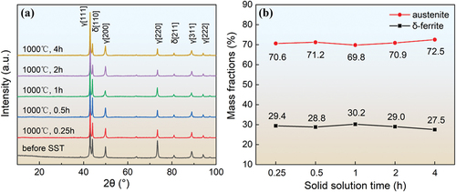
displays XRD diffraction patterns of the microstructure of Fe-Mn-Al dual-phase HR and SST for different durations. It can be observed that after various solid solution treatments, both austenite (γ) diffraction peaks and δ-ferrite (δ) diffraction peaks are evident in the experimental steel. The strongest peak for austenite corresponds to the γ[111], while the strongest peak for δ-ferrite is δ[110]. With increasing solid solution time, the peak intensity of δ-ferrite initially slightly increases and then decreases. Based on the peak intensity of the highest diffraction peaks for the two-phase microstructure in and their corresponding K factors, the mass fractions of γ and δ-ferrite in the experimental steel after different solid solution treatments were calculated using the ‘adiabatic method [Citation24], ’ as shown in . At 1000°C, as the solid solution time increases, the volume fractions of δ-ferrite initially increase slightly and then decrease, but the changes are not very significant.
Figure 2. (a) XRD patterns of the experimental steel HR and after different durations of solid solution treatment (γ: austenite, δ: δ-ferrite) and (b) the changes in mass fractions of each phase with solid solution time.
Grain size and grain boundary angles
To further characterize the microstructural features of the SST samples, the EBSD microstructure and grain boundary angle analysis of the experimental steel at 1000°C at various times are shown in . In the figure, red represents austenite (face-centred cubic: FCC), blue represents δ-ferrite (body-centred cubic: BCC), thick black solid lines represent high-angle boundaries (HAGBs, >15°), thin white solid lines represent low-angle boundaries (LAGBs, 2 ~ 15°), and thick yellow solid lines represent Σ3 special lattice boundaries (Σ3-CSL, 60°). RD and ND respectively denote the rolling direction and the plate thickness direction. Studies have shown that [Citation25], annealed twins in austenite, formed after hot rolling or heat treatment, are variants formed by a 60° rotation along the {111} plane normal. Annealed twins are generally considered low-Σ value coincident site lattice grain boundaries and belong to the Σ3 special grain boundary category. Therefore, the EBSD Σ3-CSL grain boundaries in correspond to austenite annealed twin boundaries. From the figure, it can be observed that aside from changes in microstructure and phase proportions, the microstructural alterations of the SST samples also include the straightening of HAGBs, a reduction in the number of LAGBs, an increase in the number of annealed twin boundaries, and an enlargement of grain size. These characteristics of microstructural changes indicate that the experimental steel underwent significant static recrystallization during the solid solution treatment process.
Figure 3. EBSD microstructure and grain boundary angle analysis of the experimental steel after solid solution treatment at 1000°C for different durations: (a) 15 minutes, (b) 60 minutes, (c) 240 minutes, and (d) changes in the average grain size of austenite and δ-ferrite, as well as the proportion of grain boundaries, concerning solid solution time.
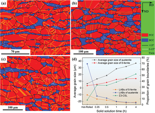
Based on the EBSD analysis results, the changes in the average grain size of austenite and δ-ferrite, as well as the percentage of LAGBs and Σ3-CSL grain boundaries concerning solid solution time, are shown in . It can be observed that with increasing solid solution time, both the average grain size of austenite and δ-ferrite gradually increase, but at different rates. Additionally, the formation of annealed twins during the solid solution treatment is caused by the migration of austenite grain boundaries, so the percentage of Σ3-CSL grain boundaries (annealed twin boundaries) exhibits a similar trend to that of the austenite grain size.
Elemental distribution and microhardness
To quantitatively describe the differences in the two-phase microstructure of austenite and δ-ferrite after solid solution treatment, elemental distribution, and microhardness were measured using EDS and a nanomechanical probe, respectively. The results are shown in . displays the variations in Mn and Al content in both austenite and δ-ferrite with different solid solution times. It can be observed that after solid solution treatment, the alloy elements still exhibit non-uniform distribution in the two-phase microstructure, with Mn and Al concentrating in austenite and δ-ferrite, respectively. With increasing solid solution time, the distribution of these alloy elements remains similar to the HR state and does not show significant changes. It is noted that the elemental distribution during solid solution primarily results from changes in phase proportions. This distribution can have an impact on the microhardness of the two-phase microstructure, austenite stacking fault energy, and deformation mechanisms. According to , the variation in microhardness of austenite and δ-ferrite concerning solid solution time is depicted in . It can be observed that with increasing solid solution time, the microhardness of austenite continuously decreases. Solid solution treatment reduces the hardness of δ-ferrite. However, with extended solid solution time, the microhardness of δ-ferrite does not show significant changes. Studies have indicated that the microhardness of both ferrite and austenite is influenced by factors such as chemical composition, grain shape, phase continuity, and internal stresses. The higher hardness of ferrite may be related to the formation of DO3-ordered intermediate phases [Citation26]. For the experimental steel in this study, the decrease in microhardness of austenite is attributed to the softening effect caused by the occurrence of static recrystallization during solid solution. On the other hand, δ-ferrite belongs to high-temperature stable phases, so its microhardness is relatively higher than that of austenite. When the solid solution temperature is elevated (e.g. 1000°C), the solid solution strengthening caused by a substantial amount of Mn elements makes the microhardness of δ-ferrite stabilize and not significantly influenced by solid solution time.
Figure 4. (a) elemental distribution and (b) microhardness in austenite and δ-ferrite as a function of solid solution time.
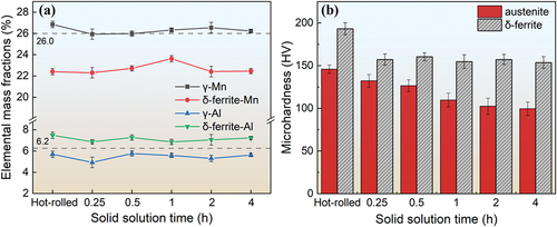
Table 1. Fe-Mn-al dual-phase elemental distribution and microhardness in the two-phase microstructure before and after various solid solution treatments.
Mechanical performance
After different durations of solid solution treatment, the comprehensive mechanical properties of Fe-Mn-Al dual-phase are presented in ((longitudinal cross-section (LCS) and transversal cross-section (TCS)). According to , the trend of strength (LCS) in the experimental steel as a function of solid solution time is plotted in . It can be observed that at a solid solution temperature of 1000°C, with increasing solid solution time, both the tensile strength (σt) and yield strength (σy) of the experimental steel continuously decrease. As the solid solution time increases from 0.25 hours to 4 hours, the tensile strength of the steel decreases from 579.1 MPa to 553.2 MPa, and the yield strength decreases from 376.4 MPa to 332.2 MPa.
Figure 5. The variation of (a) tensile strength and yield strength, (b) ETF and PSE, and (c) impact toughness at 25°C as a function of solid solution time in Fe-Mn-al dual-phase.
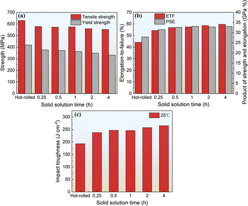
Table 2. Mechanical properties of Fe-Mn-al dual-phase before and after various solid solution treatments.
The trend of elongation-to-failure (ETF) and product of strength and elongation (PSE) in the experimental steel concerning solid solution time is shown in . It can be observed that the ETF exhibits an inverse trend to strength. After increasing the solid solution time from 0.25 hours to 4 hours, the ETF increases from 54.4% to 59.7%. However, due to the decrease in tensile strength, the PSE initially increases and then decreases with extended solid solution time, reaching its maximum value at 1 hour. The variation in impact toughness of the experimental steel at room temperature (25°C) concerning solid solution time is shown in . It can be observed that the impact toughness of the experimental steel follows the same trend as its ductility. After 4 hours of solid solution time, the impact toughness reaches 265.2 J⋅cm−2 at room temperature. Furthermore, as shown in , after solution at 1000°C for 1 hour, the anisotropy of the mechanical properties disappears, and the longitudinal and transverse mechanical properties of the steel are equivalent.
Plastic deformation mechanisms of Fe-Mn-al dual-phase steel
The mechanical performance experiments in section 3 demonstrate that δ-ferrite plays a role in strengthening as the second phase in Fe-Mn-Al dual-phase steel [Citation27]. However, the microhardness of δ-ferrite at room temperature is significantly higher than that of austenite, leading to inevitable deformation incompatibilities between the two-phase structures. Additionally, due to the higher dislocation energy of δ-ferrite, cross-slip of dislocations usually occurs during deformation. In contrast, austenite has lower dislocation energy, and plastic deformation primarily occurs through a planar slip or deformation-induced twinning. Currently, research on the deformation mechanisms of Fe-Mn-Al lightweight steel has mainly focused on theories such as Shear-Induced Plasticity (SIP) and Microband-Induced Plasticity (MBIP) dominated by dislocation slip. There is a lack of research regarding the interaction between deformation twinning and dislocations, as well as their impact on the mechanical properties of Fe-Mn-Al dual-phase steel. Thus, the 1000°C SST for 1 hour Fe-Mn-Al dual-phase steel with the best comprehensive mechanical properties was selected as the subject of our mechanical behaviour study. Through room temperature pre-strain tensile tests with different deformation levels of 1.0 mm, 3.0 mm, 6.0 mm, 9.0 mm, and the ultimate rupture point (12.9 mm), and various metallographic analysis methods such as XRD, SEM, EBSD, and TEM, we observed the microstructure, grain boundary angles, and dislocation structures of the experimental steel. Our aim was to uncover the deformation mechanisms and coordination relationships between austenite and δ-ferrite at various deformation stages. Ultimately, we sought to clarify the intrinsic connection between the work-hardening behaviour and structural evolution of the experimental steel during plastic deformation.
Microstructure evolution during deformation
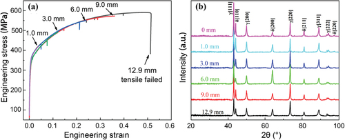
The engineering stress-strain curves under different deformation levels are shown in . Based on the complete tensile strain-stress curve in , the experimental steel tensile strength and yield strength were measured as 591.2 MPa and 377.3 MPa, respectively, with a uniform elongation of 52.4%. These values are consistent with the results in . Since the fracture location of the samples occurred at the boundary of the gauge length region (deformation zone), the measured elongation of the experimental steel was slightly lower than the true value (57.6%). The XRD patterns of the microstructure of the experimental steel under different deformation levels are shown in . It can be observed that under different deformation levels, only γ diffraction peaks and δ diffraction peaks are present in the microstructure, and the peak intensities do not show significant changes with increasing deformation. This indicates that austenite exhibits high thermal stability and mechanical stability at room temperature, and no phase transformation occurs during deformation. The deformed microstructure consistently consists of both austenite and δ-ferrite phases.
Figure 6. (a) engineering stress-strain curves under different deformation levels. (b) XRD patterns of microstructures under different deformation levels (γ: austenite, δ: δ-ferrite).
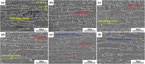
The SEM microstructures of Fe-Mn-Al dual-phase steel stretched to different levels of deformation are shown in . In the figure, RD represents the rolling direction, which is also the direction of tensile deformation, and ND represents the plate thickness direction. From , it can be observed that after 1 hour of solid solution treatment at 1000°C, the room temperature microstructure of the experimental steel consists primarily of ‘island-like’ δ-ferrite grains and equiaxed recrystallized austenite grains. Within the austenite grains, there are coarse annealing twins (yellow arrows). At a deformation level of 1.0 mm (), some slip bands (red arrows) begin to appear within the austenite grains. As the deformation level increases from 1.0 mm to 6.0 mm (), the slip bands gradually increase in number and density. Simultaneously, the original equiaxed grains elongate along the deformation direction, and the annealing twin boundaries within the austenite grains become gradually less distinct, with a reduction in the number of annealing twins. At a deformation level of 9.0 mm (), the δ-ferrite grains elongate into ‘stripes’, fine deformation twins (blue arrows) start to appear within the austenite grains, and the number of annealing twins becomes extremely limited. In addition, small pores (red circles) appear at the austenite/δ-ferrite grain boundaries and within the austenite grains. These pores will serve as crack initiation sites during the later stages of deformation. When the deformation level reaches 12.9 mm (), the specimen fractures. At this point, the deformation twins within the austenite increase significantly and become finer, and the annealing twins completely disappear.
Figure 7. SEM microstructures of Fe-Mn-al dual-phase steel at different levels of deformation: (a) un-deformed; (b) 1.0 mm; (c) 3.0 mm; (d) 6.0 mm; (e) 9.0 mm; (f) 12.9 mm (failed).
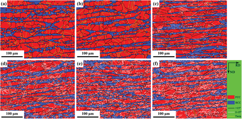
shows the EBSD microstructure and grain boundary angle analysis of the experimental steel at different deformation levels. The labelling is consistent with . Studies [Citation28] have shown that there is a corresponding relationship between defects and grain boundary angles. When the grain boundary angles are 0 ~ 3°, 3 ~ 15°, 15 ~ 60°, and 60°, the corresponding defects are dislocations, sub-grain boundaries, grain boundaries and phase boundaries, and twin boundaries (including annealing twin boundaries and deformation twin boundaries), respectively. Since sub-grain boundaries are typically caused by dislocation motion during deformation, we use the 2 ~ 15° LAGBs as a semi-quantitative characterization of the dislocation density in the deformed microstructure. As analysed in section 3, a large number of Σ3 special lattice boundaries in the austenite before deformation are annealing twin boundaries formed during the solid solution treatment process. These twin boundaries are the result of the migration of HAGBs during austenite static recrystallization. From , it can be seen that before tensile deformation, the defects in the experimental steel mainly include HAGBs and annealing twin boundaries in the austenite, with a small number of LAGBs concentrated in the δ-ferrite. With the increase in deformation, the number of LAGBs in both the austenite and δ-ferrite gradually increases, and the two-phase microstructure becomes ‘striped’ along the tensile direction. This indicates that a large number of dislocation structures have formed within the grains of both the austenite and δ-ferrite during the deformation process. At the same time, with increasing deformation, the annealing twin boundaries in the austenite gradually decrease, indicating that annealing twins also participate in plastic deformation.
Figure 8. EBSD maps of Fe-Mn-al dual-phase steel at different levels of deformation: (a) un-deformed; (b) 1.0 mm; (c) 3.0 mm; (d) 6.0 mm; (e) 9.0 mm; (f) 12.9 mm (failed).
To quantitatively characterize the microstructural evolution of the experimental steel during tensile deformation, the distribution of grain boundary angles was statistically analysed based on EBSD results at different deformation levels, as shown in . The relationship between the distribution frequencies of different grain boundaries concerning deformation levels and the distribution of LAGBs in austenite and δ-ferrite is presented in . Combining the information from , the microstructural evolution during the tensile deformation process can be divided into three phases.
Figure 9. Grain boundary angle distribution of Fe-Mn-al dual-phase steel at different levels of deformation: (a) un-deformed; (b) 1.0 mm; (c) 3.0 mm; (d) 6.0 mm; (e) 9.0 mm; (f) 12.9 mm (failed); (g) relationship between the distribution frequencies of different grain boundaries and the deformation levels; (h) distribution of low-angle boundaries (LAGBs) in austenite and δ-ferrite; (i) microhardness variation of austenite and δ-ferrite with different deformation levels.
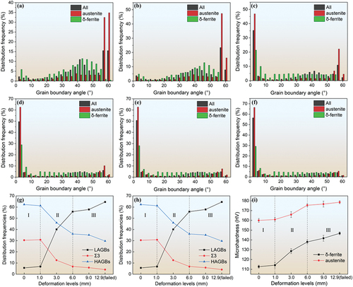
Phase I: before the tensile deformation, the experimental steel contained 62.9% HAGBs, 30.8% annealing twin boundaries (Σ3), and 6.3% LAGBs, which is consistent with the results in . It is worth noting that before plastic deformation, the LAGBs content in the austenite was only 2.4%, while in the δ-ferrite, it was 9.9%. This difference is due to the incomplete static recrystallization of δ-ferrite during the solid solution treatment and the additional thermal stresses between the two-phase structures during water cooling (further analysis is detailed in the following text). At a deformation level of 1.0 mm, there was no significant change in the distribution of grain boundary angles in the microstructure compared to the pre-deformation state. Only the LAGBs content in the austenite increased from 2.4% to 4.2% during this stage, indicating that a large-scale proliferation of dislocations did not occur in this phase.
Phase II: as the deformation increases from 1.0 mm to 6.0 mm, the LAGBs content in the experimental steel increases from 7.3% to 56.3%, while the HAGBs and Σ3 content decrease from 61.6% and 31.1% to 36.4% and 7.3% respectively. This indicates that in this stage, there is intense mutual movement and substantial accumulation of dislocations. A large number of annealing twins gradually disappear during the plastic deformation process, and the decrease in HAGBs content is a relative result of the increase in LAGBs. Additionally, LAGBs content increases more rapidly in the austenite phase (LAGBs-γ) compared to the δ-ferrite phase (LAGBs-δ). This suggests that the austenite phase undergoes more intense dislocation movement and accumulates dislocations at a faster rate, indicating that it primarily bears the deformation [Citation27,Citation29,Citation30].
Phase III: As the deformation increases from 6.0 mm to 12.9 mm (failed), the content of LAGBs in both austenite and δ-ferrite slowly increases, resulting in a plateau. This indicates that after intense plastic deformation, the dislocation density in the two-phase structure reaches a saturation point. At this point, a large number of dislocations are hindered due to complex mutual motion, leading to local stress concentration. With the continuous increase in local stress, fine deformation twins finally form in the austenite, and the number of deformation twins increases with the increasing deformation, as shown in . However, according to , the content of Σ3 grain boundaries in this stage gradually decreases with increasing deformation. This is because the EBSD analysis uses a scanning step size of 0.5 μm, which means that only deformation twins larger than 500 nm can be identified as Σ3 grain boundaries. Although deformation twins, like annealing twins, have a Σ3 special lattice relationship with the austenite matrix, deformation twins are smaller in size and are generally difficult to identify by EBSD. Therefore, the evolution of deformation twins cannot be reflected by the change in Σ3 grain boundary content and can only be further analysed through TEM morphology.
To understand the work-hardening behaviour of the experimental steel at different deformation stages, microhardness measurements of the austenite and δ-ferrite were conducted using a nanoindentation probe, as shown in . From the graph, it can be observed that before tensile deformation, the Vickers hardness (HV) values of austenite and δ-ferrite were 112.7 and 160.6, respectively, which are consistent with the results in . At a deformation level of 1.0 mm (Phase I), there was not much change in the HV values of the two-phase structure. As the deformation increased from 1.0 mm to 6.0 mm (Phase II), the HV values in the austenite and δ-ferrite increased from 114.5 and 161.5 to 138.2 and 175.7, respectively, with the hardness of the austenite increasing significantly more than that of the δ-ferrite. This aligns with the pattern observed in , where the content of LAGBs in both the austenite and δ-ferrite follows a similar trend. This further suggests that in the early stages of plastic deformation, the austenite primarily bears the deformation, resulting in a greater work-hardening capacity relative to the δ-ferrite. After the deformation exceeds 6.0 mm (Phase III), the HV value of δ-ferrite slowly increases and gradually reaches an approximate equilibrium state, while the HV value of austenite continuously increases from 138.2 to 146.7. As shown in , it can be observed that in the later stages of plastic deformation, both LAGBs (dislocation density) in austenite and δ-ferrite reach an equilibrium value. Therefore, the increase in the microhardness of austenite mainly results from the work-hardening effect generated by deformation twinning.
Dislocation structure transformation during deformation
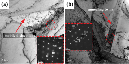
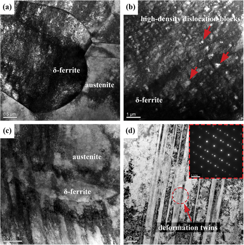
The TEM microstructure of the experimental steel after 1 hour of solid solution treatment at 1000°C is shown in . From , it can be observed that there is already a small number of mobile dislocations within the δ-ferrite grains before tensile deformation. This is because the austenite phase, compared to the δ-ferrite, has a larger thermal expansion coefficient and a smaller volume ratio. During the rapid quenching process in water after solid solution annealing, the austenite grains undergo significant volume contraction, causing additional tensile stress on the adjacent δ-ferrite grains, resulting in the generation of mobile dislocations within the δ-ferrite grains [Citation31]. This result is consistent with the higher content of LAGBs within the δ-ferrite grains shown in (Phase I). Additionally, the electron diffraction pattern of the δ-ferrite in exhibits the characteristic [] zone axis of the BCC structure. shows the annealing twin morphology and electron diffraction pattern in the austenite phase.
Figure 10. TEM morphology of steel microstructure before tensile deformation experiments (a) mobile dislocations in δ-ferrite; (b) annealing twins in austenite.
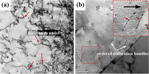
When the deformation is 1.0 mm (4%), a significant number of dislocation nodes appear in the δ-ferrite phase, as shown in . This is a typical characteristic of single-system cross-slip in BCC crystals. Due to the δ-ferrite having multiple slip systems (48 in total) and a high stacking fault energy, during the early stages of plastic deformation when the dislocation density is low, dislocations exhibit good three-dimensional mobility. In other words, certain favourably oriented dislocations easily undergo cross-slip between different slip planes. As the dislocation density increases, dislocations intersect and form dislocation nodes. These dislocation nodes lead to work hardening of the steel through the pinning effect on dislocation motion. As seen in , a large number of uniformly distributed ordered dislocation bundles form within the austenite grain. These dislocation bundles move independently from the interior of the grain towards the grain boundaries. This is a characteristic of planar slip observed in low-stacking fault energy metals during the early stages of plastic deformation. In the enlarged portion in the upper right corner of , numerous drag particles (red arrows) are uniformly distributed on the dislocation bundles and the direction of drag points opposite to the direction of dislocation slip (black arrows). According to the theory of Kock et al. [Citation31], these drag particles are caused by the pinning effect of solute elements in the austenite on dislocation motion.
Figure 11. TEM morphology at a deformation level of 1.0mm (a) dislocation nodes in δ-ferrite; (b) ordered dislocation bundles in austenite.
When the deformation reaches 3.0 mm (12%), both the austenite and δ-ferrite phases exhibit a significantly increased dislocation density, as shown in . The dislocation structure in the δ-ferrite becomes complex and difficult to distinguish due to dislocation entanglement and distortion (). Such dislocation structures often occur in BCC crystals with high stacking fault energy and result from dislocations simultaneously operating in multiple slip systems and intersecting with each other. In comparison to the δ-ferrite, the increase in dislocation density in the austenite phase is more pronounced, and it exhibits a series of complex planar slip features, including extended dislocations, dislocation networks, and face-angle dislocations (Lomer-Cottrell dislocations), as shown in . Additionally, a high-density dislocation structure is observed in the annealed twin boundaries of the austenite (), indicating that plastic deformation has begun in the annealed twin boundaries at this stage.
Figure 12. TEM morphology at a deformation level of 3.0mm: (a) dislocation entanglement in δ-ferrite. (b) extended dislocations in austenite. (c) dislocation network. (d) face-angle dislocations. (e) high-density dislocations in annealing twins. (f) diffraction pattern of annealing twins in (e).
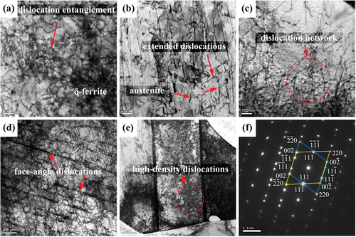
In FCC crystals with lower stacking fault energy, full dislocations on {111} close-packed planes tend to decompose into two Shockley partial dislocations. This decomposition reduces the energy required for the full dislocation to glide on the {111} plane. However, it also leads to the formation of a stacking fault between the two partial dislocations. This type of dislocation structure, consisting of one full dislocation, two partial dislocations, and a stacking fault region in between, is commonly referred to as an extended dislocation, as indicated by the red arrows in . Because the two partial dislocations in the extended dislocation are on the same slip plane with the same sign, their Burgers vectors are oriented at a 60° angle, resulting in a natural repulsion between them. When the stacking fault energy is low, it becomes difficult for these partial dislocations to gather and form a complete screw dislocation, which would enable cross-slip. Therefore, extended dislocations can only move on their respective slip planes, exhibiting planar slip characteristics [Citation32–37].
Dislocation networks and face-angle dislocations are the result of two or more co-planar slip systems sliding within the same grain in a FCC crystal. illustrates the formation process of a dislocation network. When a group of dislocations with Burgers vector b1 on the (111) plane intersects with a screw dislocation b2 on the () plane, and the angle between the Burgers vectors of these two dislocations is 120°, they attract each other and undergo dislocation reactions to generate a new dislocation b3. Due to the effects of line tension, in equilibrium, the dislocation lines eventually form a polygonal dislocation network, as shown in . This type of dislocation network is often observed in the early stages of plastic deformation in FCC crystals and can enhance the work-hardening capability of steel by hindering dislocation slip on the slip planes. Face-angle dislocations are fixed dislocations in FCC crystals, and their formation process is illustrated in . On the (111) and (
) planes, full dislocations a/2[
] and a/2[011], respectively, decompose into two Shockley partial dislocations:
Figure 13. Formation process schematic of (a) dislocation network (b) face-angle dislocation in austenite.
When two extended dislocations move in opposite directions on their respective slip planes, new pure-edge-type partial dislocations are generated when one of the partial dislocations within each extended dislocation reaches the intersection line between the two slip planes:
This new partial dislocation, located on the (001) slip plane, cannot undergo slip and is considered a fixed dislocation. There is a stacking fault region between the fixed dislocation a/6[110] and the other two partial dislocations a/6[] and a/6[112]. This configuration of dislocations, formed at the angle between two {111} planes and consisting of three partial dislocations and two stacking fault regions, is referred to as a face-angle dislocation. shows the TEM morphology of the fixed dislocation within the face-angle dislocation on a specific interface. Since this fixed dislocation can simultaneously inhibit slip on both {111} planes, face-angle dislocations exhibit better work-hardening capabilities compared to dislocation networks.
At a deformation level of 6.0 mm (24%), the dislocation density in the δ-ferrite phase increases further, forming numerous dislocation cell structures, as shown in . These dislocation cells typically consist of sub-grain boundaries with angles ranging from 3 to 15°, strongly impeding dislocation motion. In the austenite phase, the dislocation structure appears as non-coplanar dislocation bundles from different slip systems intersecting, forming a Taylor lattice, as depicted in . Measurements indicate that the spacing between dislocation bundles of the same slip system is approximately 400 nm. The Taylor lattice, as a low-energy dislocation structure, typically appears in the mid-stage of plastic deformation in FCC crystals. It not only hinders dislocation motion but also enhances work hardening by refining the austenite grain size. Simultaneously, a large area of high-density dislocation walls (HDDWs) forms near the austenite/δ-ferrite phase boundary within the austenite grain, as shown in . It is believed that the formation of HDDWs results from the accumulation of a large number of dislocation networks at the austenite/δ-ferrite phase boundary within the austenite grain, as proposed by Wand et al. [Citation38]. Due to the strain incompatibility between austenite and δ-ferrite, during the later stages of plastic deformation, dislocation pile-ups easily occur at the austenite/δ-ferrite phase boundary, causing stress concentration and transferring strain from the austenite to the δ-ferrite. This local high-density dislocation structure strongly impedes dislocation motion, promotes coordinated deformation between austenite and δ-ferrite, and reflects the second phase strengthening role of δ-ferrite in Fe-Mn-Al dual-phase steel. Furthermore, illustrates the process in which annealing twins in the austenite are gradually consumed or ‘swallowed up’ by dislocation motion, causing the reduction of annealed twin boundaries with increasing deformation, as shown in . Li et al. [Citation39], using first-principles calculations from an atomic-level perspective, studied the disappearance process of annealed twins during plastic deformation. They found that annealed twin boundaries can gradually migrate during the deformation process, and the larger the annealed twin, the faster the migration of the grain boundaries. According to dislocation theory, at a certain temperature, twin boundary dislocations undergo slip, climb, and interactions, eventually annihilating. As twin boundary dislocations move, the twinning relationship at these boundaries gradually disappears, leading to the ultimate disappearance of annealed twins.
Figure 14. TEM morphology at a deformation level of 6.0mm: (a) dislocation cells in δ-ferrite; (b) Taylor lattice in austenite; (c) high-density dislocation walls at the austenite/δ-ferrite phase boundary; (d) disappearance of annealing twin boundaries. TEM morphology at a deformation level of 9.0mm: (e) high-density dislocation blocks in δ-ferrite; (f) microbands in austenite; (g) microbands crossing annealing twin boundaries; (h) deformation twins in austenite.
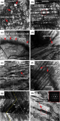
At a deformation level of 9.0 mm (36%), the dislocation cells in the δ-ferrite phase evolve into high-density dislocation blocks, as shown in . This stable dislocation structure is often observed in the later stages of plastic deformation in BCC crystals. During this stage, dislocation motion is strongly impeded, and there are only a few active slip systems within the grains, leading to the accumulation of immobile dislocations and stress concentration. In the austenite phase, the dislocation structure evolves into a parallel distribution of microbands with spacing approximately between 0.5 to 1 μm, as depicted in . These microband structures consist of pairs of high-density immobile dislocation rows and are commonly observed in the late stages of plastic deformation in FCC crystals, causing stress concentration. As seen in , the microband structures deviate by approximately 60° after passing through the annealed twins and then continue to distribute within the austenite grains in the same extension direction. This is because both sides of the annealed twins have the same crystal orientation. Research has shown that only dislocations with a unique slip direction can cross twin boundaries, indicating that dislocation motion is heavily suppressed during this deformation stage, leading to severe stress concentration within the austenite grains. Additionally, the presence of numerous microbands crossing through the annealed twins can change their orientation and lead to their disappearance, resulting in additional work hardening.
As observed in , deformation twins containing high-density dislocations appear within the austenite grains, with a thickness of approximately 100 nm. This indicates the occurrence of deformation-induced twinning in the austenite at this stage. Twinning, as another important form of plastic deformation in FCC metals, requires a much higher critical shear stress compared to dislocation slip. Therefore, deformation twins often occur in regions of stress concentration where dislocation motion is hindered. Tewary et al. [Citation40] have shown that the critical stress required for the formation of deformation twins in the austenite is related to grain size and stacking fault energy. As stacking fault energy increases within the range of 25 to 55 mJ⋅m−2, the critical stress required for deformation twins also increases. According to our previous work [Citation41], after the experimental steel is solutionized at 1000°C for 1 hour, the actual stacking fault energy of the austenite is 52.8 mJ⋅m−2. This means that the Twinning-Induced Plasticity (TWIP) mechanism in the experimental steel can only occur in the later stages of plastic deformation when stress concentration is significant. Cohen and Weertman [Citation42] found that the nucleation of deformation twins in the austenite originates from the stacking fault in the face-angle dislocation of the Taylor lattice. With increasing deformation, the interaction of multiple slip systems leads to local stress concentration, causing the stacking fault to gradually evolve into deformation twins under higher shear stresses. Therefore, the presence of stacking faults generated by the slip of Shockley partial dislocations within face-angle dislocations, as well as the stress concentration caused by features like Taylor lattices and microbands, are two necessary conditions for the formation of deformation twins in the austenite. In other words, the formation of deformation twins in the austenite is the result of the combined effects of Shockley partial dislocation slip and stress concentration.
When the deformation level reaches 12.9 mm (51.6%), the specimen fractures, and at this point, the dislocation structure in the δ-ferrite phase is almost entirely composed of high-density dislocation blocks, as shown in . This indicates that the dislocation density has reached saturation, which is consistent with the EBSD analysis results in . In the austenite phase, microbands with different orientations intersect, forming many low-density dislocation regions, as indicated by the red arrows in . These low-density dislocation regions are prone to stress concentration in the later stages of deformation, which can lead to the formation of macroscopic voids within the austenite grains, as shown in , ultimately contributing to specimen fracture. As seen in , the microbands in the austenite phase traverse through the δ-ferrite phase in the same direction, indicating that at this point, coordinated deformation has occurred between the austenite and δ-ferrite phases. shows that the number of deformation twins in the austenite phase has significantly increased compared to , indicating that the TWIP mechanism plays an important role in work hardening in the later stages of plastic deformation in the experimental steel.
Figure 15. TEM morphology at a deformation level of 12.9 mm: (a) high-density dislocation blocks in δ-ferrite. (b) microband junctions in austenite. (c) microbands passing through δ-ferrite grains. (d) deformation twins in austenite.
In summary, during the plastic deformation process, the δ-ferrite phase exhibits a series of characteristics related to cross-slip, and its dislocation microstructure evolution process can be described as follows: mobile free dislocations → dislocation nodes → dislocation entanglement and twisting→ dislocation cells → high-density dislocation blocks. In the early stages of plastic deformation, the austenite phase exhibits typical planar slip characteristics. In the later stages of plastic deformation, the deformation mechanism in the austenite phase is primarily dominated by TWIP. The microstructure evolution process in the austenite phase can be summarized as follows: dislocation bundle formation → series of planar slip features (extension dislocations, dislocation network, and face-angle dislocations) → Taylor lattice + high-density dislocation walls → microbands + deformation twins.
Strength-ductility mechanism
During plastic deformation, engineering stress-engineering strain and true stress-true strain can be converted between each other using Equationequations (4)(4)
(4) and (Equation5
(5)
(5) ) [Citation43]:
In the equations, σ and ε represent true stress and true strain, while and
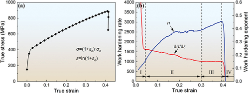
represent engineering stress and engineering strain, respectively. Based on the engineering stress-strain curve shown in , the true stress-strain curve can be derived as shown in . From the graph, it is evident that the true stress gradually increases with increasing true strain, indicating continuous work hardening behaviour during the tensile deformation of the experimental steel. To quantitatively characterize the work hardening capacity of the experimental steel, the relationship between true stress and true strain is expressed using the Ludwik-Hollomon equation [Citation44]:
Figure 16. (a) tensile true stress-strain curve. (b) relationship between strain and work hardening rate, as well as work hardening exponent, of Fe-Mn-al dual-phase steel.
In the equation, K represents the material constant, and n is the strain hardening exponent. The value of n indicates the material ability to undergo uniform deformation through strain hardening before necking occurs. By taking the derivative of Equationequation (6)(6)
(6) with respect to both sides, we can obtain:
In the equation, dσ/dε represents the work hardening capacity. By substituting Equationequation (6)(6)
(6) into Equationequation (7)
(7)
(7) , we can obtain:
Finally, based on Equationequation (8)(8)
(8) , the relationship between the strain hardening rate (dσ/dε) and the strain hardening exponent (n) of the experimental steel with respect to true strain can be obtained, as shown in . From the graph, it can be observed that the tensile deformation process of Fe-Mn-Al dual-phase steel can be divided into four stages. Stage I: the strain hardening rate (dσ/dε) sharply decreases with increasing true strain, while the strain hardening exponent (n) linearly increases. This indicates a rapid decrease in work hardening, and the material exhibits linear strain hardening. Stage II: as true strain continues to increase, the strain hardening rate (dσ/dε) decreases slowly, indicating sustained work hardening. The strain hardening exponent (n) continues to increase, but the rate of increase is significantly slower than in Stage I. Stage III: with further increases in true strain, the strain hardening rate (dσ/dε) reaches a plateau, and the strain hardening exponent (n) increases rapidly. This stage exhibits the typical work-hardening behaviour commonly seen in TWIP steel. Stage IV: in this final stage, both the strain hardening rate and the strain hardening exponent decrease rapidly, indicating that the material has entered an unstable state.
Considering the microstructural evolution and changes in dislocation structures during the deformation process, the work-hardening behaviour of the experimental steel in different deformation stages is primarily determined by the interactions among dislocations, deformation twins, and grain boundaries. We can summarize:
Corresponding to Phase I in , the stress level is relatively low, and both the austenite and δ-ferrite deformation mechanisms are dominated by a single dislocation slip. In austenite, due to its lower stacking fault energy, extended dislocations with larger widths are formed, making it difficult for cross-slip to occur, resulting in significant planar slip characteristics (dislocation bunching). In δ-ferrite, with higher stacking fault energy, dislocations undergo cross-slip, forming numerous dislocation nodes. At this stage, the overall dislocation density is relatively low, and the dislocation increment is slow. Work hardening mainly comes from dislocation interactions in δ-ferrite. Therefore, the work hardening rate decreases rapidly with increasing true strain at this stage. Since dislocations are highly mobile in this stage, the material exhibits good uniform deformation capability, leading to a rapid increase in the work hardening index with increasing true strain.
Corresponding to Phase II in , as deformation progresses, mobile dislocations are hindered at certain obstacles, such as grain boundaries, dislocation nodes, or annealing twins. This causes stress concentration, leading to increased local stress and the initiation of multiple slip systems in both the austenite and δ-ferrite. With increasing deformation, dislocations rapidly accumulate, resulting in the formation of a series of complex planar slip features in austenite (extended dislocations, dislocation network, face angle dislocations, Taylor lattices) and typical wave-like slip features in δ-ferrite, such as dislocation entanglement and dislocation cells. These dislocation structures strongly impede dislocation motion, enhancing the work-hardening capability of the steel. As a result, the work hardening rate gradually decreases with increasing true strain. However, the obstruction of dislocation movement also leads to local stress concentration, reducing the ability of material for uniform deformation and slowing the growth rate of the work hardening index.
Due to the larger atomic plane spacing {111} and lower lattice resistance in the austenite compared to δ-ferrite, dislocation motion requires relatively less energy. Therefore, in the early stages of plastic deformation, austenite primarily bears the deformation, resulting in faster growth of dislocation density and microhardness in the austenite compared to δ-ferrite. As deformation progresses, high-density dislocation walls form at the austenite/δ-ferrite phase boundaries, causing stress concentration and gradually transferring strain from austenite to δ-ferrite. This also leads to additional work-hardening effects. Therefore, in Phase II, work hardening is primarily attributed to the suppression of dislocation motion by the high-density dislocation structures generated from multi-system slip and the second phase strengthening effect of the hard δ-ferrite. Additionally, the interaction between annealing twins and dislocation motion contributes to work hardening.
(3) Corresponding to Phase III in , at this point, both austenite and δ-ferrite have undergone coordinated deformation. There are fewer active slip systems in both phases, making dislocation motion difficult. Dislocation density reaches a saturated state, with δ-ferrite exhibiting a stable high-density dislocation block structure. Austenite contains immobile microbands and their interactions. As strain continues to increase, stress concentration from dislocation structures like Taylor lattices and microbands in austenite also increases. When the stress reaches the critical value required for twinning, localized twinning occurs in austenite. With increasing deformation, the number of deformation twins gradually increases. Deformation twins, like HAGBs, hinder dislocation motion. Therefore, the generation of deformation twins shortens the average free path of dislocation motion through the dynamic Hall-Petch effect, thus enhancing the work-hardening capability of the steel. This results in a plateau in the work hardening rate with increasing true strain. Additionally, the formation of deformation twins can release stress concentration caused by dislocation pile-ups, allowing deformation to spread to areas with lower stress. This improves the ability of steel to deform uniformly, leading to a rapid increase in the work hardening index with increasing true strain. Therefore, in Phase III, the primary source of work-hardening behaviour is the TWIP effect induced by deformation twinning in austenite.
(4) The formation of deformation twins cannot release the continuously increasing stress. High-density dislocation blocks in δ-ferrite and microbands in austenite generate strong stress concentrations. This prevents further uniform plastic deformation, leading to a sharp decrease in both the work hardening rate and the work hardening index. Ultimately, numerous microvoids form in low-density dislocation regions at austenite/δ-ferrite phase boundaries and at microband intersections, as shown in . These microvoids gradually coalesce and grow into crack initiation sites, causing necking and fracture in the specimen.
Conclusions
The microstructure of Fe-Mn-Al dual-phase steel remains composed of austenite and δ-ferrite in different deformation stages, indicating that austenite exhibits relatively high thermal stability and mechanical stability at room temperature.
Due to the larger atomic spacing on the close-packed planes {111} in austenite compared to δ-ferrite, the energy required for dislocation slip in austenite is relatively lower. Consequently, in the early stages of plastic deformation, austenite bears the main deformation, leading to a relatively faster increase in dislocation density and microhardness in austenite. In the later stages of plastic deformation, strain is transferred from austenite to δ-ferrite through high-density dislocation walls, resulting in coordinated deformation of the two-phase structure.
During plastic deformation, δ-ferrite exhibits a series of cross-slip characteristics, with a microstructural evolution of dislocations from mobile free dislocations to dislocation nodes, entanglement, twinning, and the formation of high-density dislocation blocks. In the early stages of plastic deformation, austenite exhibits typical planar slip characteristics. In the later stages of plastic deformation, the primary deformation mechanism in austenite becomes TWIP, with a microstructural evolution from dislocation bundling to a series of planar slip features (expanded dislocations, dislocation network, and twin boundaries), Taylor lattices, high-density dislocation walls, microbands, and deformation twins.
When the strain is less than 36%, both austenite and δ-ferrite primarily deform through dislocation slip. However, when the strain exceeds 36%, deformation twins begin to form in austenite, and their density increases with increasing strain. The formation of deformation twins in austenite is facilitated by the cross-slip of Shockley partial dislocations and the stress concentration caused by planar slip features such as stacking faults formed by dislocation glide and Taylor lattices. When the strain exceeds 12%, the annealing twins in austenite start participating in plastic deformation, and the interaction between annealing twins and dislocation motion becomes another source of work hardening in the experimental steel.
The excellent strength-ductility combination of Fe-Mn-Al dual-phase steel is mainly attributed to the multiple stages of continuous work hardening resulting from interactions between dislocations, deformation twins, and grain boundaries. In the first stage, work hardening is primarily derived from dislocation nodes formed in δ-ferrite due to dislocation cross-slip. In the second stage, work hardening is primarily due to the hindrance of dislocation motion by high-density dislocation structures resulting from multi-system slip, as well as the second phase strengthening effect of hard δ-ferrite. In the third stage, work hardening mainly results from the TWIP effect caused by deformation twins in austenite.
Acknowledgments
G. Niu and D.H. Jing appreciate the support from the National Natural Science Foundation of China (Grant Nos. 52304389, 51774033 and 51474031). G. Niu appreciates the support from the China Postdoctoral Science Foundation (2022M720402). N. Gong appreciates the support from the Structural Metal Alloy Program (SMAP), Grant No. A18B1b0061, and Manufacturing of Multi-Material Net-Shape Parts with Heterogeneous Properties (MMNH), Grant No. M22K5a0045 in A*STAR. N. Gong thanks Professor R.D.K. Misra for a valuable review of the study and corrections.
Disclosure statement
The authors declare that they have no known competing financial interests or personal relationships that could have appeared to influence the work reported in this paper.
Additional information
Funding
References
- Jin J-E, Lee Y-K. Effects of al on microstructure and tensile properties of C-bearing high Mn TWIP steel. Acta Materialia. 2012;60(4):1680–21. doi: 10.1016/j.actamat.2011.12.004
- Seol J-B, Jung J, Jang Y, et al. Influence of carbon content on the microstructure, martensitic transformation and mechanical properties in austenite/ε-martensite dual-phase Fe–Mn–C steels. Acta Materialia. 2013;61(2):558–578. doi: 10.1016/j.actamat.2012.09.078
- Tian Y, Bai Y, Zhao L, et al. A novel ultrafine-grained Fe 22Mn 0.6C TWIP steel with superior strength and ductility. Mater Charact. 2017;126:74–80. doi: 10.1016/j.matchar.2016.12.026
- Ning H, Li X, Meng L, et al. Effect of Ni and Mo on microstructure and mechanical properties of grey cast iron. Mater Technol. 2023;38(1):2172991. doi: 10.1080/10667857.2023.2172991
- Frommeyer G, Brüx U. Microstructures and mechanical properties of high-strength Fe-Mn-al-C light-weight TRIPLEX steels. Steel Res Int. 2006;77(9–10):627–633. doi: 10.1002/srin.200606440
- Jo MC, Jo MC, Zargaran A, Sohn SS, Kim NJ, and Lee S. Effects of al addition on tensile properties of partially recrystallized austenitic TRIP/TWIP steels. Mater Sci Eng A. 2021;806:140823. doi: 10.1016/j.msea.2021.140823
- Kang S, Jung Y-S, Jun J-H, et al. Effects of recrystallization annealing temperature on carbide precipitation, microstructure, and mechanical properties in Fe–18Mn–0.6C–1.5Al TWIP steel. Mater Sci Eng A. 2010;527(3):745–751. doi: 10.1016/j.msea.2009.08.048
- Pierce DT, Benzing JT, Jiménez JA, et al. The influence of temperature on the strain-hardening behavior of Fe-22/25/28Mn-3Al-3Si TRIP/TWIP steels. Materialia. 2022;22:101425. doi: 10.1016/j.mtla.2022.101425
- Kim J-K, Cooman BCD. Mater Sci Eng A. 2016;676:216–231. doi: 10.1016/j.msea.2016.08.106
- Rana R, Liu C, Ray R. Low-density low-carbon Fe–al ferritic steels. Scripta Materialia. 2013;68(6):354–359. doi: 10.1016/j.scriptamat.2012.10.004
- Frommeyer G, Drewes E, Engl B. Physical and mechanical properties of iron-aluminium-(Mn, si) lightweight steels. Rev Met Paris. 2000;97(10):1245–1253. doi: 10.1051/metal:2000110
- Wang XJ, Sun XJ, Song C, et al. Enhancement of yield strength by chromium/nitrogen alloying in high-manganese cryogenic steel. Mater Sci Eng A. 2017;698:110–116. doi: 10.1016/j.msea.2017.05.023
- Chen J, Ren J-K, Liu Z-Y, et al. The essential role of niobium in high manganese austenitic steel for application in liquefied natural gas tanks. Mater Sci Eng A. 2020;772:138733. doi: 10.1016/j.msea.2019.138733
- Ren J-K, Mao D-S, Gao Y, et al. High carbon alloyed design of a hot-rolled high-Mn austenitic steel with excellent mechanical properties for cryogenic application. Mater Sci Eng A. 2021;827:141959. doi: 10.1016/j.msea.2021.141959
- Zhao Y, Wang J, Zhou S, et al. Effects of rare earth addition on microstructure and mechanical properties of a Fe–15Mn–1.5Al–0.6C TWIP steel. Mater Sci Eng A. 2014;608:106–113. doi: 10.1016/j.msea.2014.04.084
- Gwon H, Kim J-K, Jian B, et al. Partially-recrystallized, Nb-alloyed TWIP steels with a superior strength-ductility balance. Materials Science And Engineering: A. 2018;711:130–139. doi: 10.1016/j.msea.2017.11.012
- Ren J-K, Chen Q-Y, Chen J, et al. Role of vanadium additions on tensile and cryogenic-temperature charpy impact properties in hot-rolled high-Mn austenitic steels. Mater Sci Eng A. 2021;811:141063. doi: 10.1016/j.msea.2021.141063
- Li L, Liu J, Ding C, et al. Mater Lett. 2023:135382. doi: 10.1016/j.matlet.2023.134557
- Li Y, Lu Y, Li W, et al. Hierarchical microstructure design of a bimodal grained twinning-induced plasticity steel with excellent cryogenic mechanical properties. Acta Materialia. 2018;158:79–94. doi: 10.1016/j.actamat.2018.06.019
- Gao J, Jiang S, Zhang H, et al. Facile route to bulk ultrafine-grain steels for high strength and ductility. Nature. 2021;590(7845):262–267. doi: 10.1038/s41586-021-03246-3
- Yang M, Yuan F, Xie Q, et al. Strain hardening in Fe–16Mn–10Al–0.86C–5Ni high specific strength steel. Acta Materialia. 2016;109:213–222. doi: 10.1016/j.actamat.2016.02.044
- Carrouge D, Bhadeshia H, Woollin P. Effect of δ -ferrite on impact properties of supermartensitic stainless steel heat affected zones. Sci Tec Weld Joining. 2004;9(5):377–389. doi: 10.1179/136217104225021823
- Imandoust A, Zarei-Hanzaki A, Heshmati-Manesh S, et al. Effects of ferrite volume fraction on the tensile deformation characteristics of dual phase twinning induced plasticity steel. Mater Design. 2014;53:99–105. doi: 10.1016/j.matdes.2013.06.033
- Chung FH. Quantitative interpretation of X-ray diffraction patterns of mixtures. II. Adiabatic principle of X-ray diffraction analysis of mixtures. J Appl Crystallogr. 1974;7(6):526–531. doi: 10.1107/S0021889874010387
- Bracke L, Verbeken K, Kestens L, et al. Microstructure and texture evolution during cold rolling and annealing of a high Mn TWIP steel. Acta Materialia. 2009;57(5):1512–1524. doi: 10.1016/j.actamat.2008.11.036
- Jang M-H, Moon J, Lee T-H, et al. Effect of nitrogen partitioning on yield strength in nitrogen-alloyed duplex stainless steel during annealing. Metall Mater Trans A. 2014;45(4):1653–1658. doi: 10.1007/s11661-014-2210-8
- Li Q, Zuo H, Feng J, et al. Strain rate and temperature sensitivity on the flow behaviour of a duplex stainless steel during hot deformation. Mater Technol. 2023;38(1):2166216. doi: 10.1080/10667857.2023.2166216
- Kumar N, Goel S, Jayaganthan R, et al. Effect of grain boundary misorientaton, deformation temperature and AlFeMnSi-phase on fatigue life of 6082 al alloy. Mater Charact. 2017;124:229–240. doi: 10.1016/j.matchar.2017.01.002
- Misra RDK, Challa V, Injeti V. Phase reversion-induced nanostructured austenitic alloys: an overview. Mater Technol. 2022;37(7):437–449. doi: 10.1080/10667857.2022.2065621
- Niu G, Zurob HS, Misra RDK, et al. Superior fracture toughness in a high-strength austenitic steel with heterogeneous lamellar microstructure. Acta Materialia. 2022;226:117642. doi: 10.1016/j.actamat.2022.117642
- Kocks U. Kinetics of solution hardening. Metall Trans A. 1985;16(12):2109–2129. doi: 10.1007/BF02670415
- Li K, Zhang Z, Yan J, et al. Mechanism transition of cross slip with stress and temperature in face-centered cubic metals. J Mater Sci Technol. 2020;57:159–171. doi: 10.1016/j.jmst.2020.04.035
- Guo L, Su X, Dai L, et al. Strain ageing embrittlement behaviour of X80 self-shielded flux-cored girth weld metal. Mater Technol. 2023;38(1):2164978. doi: 10.1080/10667857.2023.2164978
- Misra RDK. Enabling manufacturing of multi-axial forging-induced ultrafine-grained strong and ductile magnesium alloys: a perspective of process-structure-property paradigm. Mater Technol. 2023;38(1):2189769. doi: 10.1080/10667857.2023.2189769
- Misra RDK. Strong and ductile texture-free ultrafine-grained magnesium alloy via three-axial forging. Mater Lett. 2023;331:133443. doi: 10.1016/j.matlet.2022.133443
- Wang L, Li J, Liu Z, et al. Towards strength-ductility synergy in nanosheets strengthened titanium matrix composites through laser power bed fusion of MXene/Ti composite powder. Mater Technol. 2023;38(1):2181680. doi: 10.1080/10667857.2023.2181680
- Yang C, Xu H, Wang Y, et al. Hot tearing analysis and process optimisation of the fire face of al-cu alloy cylinder head based on MAGMA numerical simulation. Mater Technol. 2023;38(1):2165245. doi: 10.1080/10667857.2023.2165245
- Wang W, Wang D, Han F. Study on the mechanical behavior of twinning-induced plasticity steel processed by warm forging and annealing. J Mater Sci. 2018;53(20):14645–14656. doi: 10.1007/s10853-018-2597-5
- Li D, Meng F, Ma X. Molecular dynamics simulation of interaction between deformation twin and annealing twin in iron crystal. Mater Res Innovations. 2014;18(sup4):SS4–1011. doi: 10.1179/1432891714Z.000000000869
- Tewary N, Ghosh S, Chatterjee S, et al. Deformation and annealing behaviour of dual phase TWIP steel from the perspective of residual stress, faults, microstructures and mechanical properties. Mater Sci Eng A. 2018;733:43–58. doi: 10.1016/j.msea.2018.07.027
- Xu L, Wu H. Microstructural evolution and mechanical property optimization under solution treatment of an ultra-low carbon Fe-Mn-Al duplex steel. Mater Sci Eng A. 2018;738:163–173. doi: 10.1016/j.msea.2018.09.097
- Cohen J, Weertman J. A dislocation model for twinning in f.c.c. metals. Acta Metall. 1963;11(8):996–998. doi: 10.1016/0001-6160(63)90074-9
- Yang H, Tian Y, Zhang Z. Revealing the mechanical properties and microstructure evolutions of Fe–22Mn–0.6C–(x)Al TWIP steels via al alloying control. Mater Sci Eng A. 2018;731:61–70. doi: 10.1016/j.msea.2018.06.037
- Kleemola H, Nieminen M. On the strain-hardening parameters of metals. Metall Trans. 1974;5(8):1863–1866. doi: 10.1007/BF02644152