Abstract
Traditionally, radiant enclosures have been designed using a forward “trial-and-error” methodology. Recently, however, inverse and optimization methodologies have been applied to design radiant enclosures. Both of these methodologies solve the design problem faster, and the quality of the solutions is usually better than those obtained through the forward design methodology. This article presents forward, inverse, and optimization formulations of the infinitesimal-area method that can be used to solve design problems involving radiant enclosures. The inverse and optimization methodologies are then demonstrated and compared by using them to design a 2-D radiant enclosure containing a transparent medium.
1. Introduction
The design of radiant enclosures is a very common and difficult problem encountered in thermal engineering. Most often, the objective is to irradiate a design surface with heater surfaces located elsewhere in the enclosure. For example, the design surface may consist of semiconductor wafers that need to be processed, food products that need to be baked, or a coated surface that needs to be dried or cured. The heater settings, which control the heat flux distribution over the heater surface, must be chosen to achieve the desired temperature and heat flux distributions over the design surface. The main difficulty in this analysis is that, for the problem to be mathematically well-posed, only one thermal boundary condition can be specified over each surface. In this sense, the problem (like most design problems) is an inverse problem.
Until recently, a forward design methodology has been exclusively used to treat radiant enclosures. In this methodology, the designer first specifies the temperature distribution over the design surface and then guesses heater settings that might produce the desired heat flux distribution, as shown in (a). The resulting mathematical problem is well-posed, and the unknown boundary conditions are easily found by solving the corresponding well-conditioned set of linear equations using standard linear algebra techniques. Unfortunately, the heat flux distribution realized over the design surface rarely matches the desired distribution, so the designer must adjust the heater settings and repeat the analysis; this process continues until an acceptable solution is found. This usually requires many iterations, and although the final solution might be satisfactory, it is rarely optimal.
FIGURE 1 Boundary conditions for different design methodologies: (a) forward; (b) inverse; (c) optimization.
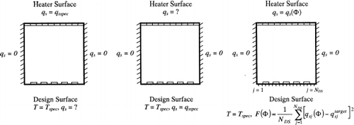
Two alternative methods have been developed that overcome the shortcomings of the forward design technique. In the inverse design technique, the designer specifies both the temperature and the heat flux distributions over the design surface, while the heater settings remain unspecified, as shown in (b). (This is the explicit formulation of the inverse problem, since both boundary conditions over the design surface are explicitly enforced.) The resulting problem is mathematically ill-posed, and special numerical techniques must be employed to solve the corresponding set of ill-conditioned linear equations. These methods only require a single iteration to find a solution, although it is sometimes a non-physical one. Harutunian et al. [Citation1] first used inverse methods to design a 2-D radiant enclosure consisting of diffuse-grey walls and containing a transparent medium. This technique has since been applied to design enclosures containing participating media [Citation2], specularly reflecting surfaces [Citation3], and multimode heat transfer effects [Citation4].
Recently, optimization methods have also been adopted to design radiant enclosures. These methods work by minimizing an objective function, F(Φ), that is defined in such a way that the minimum of the objective function corresponds to the ideal design configuration. The minimization is accomplished by iteratively varying a set of design parameters, Φ, that control the system configuration; in this application, the design parameters control the heat flux distribution over the heater surface. In the optimization design technique, the inverse design problem is solved in its implicit form, since only one of the two known boundary conditions is enforced over the design surface. As shown in , the designer first specifies the temperature distribution over the design surface, while the objective function is defined as the variance between the desired heat flux distribution and the heat flux distribution produced by a particular set of heater settings, evaluated at N DS discrete points over the design surface. The objective function is then minimized using specialized numerical algorithms, which make intelligent perturbations to the heater settings at each iteration based on the local topography of F(Φ). In this way, the heater settings that produce the desired heat flux and temperature distribution are quickly identified. Optimization has only recently been applied to design radiant enclosures; Fedorov et al. [Citation5] and Daun et al. [Citation6] used optimization methods to determine the heater settings that produce the desired heat flux and temperature distribution over the design surface of a radiant enclosure. Daun et al. [Citation7] also used these methods to solve for the geometry of a diffuse-walled enclosure that results in a desired radiosity distribution over the design surface.
The purpose of this article is to demonstrate how inverse and optimization methods are used to design radiant enclosures. Both techniques presented here are based on the infinitesimal-area method developed by Daun and Hollands [Citation8], and are in a format appropriate for the analysis of 2-D radiant enclosures. The inverse design problem is solved by truncated singular value decomposition (TSVD), while the optimization is carried out using Newton minimization. The forward design methodology is first presented followed by the inverse and optimization methodologies, respectively. Finally, the inverse and optimization design methodologies are demonstrated and compared by applying them to design a 2-D radiant enclosure.
2. Forward Design Methodology
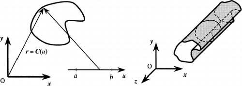
The forward design methodology is based on the infinitesimal-area technique of Daun and Hollands [Citation8]. The first step in the analysis is to identify a suitable parametric representation for the enclosure geometry. In particular, the enclosure geometry is defined by
Once the enclosure is represented parametrically, the equation governing the radiosity distribution can be formed. The radiosity distribution is governed by a Fredholm integral equation of the second kind,
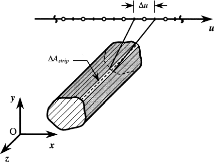
Analytical solutions to integral equations are usually not tractable, so Eq. (Equation2) must be solved numerically. The first step is to discretize the parametric domain into N elements, with the ith element centered at u i with a width Δu i . Each of these discrete elements corresponds to an infinitely long strip of finite width on the enclosure surface, as shown in . If the radiosity is assumed to be uniform over these strips, Eq. (Equation2) can be rewritten in discrete form,
3. Inverse Design Methodology
In contrast to the forward design methodology where only one thermal boundary condition is specified over each surface, the inverse design method enforces both the temperature and heat flux distributions over the design surface, while the boundary conditions over the heater surface remain unspecified.
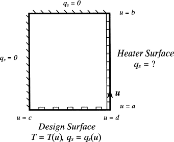
Suppose that the enclosure surface is parameterized so that a ≤ u<b corresponds to the heater surface, b ≤ u<c corresponds to surfaces where either q s (u) or E b (u) is known, and c ≤ u<d corresponds to the design surface. Such an enclosure is shown in . First, the radiosity distribution over the design surface is found immediately from
Analytical solutions to Eqs. (Equation10) and (Equation11) are usually not tractable, so a numerical technique must be used to solve the radiosity distribution. As before, the parametric region is discretized to form N elements. Let elements i = 1, … , k correspond to the heater surface, elements i = k + 1, … , m correspond to the surfaces where either q s (u i ) or T(u i ) is known, and elements i = m + 1, … , N correspond to the design surface, where q o (u i ) is known. By assuming a uniform radiosity distribution over each element, Eqs. (Equation10) and (Equation11) can be rewritten in discrete form:
Writing Eqs. (Equation12) and (Equation13) for the elements with unknown radiosities, i = 1, …, m, results in a system of m linear equations containing m + k unknowns, the extra k unknowns due to the unknown heat flux terms in Eq. (Equation12). As before, these equations can be rewritten as a matrix equation,
Since there are more unknowns than equations, matrix A admits an infinite number of solutions so traditional linear algebra techniques cannot be used to solve Eq. (Equation14). Instead, special regularization techniques are employed to select solutions with desirable properties from this infinite set, in general by minimizing the norm of x . These include Tikhonov regularization, conjugate gradient regularization, and truncated singular value decomposition (TSVD); Hansen [Citation9] describes these techniques in detail. Although each of these methods can be used in the present application, TSVD offers the most insight into the nature of the problem and is thus demonstrated here.
The TSVD method is based on the singular value decomposition of the A matrix,
4. Optimization Methodology
Unlike the methods discussed in the previous section, optimization methods solve a well-posed “forward” design problem using sophisticated techniques that limit the number of times the radiosity distribution must be calculated in order to find a viable solution to the design problem. The goal of design optimization is to minimize an objective function, F(Φ), by varying a set of design parameters contained in vector Φ that specify the design configuration. The objective function is defined so that the optimum design configuration corresponds to the set of design parameters, Φ*, that minimizes F(Φ), F(Φ*) = Min[F(Φ)]. In this application, the objective function is set equal to the variance between the desired heat flux distribution and the heat flux distribution realized with particular heater settings, evaluated at N DS discrete points over the design surface:
Many different techniques have been developed to minimize objective functions. Gradient-based methods are most often used when the objective function is continuously differentiable. These methods find Φ* iteratively; at the kth iteration, a search direction p k is first chosen based on the local curvature of F(Φ k ). Next, a step size α k isre the heater settings that control the heat flux distribution over the heater surface. The heater settings that produce the heat flux distribution that best matches the desired distribution over the design surface are contained in Φ*, which is found by minimizing F(Φ).
Many different techniques have been developed to minimize objective functions. Gradient-based methods are most often used when the objective function is continuously differentiable. These methods find Φ* iteratively; at the kth iteration, a search direction p k is first chosen based on the local curvature of F(Φ k ). Next, a step size α k is iteratively; at the kth iteration, a search direction p k is first chosen based on the local curvature of F(Φ k ). Next, a step size α k is calculated, usually by performing a univariate (line) minimization on F(Φ k + α k p k ) using Newton–Raphson, bisection, or golden section techniques. The new set of design parameters are then found by taking a “step” in the p k direction:
Gradient-based methods differ on how
p
k
is chosen. Almost all methods use the first-order sensitivities contained in the gradient vector,
g
(Φ), where and some methods also use the second-order sensitivities contained in the Hessian matrix, H(Φ), where
Gill et al. [Citation10] provide an excellent summary of gradient-based optimization methods.
In this application Newton's method is used to minimize the objective function. The search direction is found by solving the equation
The first step in calculating g (Φ) and H(Φ) is to rewrite the objective function so that it is dependent on the design parameters as well as an intermediate “system response” variable, which in turn is a function of the design parameters. In this application, the objective function is rewritten as
Clearly, the most difficult part of finding g (Φ) and H(Φ) lies in calculating the heat flux sensitivities. In this application, the most efficient way to do this is by differentiating the governing equations to find the radiosity sensitivities, which are then used to find the heat flux sensitivities. The governing equation is rewritten here to demonstrate the functional dependence of the radiosity distribution on the design parameters; assuming that the surface emissivity and geometry are independent of Φ, the radiosity distribution is governed by
By following steps analogous to those used to solve Eq. (Equation2), it can be shown that the first- and second-order radiosity sensitivities are found by solving
Once the radiosity sensitivities are calculated, the heat flux sensitivities are solved by substituting the radiosity sensitivities into the partial derivatives of Eq. (Equation8),
5. Demonstration of Design Methodologies
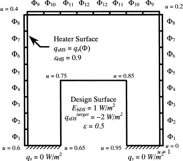
The inverse and optimization design methodologies are used to solve the design problem shown in . The goal of the analysis is to produce a uniform emissive power of E
b
= 1 W/m2 and a uniform heat flux of over the design surface, using 24 heaters located on three heater surfaces. Since the heat flux is uniform over each heater, and because the problem is symmetric, only twelve variables are required to fully characterize the heat flux distribution over the heater surface. These variables are denoted Φ
k
, for k = 1, … , 12, where Φ
k
is equal to the heat flux over the kth heater in units of W/m2.
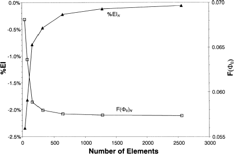
A total of 640 surface elements were used in both analyses, chosen based on the grid refinement study shown in ; 384 of those elements lie on the heater surface, 192 are on the design surface, and the remaining 64 elements are located on the two adiabatic surfaces. The grid refinement study was performed with Φ k = 1, k = 1, … , 12, which corresponds with the initial enclosure configuration of the optimization method, Φ0. It is based on the objective function defined in Eq. (Equation17), as well as the degree of energy conservation, defined as
5.1. Inverse Design Method
In order to enforce a uniform heat flux distribution over each heater, the unknown heat flux terms corresponding to each element on the heater surfaces, q si , were replaced by the heater settings, Φ i . This both reduced the degree of rank deficiency (the number of unknowns exceeds the number of equations by 12, rather than 384) and prevents the occurrence of highly oscillatory heat flux distributions that are often produced by this solution technique, and are undesirable from a design perspective.
Also, although the system of linear equations used in the forward design methodology enforces energy conservation, this is not true for the inverse formulation because the boundary conditions over the heater surfaces are unspecified. Accordingly, it is necessary to add an energy conservation equation to the A matrix,
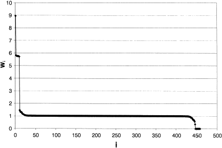
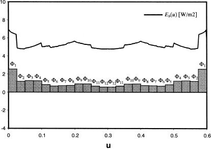
The heat flux and emissive power distribution over the heater surface obtained using all the singular values ( p = 460), all the non-zero singular values ( p = 449), and the case for p = 448 are shown in –, respectively. The corresponding design parameters are included in and the values of ||
x
|| 2 and || δ || 2 for each solution are in . In each case, the required temperature and heat flux distributions over the design surface are enforced, so and
for 0.65 ≤ u<0.95. The solution calculated using all of the singular values, shown in , has a very non-regular heat flux distribution over the heater surface, which is reflected in the large value of ||
x
|| 2 for this case in . Truncating the eleven null singular values and keeping p = 449 singular values produces a more regularized solution and a very small residual, as shown in . As more singular values are truncated, however, the solution becomes smoother but also non-physical because E
b
(u) assumes negative values over some surfaces, as shown in . At this point, too many singular values have been nullified and the original governing equations are no longer enforced, as demonstrated by the large value of || δ || 2.
FIGURE 8 Distribution of q s (u) and E b (u) over the heater surface, found using p = 460 singular values.
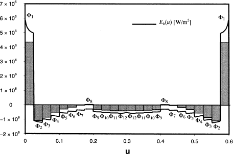
FIGURE 9 Distribution of q s (u) and E b (u) over the heater surface, found using p = 449 singular values.
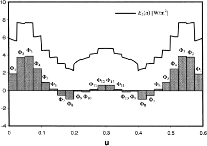
FIGURE 10 Distribution of q s (u) and E b (u) over the heater surface, found using p = 448 singular values.
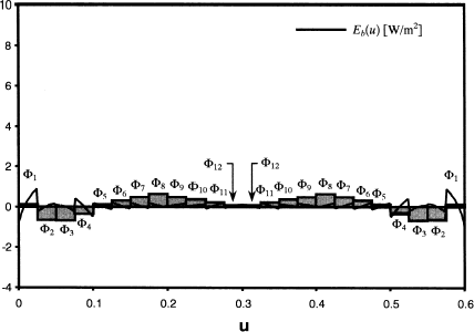
TABLE I Heater settings corresponding to – [W/m2]
TABLE II Values of || x ||2 and || δ ||2 corresponding to –
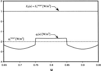
Although the solution found with p = 449 singular values is physically obtainable, it is impractical to implement in an industrial setting because some of the heaters act as heat sinks. The designer is more likely to insulate these heaters and incur the resulting error in the heat flux distribution over the design surface. In this application, Φ7, Φ8, Φ9, and Φ10 are set equal to zero while the remaining heater settings are unaltered. The heat flux distribution over the design surface is then recalculated using the forward design method. It is compared with the desired design surface conditions in .
5.2. Optimization Design Methodology
The design problem was also solved by minimizing the objective function defined in Eq. (Equation17), using Newton's method. Initially, all of the design parameters (heater settings) were set equal to unity, . Three iterations were required to identify a local minimum of the objective function, F(Φ*) = 2.92 × 10⁻⁸, corresponding to the solution illustrated in and the design parameters shown in . The heat flux distribution over the design surface closely matches the desired distribution, as shown in . Nevertheless, the solution is non-physical because E
b
(u) is negative over some regions of the enclosure surface. It is important to note, however, that this solution is mathematically feasible and satisfies Eq. (Equation6).
FIGURE 12 Heater settings found by minimizing the non-regularized objective function, Eq. (Equation17).
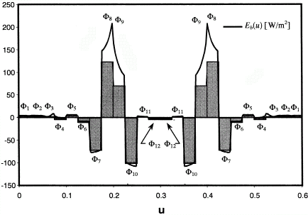
FIGURE 14 Distribution of q s (u) over the design surface, found by minimizing non-regularized and regularized objective functions.
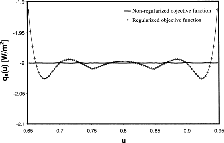
TABLE III Optimal heater settings for the regularized and non-regularized objective functions [W/m2]
A more useful solution is found by adding an additional term to the objective function equal to the L 2 norm of the design parameters, defining a new objective function:
FIGURE 13 Heater settings found by minimizing the regularized objective function, Eq. (Equation32).
In general, optimization problems with constraints are solved using constrained minimization algorithms. While very powerful, these algorithms are also more complex than unconstrained optimization and require more computational effort to implement. In this application, adding the regularization term to the original objective function enabled us to avoid using these more complicated minimization techniques.
5.3. Comparison of Inverse and Optimization Design Methods
The inverse and optimization design methodologies can be compared based on the ease of problem formulation, computational effort, and solution quality.
The inverse design methodology is somewhat more difficult to implement, since the equations governing radiosity distribution must be rewritten and rearranged. Also, the TSVD method requires the designer to have some specialized mathematical knowledge to interpret the results of the singular value decomposition. In contrast, optimization methods are based on the same set of equations used by the forward design method. Their complexity depends largely on how the sensitivities are calculated; in this application, they are easily found by direct differentiation.
Both methods require approximately the same computational effort and memory storage to solve the design problem. The TSVD method performs one singular value decomposition on the A matrix, which requires approximately the same CPU time as the single matrix inversion carried out during the optimization process. In this problem, the inverse and optimization methodologies solved the design problem in a matter of seconds.
The main difference between the two methodologies lies in the quality of the final solutions, shown in and . The optimization solution is far better than the solution obtained using the inverse design methodology because the optimization methodology can accommodate design constraints, while the inverse methodology cannot. In this application, the heat flux over the heater surface had to be non-negative, Φ k ≥ 0 for k = 1, … , 2. In the optimization methodology, this was enforced by adding a “regularization” term to the original objective function. In contrast, the inverse methodology can only be used to find the best “mathematical” solution to the problem, which is then modified to allow for practical design considerations. The ability of optimization methods to accommodate practical design constraints is one of the main assets of these techniques.
6. Conclusions
Both optimization and inverse design methods have been used to solve industrial design problems involving radiant enclosures. These methods require far less time than the forward “trial and error” method that is traditionally used to design radiant enclosures, and the quality of the solutions is usually much better.
While both methods were successfully implemented, the optimization method provided a solution that better satisfied the design requirements. This is because optimization methods can accommodate practical design constraints, while in most instances the solutions obtained using the inverse methodology can only be altered to satisfy these constraints after the primary analysis.
Acknowledgements
This work was supported by National Science Foundation Grants CTS 70545 and DMI 9702217, the Natural Sciences and Engineering Research Council of Canada, and the State of Texas.
Additional information
Notes on contributors
K.J. DaunFootnote*
*E-mail: [email protected]Notes
*E-mail: [email protected]
References
- Harutunian V. Morales J.C. Howell J.R. 1995 Radiation exchange within an enclosure of diffuse-gray surfaces: the inverse problem In: Proceedings of the ASME/AIChE National Heat Transfer Conference Portland Oregon
- França F. Morales J.C. Oguma M. Howell J.R. 1998 Inverse radiation heat transfer within enclosures with participating media In: Proceedings of the Eleventh International Heat Transfer Conference pp. 213–221 Kyongju Korea
- Ertürk , H. , Ezekoye , O. and Howell , J.R. 2002 . Comparison of three regularized solution techniques in a three-dimensional inverse radiation problem . J. Quant. Spectrosc. and Radiant Transfer , 73 ( 2–5 ) : 307 – 316 .
- Franca , F. , Ezekoye , O. and Howell , J.R. 2001 . Inverse boundary design combining radiation and convection heat transfer . J. Heat Trans. , 123 ( 5 ) : 884 – 891 .
- Fedorov , A.G. , Lee , K.H. and Viskanta , R. 1998 . Inverse optimal design of the radiant heating in materials processing and manufacturing . Journal of Materials Engineering and Performance , 7 ( 6 ) : 719 – 726 .
- Daun K.J. Howell J.R. Morton D.P. 2002 Optimization of radiant enclosures through non-linear programming In: Proceedings of the Twelfth International Heat Transfer Conference pp. 621–626 Grenoble France
- Daun K.J. Howell J.R. Morton D.P. 2001 Geometric optimization of radiant enclosures through non-linear programming In: Proceedings of the IMECE New York New York
- Daun , K.J. and Hollands , K.G.T. 2001 . Infinitesimal-area radiative analysis using parameteric surface representation, through NURBS . J. Heat Trans. , 123 ( 2 ) : 249 – 256 .
- Hansen P.C. 1998 Rank Deficient and Discrete Ill-Posed Problems SIAM Philadelphia PA
- Gill P.E. Murray W. Wright M.H. 1981 Practical Optimization Academic Press Inc. London
- Jones , M. 1999 . Inverse analysis of radiative heat transfer systems . J. Heat Trans. , 121 ( 2 ) : 481 – 484 .
- Dorai , G.A. and Tortorelli , D.A. 1997 . Transient inverse heat conduction problem solutions via Newton's method . Int. J. Heat Mass Transfer , 40 ( 17 ) : 4115 – 4127 .
