Abstract
The inverse heat conduction problem (IHCP) is used to determine the thermal boundary conditions in the case of falling film evaporation on a horizontal tube. The iterative regularization method is used to solve the inverse problem under study. The unknown functions are approximated by cubic B-splines. The inverse algorithm is verified by using the temperature data computed from the direct problem to simulate the measured temperatures for a known heat flux density. The influence of the measurement errors on the estimated heat flux density is studied. The influence of the measurement temperature locations is analyzed. The results of heat transfer through falling film evaporation around a horizontal tube by using the experimental data are presented and discussed.
Introduction
The study of single phase or two phase flows requires the knowledge of thermal boundary conditions such as local surface heat fluxes, surface temperatures or heat transfer coefficients. These parameters are important to understand the physics of phenomena in the field of evaporation, condensation or other complex flows. Recently, the IHCP have been used to determine the thermal boundary characteristics when direct measurements of surface temperatures are difficult or impossible to carry out. For this purpose various numerical algorithms have been proposed [Citation1–Citation7].
A large number of studies relating to experimental determination of heat exchange in condensation, evaporation and boiling exist in the literature (see, for example [Citation8]). In the majority of cases, the mean heat transfer coefficient is measured. Some authors determine the local heat transfer coefficients based on temperature profiles of the cooling liquid or the wall [Citation9,Citation10]. These measurements often neglect the circumferential heat conduction in the wall.
In the present article the IHCP is applied to analyze heat transfer through falling film evaporation on a horizontal tube. The iterative regularization method is used to solve the inverse problem. This method was chosen because it can easily be extended for nonlinear inverse problems which we are going to implement in future to analyze boiling phenomena. It is not the case when using an analytical solution of the direct problem and the Tikhonov regularization method (see, for example, [Citation6,Citation7]). The method is based on the conjugate gradient method to minimize the residual functional and the residual principal as the regularizing stopping criterion [Citation11].
In this article, a methodology to solve the inverse problem about a heated cylinder is presented. The numerical algorithm developed to solve the IHCP is described. The results of numerical simulations show the advantage of using an inverse analysis to determine the thermal characteristics of liquid film evaporation on a horizontal tube.
Inverse Problem Formulation
The physical model is presented in . An infinitely long cylinder of internal radius R1 and external radius R2 is considered. The temperatures at the internal radius are treated as known. The problem is considered symmetrical and the solution of the inverse problem is carried out on half of the cylinder.
FIGURE 1 Physical model.
The mathematical model of a heat conduction process in a hollow cylinder is given by the following system of equations:
(--1)
(--2)
(--3)
(--4)
(--5)
In the direct problem (Equation1
(--1) )–(Equation5
(--5) ), the heat flux density at the external surface of the cylinder (
) is unknown. The temperatures measured at nodes (rn, ϕn) inside the solid are used as an additional information on the temperature distribution in the cylinder to estimate the function
:
(--6)
The inverse heat conduction problem (IHCP) consists to estimate the function
using the conditions (Equation1
(--1) )–(Equation6
(--6) ). The solution of the inverse problem is based on the minimization of the residual functional defined by the following equation:
(--7)
where
are the temperatures at the sensor locations computed from the direct problem (Equation1
(--1) )–(Equation5
(--5) ). Formally, the inverse problem consists in minimizing the residual functional under constrains (Equation1
(--1) )–(Equation5
(--5) ).
Numerical Algorithm
The unknown heat flux density is approximated in the form of a cubic B-spline as follows:
(--8)
where m is the number of approximation parameters, pi are unknown approximation parameters and ϕi are given basis cubic B-spline. As a result, the IHCP is reduced to the estimation of a vector of parameters
.
To minimize the residual functional the conjugate gradient method is used. The function is supposed to be an element of the
space.
At each iteration, the successive improvements of desired parameters are built as follows:
(--9)
where ‘it’ is an iteration number.
is the descent parameter and a positive scalar. d it is the descent direction determined from the vector
. d it is given by the following expression:
(--10)
where the parameter
is computed as follows:
(--11)
(--12)
where
is the scalar product and
is the norm of the vector
in the space Rm of approximation parameters.
(--13)
To implement the iterative minimization procedure, the vector g is determined by the following equation:
(--14)
where G is the Gram’s matrix for basis functions.
(--15)
is the scalar product in the L2 space. The Gram’s matrix is symmetric and positive. Let J′( p) be the vector gradient of the functional J( p). The most effective method for calculating the gradient J′( p) in the Rm space is based on the adjoint problem [Citation11].
Adjoint Problem
The adjoint problem is determined by the following boundary-value problem:
(--16)
where:
(--17)
where
(--18)
(--19)
(--20)
(--21)
The gradient of the residual functional is determined by solving the adjoint problem. The symbol
represents the Dirac function.
To compute the descent parameter, the linear approximation of the descent parameter is used [Citation11]:
(--22)
where
is computed from the problem in variation at the ‘it’ iteration by using the variation of the unknown heat flux density (
).
is defined at the sensor locations
.
is approximated from a cubic B-spline as follows:
(--23)
Problem in Variation
The problem in variations is defined by the following equations:
(--24)
where
(--25)
(--26)
(--27)
(--28)
The direct problem, the adjoint problem and the problem in variations are solved by using the Gauss Seidel procedure [Citation12].
Two approaches have been used to obtain a stable solution of the inverse problem. The first one is the iterative regularization [Citation11]. According to the method, the iterative improvements of the approximation parameters is stopped with the use of the residual criteria:
(--29)
δ2 is the total measurement errors defined as follows:
(--30)
is the standard deviation for temperatures measured at the nth point.
If the number of measurement points Nmeas is relatively small, it is difficult to apply this method directly. The reason is that the sensitivity of the residual functional to variations of the approximation parameters decreases rapidly when Nmeas is decreased [Citation13].
To increase the sensitivity, the second approach based on smoothing the experimental data is used. The smoothing is realized by using B-splines using the residual criterion [Citation14]. This approach allows to interpolate the experimental temperature profiles and to compute temperatures, after smoothing, at all of the nodes on two measurement lines of the used finite difference grid.
Results and Discussion
Numerical Verification of the Solution Procedure
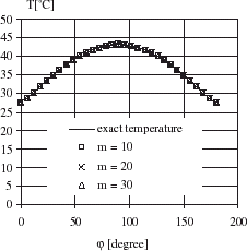
A copper horizontal tube (λ = 389 W/m2 K) having the radii R1 and R2 equal to 10 and 14 mm respectively is considered. A known heat flux density (exact heat density) is imposed at the external surface of the tube. An inner temperature profile is supposed constant (). These two boundary conditions are used to solve the direct problem in order to determine the temperature at the measurement locations. The grid of 30 nodes along the circumference and 15 nodes in the radial direction has been used. shows the exact temperature profile (Te) obtained by direct problem at radius R = 13.6 mm to simulate the measured temperatures of the interior points of the tube.
FIGURE 2 Comparison of estimated and measured temperatures.
In order to verify the present inverse procedure, the exact temperature at measurement locations is assumed equal to the measured temperatures as follows:
(--31)
The surface heat flux density is calculated from the ICHP using an inner temperature of the tube equal to 60°C and a number of measured temperature at R = 13.6 mm equal to the nodes number.
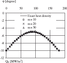
shows that the heat flux density estimated by IHCP for different approximation parameters number (m = 10, 20 and 30), is in good agreement with the exact heat flux density. The estimated temperature by IHCP at measurement locations is presented in for m = 10, 20 and 30. The maximum temperature residual is of 0.025°C. The present results are obtained by satisfying the convergence criteria J<10−10.
FIGURE 3 Comparison of estimated and exact heat flux density.
Influence of Measurement Errors
The temperature measurements are always associated with errors whose magnitude is variable according to the measurement method and the means used. The influence of the measurement errors on the variation of the heat flux density is studied by introducing temperature variations with respect to exact values obtained from the solution of the direct problem ().
FIGURE 4 Temperature profiles for ▵ = 6% and ▵ = 10%.
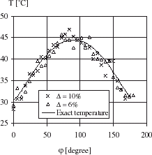
The simulated temperature measurements presented in are used in the inverse analysis to include measurement errors. The random errors of simulated measurements are added to the exact temperature obtained from the direct problem. The simulated measurement temperatures are determined from the following expression:
(--32)
where Te is the exact temperature, Te, max is the maximum exact temperature and ω is the random error of the measurement.
shows the variation of the local heat flux densities estimated by IHCP when the maximum error of the temperature measurements is ▵ = 6% or ▵ = 10%.
FIGURE 5 Estimated heat flux density for ▵ = 6% and ▵ = 10%.
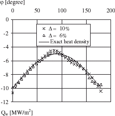
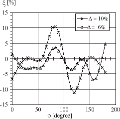
It is observed that the error (ξ) in the heat flux density predicted by the proposed inverse analysis is maximally equal to −6% for ▵ = 6% and ±11% for ▵ = 10% with respect to the exact heat flux density (). ξ is defined as follows:
(--33)
where Qw, e is the exact heat flux density and Qw is the heat flux density estimated by IHCP for ▵ = 6% and ▵ = 10%.
FIGURE 6 Variations of heat flux density for ▵ = 6% and ▵ = 10%.
The influence of measurement temperature locations is illustrated in and . The results presented in these figures are obtained from IHCP by adding the random errors (▵ = 5%) to the exact temperatures computed from the direct problem (presented in ). The local heat flux density is computed from the inverse analysis by using the measurement temperature locations at a section of radius equal to 13.6, 13.3, 13 or 12.7 mm ().
FIGURE 7 Influence of measurement temperature locations.
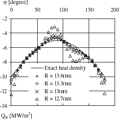
FIGURE 8 Variations of heat flux density.
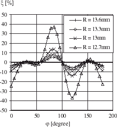
shows that for the same value of ▵ (= 5%), the error in heat flux density increases when the measurement temperature locations are moved from the external radius of the cylinder to the internal radius of cylinder. The maximum value of ξ is ± 4% for measurement temperature locations at radius R = 13.6 mm but it is ± 38% for measurement temperature locations at radius R = 12.7 mm.
Estimation of the Local Evaporation Heat Transfer Coefficient
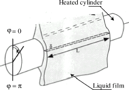
shows a scheme of a liquid film following around a horizontal evaporation cylinder. Feed water was distributed to the top of the tube (ϕ = 0°) by a thin slot at the bottom (ϕ = 180°). The cylinder is heated by an electric cartridge heater and the electric heat flux is controlled. It is difficult to measure the boundary thermal characteristics in the case when the surface is covered with a variable film thickness because the film thickness in evaporation or condensation process is generally less than 0.5 mm and it is very difficult to measure directly the velocity and temperature distributions without perturbing the flowing film. Only the wall and the bulk temperatures at the inlet and outlet of the liquid film are easily accessible.
FIGURE 9 Liquid film flowing around a horizontal cylinder.
The inverse heat conduction analysis is used to determine the local heat transfer characteristics at the external surface of the cylinder using the temperatures measured in the solid. In this study, the boundary conditions required to solve the direct problem are given in the work of Bourouni [Citation15]. The surface temperature, local heat flux density and the local heat transfer coefficient are estimated by IHCP in the case of natural convection through falling film evaporation on a horizontal cylinder. The brass experimental evaporation cylinder is of internal and external diameter equal to 10 and 22 mm respectively (). The thermal conductivity of cylinder is supposed constant (λ = 116 W/m2 K).
FIGURE 10 A measured section of an evaporation tube.
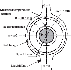
In order to compute the local thermal characteristics using IHCP, the temperatures measured for radius R1 equal to 7 mm are used as the boundary condition to solve the direct problem because the electric heat flux distribution at internal cylinder is non uniform and unknown. The temperatures measured for radius equal to 10.5 mm are used to minimize the residual functional. The computation is conducted by using the number of measurement points equal to the nodes number.
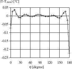
and show the local surface temperature and heat flux density profiles around the cylinder. confirms that the heat flux density distribution is not uniform. It is shown that Qw reaches maximum values at the top and bottom of the cylinder where the film thickness is infinite. illustrates the local temperature residuals resulting from this computation.
FIGURE 11 Local heat flux density distribution.
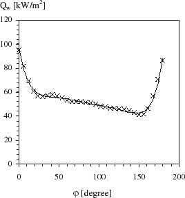
FIGURE 12 Surface temperature profile.
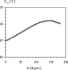
FIGURE 13 Temperature residuals vs. ϕ.
The local heat transfer coefficient is calculated from the surface heat flux density (Qw), the local circumferential wall temperature (Ts, ϕ) and the bulk water temperature (Tb) of the liquid film as follows:
(--34)
The bulk temperature Tb is the mean value of the temperatures measured at the inlet and the outlet of the liquid film.
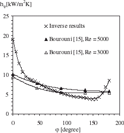
shows the local heat transfer coefficient profile around the cylinder. The bulk temperature is equal to 80°C. hϕ is highest at the top of the evaporation tube (front stagnation point) and decreases around the tube until about ϕ = 143° and tend to increase as the flow approaches the bottom of the cylinder (near stagnation point). also compares the local heat transfer coefficient estimated by IHCP for film Reynolds number equal to 4500 and hϕ profiles as reported by Bourouni [Citation15] for film Reynolds number equal to 3000 and 5000. Local heat transfer coefficients are determined by Bourouni by supposing that the surface heat flux density is uniform around the cylinder and equal to the average electric heat. The local surface temperature is calculated by Bourouni by neglecting the circumferential heat conduction. The general trend of hϕ is similar to that obtained by Han and Fletcher [Citation16] for the case of falling film evaporation on a cylinder.
FIGURE 14 Local heat transfer coefficients.
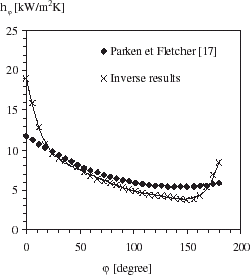
compares hϕ obtained by inverse analysis and hϕ determined by Parken and Fletcher [Citation17] using the same assumptions adopted by Bourouni. The film Reynolds number is equal to 4500 for each case. It is seen that the local heat transfer coefficient is under-estimated at the top and the bottom of the evaporation tube when the surface heat flux is supposed uniform and equal to the average electric heat.
FIGURE 15 Comparison of the local heat transfer coefficients.
Conclusions
This article shows the advantage of using IHCP to determine the thermal boundary characteristics such as surface temperature and heat flux density. Only the temperature of hot wire imbedded in the cylinder are needed to estimate the unknown surface heat density. The proposed inverse procedure can be applied to other geometry and for steady-state or transient flows. From the simulate results, it is seen that the measurement errors and the measurement temperature locations have an important influence on the estimated heat flux density. In this work, the inverse analysis is applied to a particular case liquid film evaporation flowing on a horizontal tube. In this case, the measurement of precise local heat flux or surface temperature is very difficult without perturbing the flow. The results show local heat transfer coefficient profile around the evaporation tube. They confirm that heat flux density distribution is not uniform. Consequently, the inverse heat conduction analysis is very efficient to understand the physics thermal phenomena of complex flows.
Nomenclature
Greek Symbols
Subscripts
- Throne, R, and Olson, L, 2001. The steady inverse heat conduction problem: a comparison of methods with parameter selection, J. Heat Transfer, Transaction ASME 123 (2001), p. 633.
- Chen, HT, Linn, SY, and Fang, LC, 2001. Estimation of surface temperature in two-dimensional inverse heat conduction problems, Int. J. Heat Mass Transfer 44 (2001), p. 1455.
- Chantarasiriwan, S, 2000. Inverse determination of steady-state heat transfer coefficient, Int. Comm. Heat Mass Transfer 27 (8) (2000), p. 1155.
- Abou Khachfe, R, and Jarny, Y, 2001. Determination of heat sources and heat transfer coefficient for two-dimensional heat flow – numerical and experimental study, Int. J. Heat Mass Transfer 44 (2001), p. 1309.
- Huang, CH, and Wu, JY, 1995. An inverse problem of determining two boundary heat fluxes in unsteady heat conduction of thick-walled circular cylinder, Inverse Problems in Eng. 1 (1995), p. 133.
- Maillet, D, Degiovanni, A, and Pasquetti, R, 1991. Inverse heat conduction applied to the measurement of heat transfer coefficient on a cylinder: comparison between an analytical and a boundary element technique, J. Heat Transfer, ASME 113 (1991), p. 549.
- Martin, TJ, and Dulikavich, GS, 1998. Inverse determination of steady heat convection coefficient distributions, J. Heat Transfer, ASME 120 (1998), p. 328.
- Goldstein, RJ, Eckert, ERG, Ibele, WE, Patankar, SV, Simon, TW, Kuehn, TH, Strykowski, PJ, Tamma, KK, Bar-Cohen, A, Hebertein, JVR, Davidson, JH, Bishoff, J, Kulacki, FA, Kortshaghen, U, and Garrick, S, 2001. Heat transfer – a review of 1999 literature, Int. J. Heat Mass Transfer 44 (2001), p. 3579.
- Parken, WH, Fletcher, LS, Sernas, V, and Han, JC, 1990. Heat transfer through falling film evaporation and boiling on horizontal tubes, J. Heat Transfer, Transaction ASME 112 (1990), p. 744.
- Mochizuki, S, Yagi, Y, Tadano, R, and Yang, WJ, 1990. Condensation heat transfer of nonazetropic binary mixtures (R113 + R11) in a horizontal tube, Transaction JSME, Part B 54 (1990), p. 1796.
- Alifanov, OM, Artyukhin, EA, and Rumyantsev, SV, 1995. Extreme Methods for Solving Ill-posed Problems with Applications to Inverse Heat Transfer Problems, Begell House. New York. 1995.
- Holman, JP, 1986. Heat Transfer, McGraw Hill Book Company. 1986.
- Blanc, G, Raynaud, M, and Bardon, TH, 1998. A guide for the use of the function specification method for 2D inverse heat conduction problem, Rev. Générale de la Thermique 37 (1998), p. 17.
- Loulou, T, Artiykhin, E, and Bardon, JP, 1996. "Estimation of the time dependent thermal contact resistance at the mold-casting interface". In: The 2th Int. Conf. On Inverse Problems in Eng.. Le Croisic, France. 1996.
- Bourouni, K, 1998. "Etude d’un évaporateur pour le dessalement d’eau par le procédé d’aero-évapo-condensation: expérimentation et modélisation". Aix-Marseille I, France. 1998, Thése de l’université de provence.
- Han, JC, and Fletcher, LS, 1987. "Influence of concurrent steam shear velocity on falling film evaporation and boiling on a horizontal tube". In: Proceedings of the Joint ASME-JSME Thermal Engineering Conference. 1987. p. 527.
- Parken, WH, and Fletcher, LS, 1995. "Heat transfer in thin liquid films flowing over horizontal tubes". In: Proceedings of the Fifth International Heat Transfer Conference. Munich. 1995. p. p. 415.