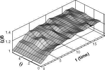
Abstract
The moving phase change interface in the latent heat energy storage system is estimated by applying a two-dimensional inverse geometry problem. The energy storage system of the vertical tube type is considered for the present inverse geometry problem. To solve the phase change problem, the boundary element method is adopted. The moving phase change interface is estimated by using the conjugate gradient method. Estimation of the phase front motion is verified by conducting the inverse analysis for an assumed phase front motion. An inverse analysis for the desired temperature distributions is executed to investigate the possibility of desired front motion control or ice monitoring. The effects of the noise levels and the thermocouple spacing on the inverse solutions are also examined.
Introduction
By using inverse analysis, engineers can obtain the thermal quantities that are difficult to measure or analyze. When the shape of the problem is unknown, the inverse geometry problem can be applied to the shape estimation.
Thermal energy storage is becoming popular as an energy saving method to solve the imbalance between day and night energy demand patterns. In particular, the latent heat energy storage system has advantages of low volume/energy ratio together with its small temperature deviation as compared with the sensible heat storage system.
In the previous work on the thermal storage system by Ismail et al. [Citation1–Citation4], a direct phase change problem on the solidification of phase change material was studied numerically.
Zabaras et al. [Citation5] estimated the thermal boundary conditions for desired phase front motion. Huang and Chen [Citation6] carried out the inverse geometry problem successfully by using the boundary element method and conjugate gradient method. Huang and Hsiung [Citation7] also conducted the optimal design problem of the cooling passage inside a turbine blade by using an inverse geometry problem.
The objective of this work is to extend the inverse geometry problem to the phase change problem in estimating the ice growth process in a vertical tube type energy storage system.
Direct Problem
Two-dimensional Phase Change Problem
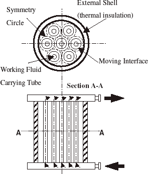
In the thermal storage system shown in , the liquid water is contained inside the external shell, while the working fluid flows into a set of tubes inside the shell. When the temperature of the working fluid is lowered below the phase change temperature, the solid–liquid interface is growing on the outside surface of the inner tube.
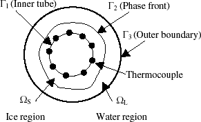
The mathematical modeling is conducted using only one inner tube of the thermal storage system as shown in . The thermal resistance of the inner tube is assumed to be negligible. To transform the formulation to the dimensionless form, the following dimensionless quantities are defined.
 where the ‘
Boundary Element Method
Since the BEM [Citation8] can readily accommodate the change of unknown boundary, the BEM is adopted for the estimation of interface shape.
After multiplying the conduction equation by the Green function, integrating the result with respect to all space and time domain, and applying Green’s second identity, the following equation is obtained.
(--2)
(--3)
(--4)
where K is the thermal diffusivity, tJ denotes the final time step, and N is a point to be analyzed. T * is Green function, and q * is the derivative of T * with respect to the normal direction; r is the length to a point on the boundary from N, and τ = tJ − t; d is the partial derivative of r with respect to normal direction.
Since the initial temperature is zero, the last integral term of the right-hand side of Eq. (Equation2(--2) ) is eliminated. Reformulating the result, the boundary element equation is obtained. By solving the boundary element equation, the unknown temperatures or heat fluxes can be obtained.
Inverse Problem
The present inverse estimation of the phase change interface is to be performed in such a way that the following functional is minimized.
(--5)
Here TS,m(t) is the calculated temperatures by the estimated interface, and Ym(t) is the measured temperatures.
Conjugate Gradient Method
The CGM iterative process is used for the estimation by minimizing the functional. The phase change interface is given as
(--6-)
(--6-)
(--6-)
where ϕ is the angle between the horizontal and outward normal direction of the unknown boundary.
is the direction of descent (i.e., search direction) given by
(--7)
where γn is the conjugate coefficient defined as
(--8)
Sensitivity Problem and Search Step Size
The sensitivity problem is obtained by replacing Γ2 by Γ2 +ΔΓ2 and T by T+ΔT in the direct problem, then subtracting the direct problem from the resultant expression, and neglecting the second-order terms.
Only one of the two boundary conditions is applied to unknown interface, since the measured temperatures are used additionally. If Eq. (Equation9d(--9-) ) is used for the boundary condition, the iteration cannot be performed because of the fluctuation resulting from the condition including a ‘vn’ term coupled with an unknown interface that is changed with iterations. Therefore, Eq. (Equation9e
(--9-) ) is used for the interface condition in this study.
The functional can be rewritten as follows:
The following expression on the search step size is obtained by differentiating Eq. (Equation10(--10) ) with respect to βn and letting by zero.
(--11)
The sensitivity function
can be obtained from the solutions of Eq. (Equation9
(--9-) ) by letting
.
Adjoint Problem and Gradient Equation
To obtain the adjoint problem, Eq. (Equation1(--1-) ) is multiplied by the
, then integrated over all space and time domain, and added the functional. In the resulting equation, the ΔJ is obtained by perturbing Γ2 by ΔΓ 2 and T by ΔT, then subtracting the original equation, and neglecting the second-order terms. This gives
(--12)
where
is the Dirac delta function. In Eq. (Equation12
(--12) ), the domain integral term is reformulated based on Green’s second identity, the boundary and the initial conditions of the sensitivity problem are utilized, and the integral including ΔT becomes zero. Then the following adjoint problem is obtained
(--13-)
(--13-)
(--13-)
(--13-)
After the introduction of the adjoint problem, the following integral term is left.
(--14)
By definition [Citation6], the functional increment can be represented as
By comparing Eq. (Equation14(--14) ) with (Equation15
(--15) ), the gradient of functional
is obtained as
In Eq. (Equation16(--16) ), the estimation cannot be performed since the initial and final values are always equal to zero. Therefore the following assumptions are introduced.
(--17)
(--18)
where Δt is the numerical time increment.
Stopping Criterion
If the problem contains no measurement errors, the traditional check condition is specified as
(--19)
where ε is a small value. However, the measured temperature data may contain measurement errors. Therefore the stopping criteria ε is obtained by using the discrepancy principle [Citation9].
(--20)
where σ is the standard deviation of the measurements, which is assumed to be a constant.
Computational Procedure
When is available, the calculation for the iteration n + 1 is summarized as below.
Table
Results
We consider one specific inverse problem whose phase change interface is assumed to be the known function to verify the methodology considered in the present work. The specified moving velocity of the interface and the relational equation between the moving velocity and the phase change interface are used for assuming the known function of the interface.
The temperature readings for this inverse problem are produced numerically by adding numerical noises to the exact solution of the direct problem. The numerically produced measurement data can be expressed as follows.
(--21)
where Yexact is the exact solution of the direct problem, σ is the standard deviation of the measurements, and ω is a random variable generated by IMSL subroutine DRNNOR; ω has a value within −2.576 and 2.576 for the 99% confidence bounds.
The reference length representing the radius of inner tube is given as unity. The thermal properties of ice in the solid and liquid regions are given as:
In order to specify an arbitrary phase change configuration, the moving velocity of a phase change interface is assumed to be
(--22)
The explicit relationships between the moving velocity and the phase change interface are given as
From the interface velocity given by Eq. (Equation22(--22) ) and the explicit relationships given by Eq. (Equation23
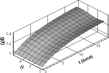
(--23-) ), the phase change interface for the validation is specified. The interface configuration specified by Eqs. (Equation22
(--22) ) and (Equation23
(--23-) ) is shown in .
The initial guessed interface configuration for the iteration is assumed to be the surface shape of inner tube, .
The difference between the exact and the estimated interface is expressed by the following shape error.
(--24)
where I and J represent the number of elements discretized by space and time, respectively.
The relative quantity of measurement errors is calculated by the following measurement error.
(--25)
Here Yavg is the average of measured data.
Validation Case Using 9-Thermocouples
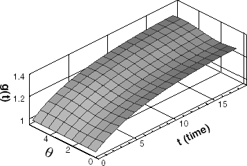
The inverse analysis using 9-thermocouples, denoted by the dots in , is performed. Without measurement errors (σ = 0), the given stopping criteria ε = 0.002 is satisfied after the estimation with 33-iterations. The estimated result of the phase change interface is shown in . In this case, the functional is converged to 0.0018 from 1900, the shape error to 0.02% from 11.0%. From Figs. and , it can be seen that the phase change interface of ice is obtained accurately in the case of no measurement errors.
Since measurement errors are always introduced in any real measurement, it is required to observe the influence of measurement errors on the inverse estimation. shows the estimated interface after 13-iterations in the case of σ = 0.05. In this case, the measurement error is calculated as 1.40%. The functional is converged to 0.37 from 1900, and the shape error to 0.27% from 11.0%. In , the estimated interface converged after 8-iterations is shown in the case of σ = 0.2. Here the measurement error is calculated as 5.70%. The functional is converged to 2.2 from 1900, and the shape error on 0.75% from 11.0%. The above results indicate that the phase change interface estimation is accurately performed even though measured temperatures contain measurement errors.
Validation Case Using 5-Thermocouples
In most real systems, there are some difficulties in installing enough sensors. Therefore, it is necessary to verify the effect of having a small number of sensors. To examine the influence of the number of sensors, the inverse analysis is performed using 5-thermocouples.
In the case with 5-thermocouples, only five-spatial information can be obtained. But the five-spatial information is not enough to express the interface for the inverse calculation. Therefore, the phase change interface is expressed more closely by interpolation between each thermocouple.
shows the estimated result of phase change interface in the case with no measurement error. It satisfies the given stopping criteria ε = 0.002 after 33-iterations. The functional is converged to 0.0018 from 1900, the shape error to 0.14% from 11.0%. Using 5-thermocouples without measurement errors, the phase change interface of ice is estimated accurately.
In , the estimated interface after 18-iterations is shown in the case of σ = 0.05. The measurement error is 1.40%, the functional is converged to 0.19 from 1100, and the shape error to 0.35% from 11.0%. As expected, the estimated interface with measurement errors is worse than that with no measurement error. But the estimated interface shows a good agreement with the exact interface.
In , the estimated interface after 12-iterations is shown in the case of σ = 0.2. Here the measurement error is 5.80%, the functional is converged to 3.4 from 1100, and the shape error to 1.1% from 11.0%. Though there are a small number of thermocouple and a large measurement error, the interface can also be estimated with good agreement.
Results on the Desired Temperature Distributions
To illustrate the ability of the present inverse estimation in operating the practical thermal storage system and monitoring the generated ice, we consider arbitrary temperature distributions on the thermocouple location. The estimations for the arbitrary temperature distributions are performed.
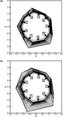
(a) shows the estimated interface configuration when imposing relatively higher temperature distribution on the first thermocouple and lower temperature distributions on the fifth and sixth. It can be seen that a thinner ice layer is generated around the first thermocouple, and a thicker ice layer around the fifth and sixth. (b) is the estimated result for the similar temperature distribution as in (a), but temperature increases more with time compared to that of (a). (b) shows that the ice growth is more active than that of (a) because of increasing temperature differences.
FIGURE 10 Estimated ice shape for higher desired temperatures at 1 and lower at 5, 6: (a) lower temperature increment; (b) higher temperature increment.
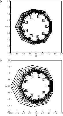
(a) illustrates the estimated interface configuration when imposing relatively lower temperature on the ninth point and increasing the temperature clockwise from that point. It can be seen that the thick ice layer is generated around the ninth thermocouple, and the thickness of ice layer decreases clockwise from that location. (b) shows the estimated result with the similar temperature distributions as in (a), but temperature increases more with time compared to that of (a). It is observed that the thickness of ice layer in (b) is thicker than that of (a).
Conclusion
In this work, the phase change interface is estimated using the inverse geometry technique by applying the conjugate gradient method (CGM) along with the boundary element method (BEM). Several cases for different numbers of sensors and measurement errors are successfully performed. Physical validity for an arbitrary temperature distribution imposed on the thermocouples is also examined. The present results show that the phase change interface can be estimated with a good accuracy by using the method considered in this work. The present work may also be used for controlling and monitoring the thermal storage system.
Nomenclature
Table
Greek Symbols
Subscripts
Superscripts
Acknowledgement
This work was supported by the research fund of Hanyang University (HY-2001).
- Ismail, KAR, and Abugderah, MM, 2000. Performance of a thermal storage system of the vertical tube type, Energy Conversion &Management 41 (2000), pp. 1165–1190.
- Ismail, KAR, Alves, CLF, and Modesto, MS, 2001. Numerical and experimental study on the solidification of PCM around a vertical axially finned isothermal cylinder, Applied Thermal Engineering 21 (2001), pp. 53–77.
- Ismail, KAR, Henriquez, JR, Moura, LFM, and Ganzarolli, MM, 2000. Ice formation around isothermal radial finned tubes, Energy Conversion & Management 41 (2000), pp. 585–605.
- Ismail, KAR, and Goncalves, MM, 1999. Thermal performance of a pcm storage unit, Energy Conversion & Management 40 (1999), pp. 115–138.
- Zabaras, N, Ruan, Y, and Richmond, O, 2000. Design of two-dimensional Stefan processes with desired freezing front motions, Numerical Heat Transfer, B 21 (2000), pp. 307–325.
- Huang, CH, and Chen, HM, 1999. Inverse geometry problem of identifying growth of boundary shapes in a multiple region domain, Numerical Heat Transfer, A 35 (1999), pp. 435–450.
- Huang, CH, and Hsiung, TY, 1999. An inverse geometry problem of estimating optimal shape of cooling passages in turbine blades, International Journal of Heat and Mass Transfer 42 (1999), pp. 4307–4319.
- Brebbia, CA, and Dominguez, J, 1992. "Boundary elements; an introductory course". In: McGraw-Hill. New York. 1992, 2nd. Edn..
- Alifanov, OM, 1974. Solution of an inverse problem of heat conduction by iteration methods, Journal of Engineering Physics 26 (4) (1974), pp. 471–476.
