Abstract
In this paper, the development of an automated umbilical cord blood (UCB) collection system is presented. The overall control system is comprehensive, comprising of various selected control and instrumentation components, integrated within a configuration of hardware architecture centered around a dSPACE DS1002 Digital Signal Processing (DSP) board. The hardware architecture, software development platform, user interface, and all constituent control components will be elaborated on in the paper.
1. INTRODUCTION
Umbilical cord blood (UCB) is an increasingly important rich source of stem cells Citation[1]. Stem cells can divide to create:
new red blood cells that carry oxygen to the brain;
new white blood cells used in the body's immune system;
new platelets that help blood clotting.
Therefore, these cells can be used for the treatment of over 45 malignant and non-malignant diseases, including certain cancers such as leukemia, and immune and genetic disorders. UCB provides a readily available source of stem cells for transplantation in many situations where bone marrow is now used. There are many advantages to using UCB instead of other sources of stem cells such as bone marrow and peripheral blood:
There is no risk involved in collection of UCB.
UCB is much easier to collect and harvest without the risks of general anesthesia required to harvest bone marrow.
UCB is readily available when needed if it is properly collected and stored at birth.
UCB is often more compatible when used in transplants.
UCB has lower procurement costs.
UCB has demonstrated broader potential clinical applications for improving neural repair and bone and tissue growth.
The importance of UCB is now widely recognized. Blood centers worldwide now collect and store UCB after the delivery of a baby upon the parents' request. The UCB may become extremely useful and indispensable at a later stage in saving the life of the newborn baby. However, one problem associated with UCB is that its collection is a one-time possibility and the amount of blood that can be collected is limited using current ways of blood collection, which include syringe-assisted and gravity-assisted methods Citation[2]. These methods are mainly manually carried out. Apart from being a tedious and difficult process, the current ways of extracting the blood also inherit a high risk of unnecessary contamination.
In this paper, the development of an automated UCB collection system (patent pending) will be presented. The system is easy to use, can be readily sterilized and it yields an improved collected UCB volume compared to prior art. It is designed with the constraints of a typical delivery room in mind. The paper will elaborate on the hardware and software aspects of the system and the operational function associated with each of the components. Results from six placentas will be presented to show the relative advantage of the developed system.
2. CONSTRUCTION OF THE AUTOMATED UCB COLLECTION SYSTEM
The system comprises the following four components:
a placenta tray with umbilical cord positioner;
an air-tight chamber with a controlled and distributed pneumatic pressure application system;
an adjustable and integrated vibratory structure;
an open-architecture software control system fulfilling the functionalities of the overall system.
These four components are modular in nature so that each can be modified or replaced, while the other components remain in use. This feature facilitates repeated operations using the same device. Collectively, the four components form an electro-mechanical apparatus that is able to manipulate the placenta via a combination of high frequency vibration and controlled pneumatic pressure, to maximize the flow of blood from the placenta to a collection tube. In addition, all the key components, which may be directly or indirectly in contact with the placenta, can be readily sterilized and are also designed to filter contaminants from the collected blood.
In this section, the hardware and software aspects of the automated UCB collection system will be described in details in sections 2.1 and 2.2. The user interface for the overall system will also be illustrated in section 2.3.
2.1. Hardware Architecture
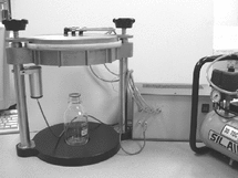
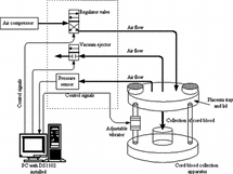
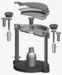
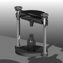
The hardware architecture and the pictorial diagram of the UCB collection system are shown in and , respectively. and show the exploded view of the various hardware components of the UCB collection system. Each of these components are carefully designed to fulfill a specific function contributing to the overall operation of the UCB collection system.
2.1.1. Placenta Tray and Umbilical Cord Positioner
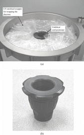
The placenta tray (Figure ) is a modular slightly-reverse sloping (cone-shaped) component, which is an integral part of the overall stainless steel support structure. It serves as the support base for the placenta, with the maternal side facing upward, the fetal side facing downward, and the umbilical cord, originating from the fetal side, passing through the ventura of the funnel-shaped element, which is formed by a plastic umbilical cord positioner (Figure ). The placenta can be wrapped in an ultraviolet-sterilized wrapper prior to being placed in the tray to reduce the possibility of contamination. Still, the umbilical cord positioner, walled with a disposable absorbent, will also serve as a mechanical filter against contaminated blood from the surfaces of the placenta dripping through the ventura.
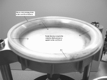
A variable thickness silicon pressure pad () with an integral sealing ring can be snapped into position above the maternal side of the placenta in placenta tray. This pad fulfills a three-fold function. It serves to keep the slippery placenta in place, air-seals the gap between the pressure application lid and the placenta tray, and its deliberate varying thickness design will evenly distribute pneumatic pressure radially across the maternal side of the placenta from the periphery of the placenta towards the umbilical cord at the center, when the pneumatic application system is applied ().
2.1.2. Pneumatic Pressure Application System
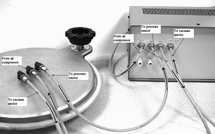
The pneumatic pressure application system () comprises a pressure application lid that is snapped onto the placentra tray. Together with the placenta tray and positioner, they form an air-tight chamber. The sealing ring, which is an integral part of the pressure pad, is used to eliminate air-leakage. The lid houses three interfaces to standard air tubings. One interface is connected to an air tubing from a compressed air source, which can be an air cylinder or an air compressor. The second interface is connected to a pressure sensor (), which provides the current value of the pressure in the air-tight chamber and completes the control loop. The actual chamber pressure can be varied to follow a desired profile by manipulating directly a servo valve opening via a pressure controller. In this way, a massaging action is delivered to the placenta to induce a faster and smoother flow of blood from the placenta. This sensor also acts as a safety feature, such that in the situation whereby the pressure within the air-tight chamber exceeds a certain threshold value, the whole system would be shut down. The third interface is connected to a vacuum ejector, which provides a fast release of pressure within the air-tight chamber to achieve the massaging effect.
2.1.3. Vibratory Structure
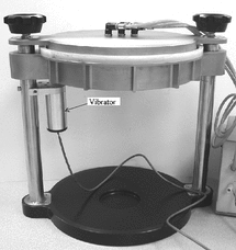
The stainless steel structure is integrated with a vibrator (), which generates high frequency vibration to the entire structure. In this way, the placenta is kept in a naturally inclined position at all times. Bottlenecks and clots impeding blood flow can be reduced. The amount of vibration is adjustable via the vibration controller.
2.1.4. DSP Board
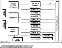
The block diagram of the dSPACE DS1102 DSP board Citation[3] (manufactured by dSPACE Digital Signal Processing and Control Engineering GmbH) used in the automated cord blood collection system is shown in . The dSPACE DS1102 DSP board is used as the main computing unit. It is a single board system, which is specifically designed for development of high-speed multivariable digital controllers and real-time simulations in various fields. The DS1102 is based on the Texas Instruments TMS320C31 third generation floating-point DSP, which builds the main processing unit, providing fast instruction cycle time for numeric intensive algorithms. It contains 128 K words memory fast enough to allow zero wait state operation. Besides these, the DS1102 DSP board supports a total memory space of 16 M 32-bit words including program, data and I/O space. All off-chip memory and I/O can be accessed by the host even while the host is running thus allowing easy system setup and monitoring. The TMS320C31 is object-code compatible to the TMS320C30. The DSP is fully supplemented by a set of on-board peripherals frequently used in digital control systems. Analog to digital and digital to analog converters, a DSP-microcontroller based digital-I/O subsystem and incremental sensor interfaces make the DS1102 an ideal single board solution for a broad range of digital control tasks.
2.2. Software Development Platform
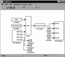
The DS1102 DSP board is well supported by popular software design and simulation tools, including MATLAB and SIMULINK Citation[4], which offer a rich set of standard and modular design functions for both classical and modern control algorithms. The overall SIMULINK control block diagram customized for the cord blood collection system is shown in .
Upon a successful automatic code generation from the SIMULINK control block diagram, the controller will then be downloaded and executed on the dSPACE DSP board. The user interface (discussed in Section 2.3) allows for user-friendly parameters tuning/changing and data logging during the operations. The control parameters can be changed on-line, while the system is in operation. All the changes made by the user can be observed simultaneously on the display.
2.3. User Interface
An open-architecture software control system fulfills the overall functions of the system. It can be programmed to give different chamber pressure profiles. Closed-loop control ensures the pressure is precisely controlled to track desired profiles. Alarm and safety features can be implemented to maintain the chamber pressure within acceptable thresholds. The aim of the user interface is to enable the operation of the UCB collection system and to monitor the whole process.
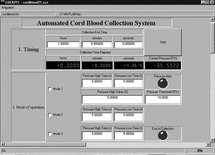
The user interface is designed as a virtual instrument panel based on the dSPACE COCKPIT instrumentation tool Citation[5]. COCKPIT (a peripheral design tool for graphical output and interactive modification of variables, for applications running on dSPACE DSP boards) is a comprehensive design environment where designers can intuitively manage, instrument, and automate their experiments and operations. COCKPIT is seamlessly integrated within the dSPACE development platform. It can realize real time data acquisition, online parameterization and provide an easy access to all model variables without having to interrupt the running operations. The entire user interface design is achieved simply via drag and drop operations from the instrument selector provided. This greatly speeds up the design process and helps to avoid standard design pitfalls associated with line programming.
shows the user interface customized for the UCB collection system.
3. TEST RESULTS
According to Citation[6], the current ways of UCB collection typically recovers 20–40 ml. Apart from obstetric factors such as infant weight and time of collection, the procedure involved and the equipment used to perform the collection influence the final yield.
The apparatus has been tested on six delivered placentas. The average total volume of UCB collected is 58.25 ml. The device was also tested for incremental improvement. It was applied after the syringe-assisted collection procedure was exhausted. The average device yield is 28.6%, representing the incremental volume over total volume collected.
4. CONCLUSIONS
An automated UCB collection system has been developed to enable an efficient umbilical cord blood (UCB) collection process. The hardware architecture, software development platform, user interface, and all constituent control components are elaborated on in the paper. The overall control system is comprehensive, and designed with the constraints of the typical delivery room in mind. The control and instrumentation components, integrated within a configuration of hardware architecture centered around a dSPACE DS1002 DSP processor board, collectively achieves the objective function and yield an improved volume of UCB according to real tests carried out on freshly delivered placentas.
REFERENCES
- Cairo, M.S., Wagner, J.E. (1997). Placental and/or umbilical cord blood: An alternative source of hematopoietic stem cells for transplantation. Blood 90: 4665–4678. [CSA]
- Bertolini, F., Lazzari, L., Lauri, E. (1995). Comparative study of different procedures for the collection and banking of umbilical cord blood. J. Hematother Stem Cell Res. 4: 29–36. [CSA]
- dSPACE DS1102 User's Guide (1996). Document Version 3, dSPACE.
- The Mathematics Laboratory (2005), http://www.mathworks.com.
- COCKPIT User's Guide (1996). Document Version 3.2, dSPACE.
- McCullough, J., Herr, G., Lennon, S. (1998). Factors influencing the availability of umbilical cord blood for banking and transplantation. Transfusion 38: 508–510. [CSA], [CROSSREF]
