
Abstract
The objective of this work was to examine the mechanical strength properties of polycarbonate toecaps designed for commercially available protective footwear, subjected to repeated impacts simulating workplace conditions. The effects of impacts on the toecaps were expressed as the height of toecap clearance, which has a direct bearing on the safe use of protective footwear. Changes in toecap geometry were evaluated using an originally developed methodology taking into consideration the requirements of Standard No. EN ISO 22568-2:2019. Additionally, external and internal sides of toecaps were scanned in three dimensions after each impact and reverse engineering was used to analyze deformations in toecap geometry by comparing the shape of the toecaps before and after impact. Three-dimensional scanning made it possible to measure the remaining safe distance for toes between the footwear sole and the impacted toecap surface, which is an indicator of the protective properties and safety of toecaps during use.
1 Introduction
If polycarbonate toecaps are subjected to repeated impacts, the distance between their upper surface and the footwear sole will be reduced, which will also compromise their protective properties. Toecaps are widely used to protect workers’ feet against the mechanical hazards present in the workplace. Specifically, they are placed in the front part of footwear to prevent crush trauma from falling objects [Citation1–3]. Footwear with toecaps is used in many sectors of industry, especially in manufacturing, automotive service and repair, as well as warehousing and transportation [Citation4]. Thus, evaluation of the protective properties of toecaps is important as a more comprehensive assessment method may improve the safety of workers in a variety of industries. The risks associated with an impact in the workplace depend on the weight, shape and material of the falling object, as well as the height at which the fall is initiated. Of importance is also the number of such impacts [Citation5].
Toecaps may be made from metals and composites, and especially polymeric composites, e.g., those reinforced with fiberglass, carbon or aramid fibers, or nanoparticles [Citation6,Citation7]. The weight of toecaps is of the essence as they constitute one of the heaviest elements of footwear, accounting for up to 35% of its overall mass [Citation6]. As compared to metals and their alloys, composites are lighter and exhibit greater crack resistance [Citation8]. While steel and aluminum toecaps are highly resistant to mechanical factors, they significantly contribute to footwear mass [Citation9]. Metal and composite toecaps also demonstrate some significant differences in terms of their functional properties [Citation10–12].
Toecaps must meet a number of protective and functional requirements stipulated in EU Regulation 2016/425 [Citation13]. A key protective parameter is impact resistance, which is tested pursuant to the harmonized Standard No. EN ISO 22568-2:2019 [Citation14]. According to the methodology described in that standard, the tested toecaps are subjected to only one impact of a striker with an energy of 100 or 200 J (for protective and safety toecaps, respectively), after which the clearance under the toecap is measured.
Laboratory evaluation of the performance of protective footwear with toecaps does not fully reflect the actual workplace conditions. The standardized toecap test methods used for evaluating protective properties have an empirical and simplified nature. As a result, in real-life situations, footwear equipped with toecaps certified by laboratory procedures may provide lower than expected levels of safety [Citation15]. Other authors have reported discrepancies between the performance of protective footwear under laboratory and actual workplace conditions [Citation16]. Thus, in order to improve the safety of workers wearing protective footwear, testing methods should be improved to account for real-life factors in the workplace.
While there are no literature reports on the effects of multiple impacts on internal toecap structure, such impacts may affect the actual protective performance of toecaps in real-life work conditions. It has been reported that defects caused by a single impact (delamination, cracking and deformation) may compromise the protective parameters of toecaps, making the footwear unsafe to use in the workplace [Citation5].
Three-dimensional (3D) analysis confirmed that impact-induced deformations sustained by toecaps during footwear use may compromise the safety of workers’ feet. The long-term use of footwear with polycarbonate toecaps implies the risk of multiple mechanical impacts potentially affecting their protective parameters. Repeated impacts may also reduce the distance between the upper toecap surface and the footwear sole. It is suggested that polymeric toecap strength tests should involve a series of impacts, rather than a single impact, to better simulate the actual mechanical hazards that occur in the workplace.
The present study tested the mechanical strength of polycarbonate toecaps subjected to repeated impacts. The objective was to evaluate the effects of impacts on the toecaps expressed as the height of toecap clearance, which has a direct bearing on the safe use of protective footwear. Statistical analysis revealed significant differences in the geometry of such toecaps before and after impacts. Changes in polycarbonate toecap geometry were also evaluated using 3D scanning to determine how consecutive impacts gradually decreased the safe distance (clearance) between the footwear sole and the lowest point of the deformed upper part of the toecap.
2 Materials and methods
2.1 Materials
Until recently, the toecaps used in protective footwear were predominantly made of metal, mostly steel or aluminum. However, due to advances in materials science and engineering in the area of lightweight composite materials with improved mechanical parameters, polymeric toecaps have become increasingly popular [Citation9]. It should also be noted that metal toecaps may affect heat transfer and prevent moisture dissipation during footwear use, thus impairing user comfort. Significant differences between metal and composite toecaps in this respect have been identified in a previous study [Citation10]. The type of toecap material influences the insulation properties of protective footwear, which is especially relevant for work in cold environments. Metal toecaps have been found to lead to inferior insulation and thermal discomfort as a result of toe cooling [Citation11]. Therefore, workers tend to increasingly use toecaps made of non-metallic materials.
Given the aforementioned, the present study examined toecaps made of a popular thermoplastic polymer. Fourier transform infrared spectroscopy–attenuated total reflectance (FTIR–ATR) revealed that the studied toecaps were made from polycarbonate. The toecap material and its chemical composition were characterized in other work by the authors [Citation17]. The study involved toecaps extracted from commercially available footwear produced by a German manufacturer of personal protective equipment (PPE), which are characterized in Table .
Table 1. Description of the toecaps used in the study.
2.2 Testing
In the standard approach to evaluation of toecap resistance to impacts described in Standard No. EN ISO 22568-2:2019 [Citation14], the tested toecaps are subjected to one impact of 100 or 200 J, depending on the claimed performance level. While standard tests assess only changes in the height of a modeling clay cylinder positioned inside the impacted toecaps, in real-life situations toecaps may be exposed to multiple mechanical loadings in the workplace. The presented study used 3D dimensioning analysis to determine the distance between the upper polycarbonate toecap surface and the footwear sole to assess the mechanical resistance of polycarbonate toecaps subjected to repeated impacts.
2.2.1 Resistance to repeated impacts
Studies were conducted according to a novel methodology developed on the basis of Standard No. EN ISO 22568-2:2019. The applied impact tester (Pegazil by Zipor, Portugal) was equipped with a mechanism that caught the striker following the first impact to prevent secondary rebound impacts. The striker was 60 mm long. The two 40-mm-long rectangular facets of the impact head were at an angle of 90 ± 1°. The tip was rounded with a radius of 3 ± 0.1 mm, as shown in Figure . The striker was made of steel with a Rockwell hardness of 60 HRC, and positioned parallel to the toecap holder (perpendicular to the toecap).
Figure 1. Shape and parameters of the striker used for repeated impact testing of toecaps.
Note: Set-up based on Standard No. EN ISO 22568-2:2019 [Citation14].
![Figure 1. Shape and parameters of the striker used for repeated impact testing of toecaps.Note: Set-up based on Standard No. EN ISO 22568-2:2019 [Citation14].](/cms/asset/66feb417-2e0b-4796-8afe-d50ee31abb47/tose_a_1796295_f0001_oc.jpg)
The test protocol consisted of five impacts applied with an energy of 200 J. Toecap deflection and deformation were used to determine two parameters:
change in the height of a modeling clay cylinder placed inside the toecap (before and after impact);
change in internal toecap width (before and after impact).
The hand-made modeling clay cylinder, prepared in accordance with Standard No. EN ISO 22568-2:2019, was 30 mm high (h0) and 25 mm in diameter. The midline of the polycarbonate toecap was determined using a ruler (Format Professional Quality, Germany). The cylinder was placed on the midline (test axis), with a third of its diameter remaining outside the rear edge of the toecap. The change in the height of the cylinder (h1) was measured after each of five impacts, as shown in Figure . Based on statistical analysis, the cylinder height measurement error was estimated at ± 0.03 mm.
Figure 2. Method of measuring the change in the height of the modeling clay cylinder positioned inside the toecap based on Standard No. EN ISO 22568-2:2019 [Citation14].
Note: h0 = height of hand-made modeling clay cylinder; h1 = change in the height of the cylinder.
![Figure 2. Method of measuring the change in the height of the modeling clay cylinder positioned inside the toecap based on Standard No. EN ISO 22568-2:2019 [Citation14].Note: h0 = height of hand-made modeling clay cylinder; h1 = change in the height of the cylinder.](/cms/asset/91dacfd8-77e8-4825-a37c-9f6dea890781/tose_a_1796295_f0002_ob.jpg)
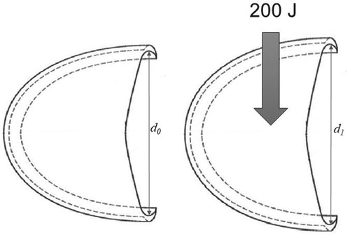
The initial (d0) and post-impact (d1) internal toecap widths were determined using a digital caliper (Vis Sp. z o.o., Poland), as shown in Figure .
Figure 3. Method of measuring the internal toecap width.
Note: d1 = initial internal toecap width; d0 = post-impact internal toecap width.
2.2.2 Measuring toecap deformation by means of 3D scanning
To evaluate changes in geometry resulting from repeated impacts with an energy of 200 J, the inner and outer sides of the toecaps were scanned in three dimensions four times. Scanning was not performed after the fifth impact, which caused toecap failure.
Computer-aided design (CAD) models, used as reference files for further end-of-service life assessment, were generated using a Perceptron V4i laser scanning probe and an Infinite 2.0 articulating arm (CimCore, USA), as shown in Figure , with the technical parameters presented in Table .
Figure 4. Three-dimensional toecap scanning set-up, including the probe.
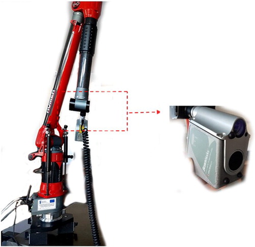
Table 2. Technical parameters of the toecap scanning set-up.
At the beginning of the tests, the overall measurement error was determined for the experimental set-up. It was defined as the geometric sum of independent partial error components attributable to the laser scanning probe, the six-axis articulating arm and distorting factors, such as changes in external illumination, reflections and changes in the scanned surface caused by consecutive impacts. Moreover, the overall error was also affected by the accuracy of models generated in .STL format from a cloud of points. Based on statistical analysis of partial errors, the overall error of the measurement method was estimated to be ± 0.1 mm.
Polycarbonate toecap scans were used to generate 3D images in .STL format to compare the shape of toecaps before and after impacts. Graphical comparisons were done by means of specialist computer programs Geomagic Studio version 11 and Geomagic Qualify version 11, which are typically used in advanced reverse-engineering applications.
2.3 Statistical analysis of impact effects
Measurements of impact effects were statistically analyzed using SPSS version 25.0 to determine changes in toecaps before and after consecutive impacts in terms of two parameters:
height of the modeling clay cylinder placed inside the toecaps;
internal toecap width.
The statistical methods included analysis of variance (ANOVA) with a-posteriori bootstrapping with 1000 replicates. Post-hoc comparisons were performed using the Bonferroni method.
3 Results and discussion
3.1 Analysis of resistance to repeated impacts
The results obtained concerning mechanical resistance to repeated impacts of polycarbonate toecaps are presented in Table together with the basic statistics. In addition, photographic images of toecaps following consecutive impacts are presented in Table .
Table 3. Descriptive statistics for modeling clay cylinder height and internal polycarbonate toecap width after each of the five impacts.
Table 4. Photographs of polycarbonate toecaps subjected to repeated impacts.
In the experiments, the height of the modeling clay cylinder placed inside the toecaps decreased by 28% after the first impact, which conformed to the requirements of Standard No. EN ISO 22568-2:2019 [Citation14]. The deformations after the second, third, fourth and fifth impacts were 40, 51, 60 and 70%, respectively.
Furthermore, the first impact caused a 5% increase in internal toecap width. After the second, third, fourth and fifth impacts, toecap width increased by 7, 9, 12 and 34%, respectively. The changes in toecap width are attributable to the deformations and reduced height of the toecaps caused by mechanical loadings. It should be noted that the observed alterations in toecap width may additionally compromise footwear safety.
The experiments revealed some major changes in polycarbonate toecap geometry due to impacts. The most dramatic change was observed after the fifth impact of 200 J, which caused toecap failure. Already after the first impact, the middle region of the toecap exhibited whitening, which may indicate macromolecule reorientation in the direction of the tensile stress exerted by impact energy. Repeated impacts made macromolecule orientation more visible on both the inner and the outer surfaces of the toecap.
Statistical analysis of the obtained results confirmed significant deformations of polycarbonate toecaps following impacts, as presented in Table .
Table 5. Results of the analysis of variance of the height of modeling clay cylinder inside the toecap and the internal toecap width.
Statistical analysis revealed a significant effect of the number of impacts on internal polycarbonate toecap clearance, as reflected by decreasing modeling clay height: toecap clearance was clearly smaller after the fourth and fifth impacts as compared to the first, second and third impacts. The number of impacts also significantly affected the internal toecap width: after the third impact it was greater than after the first and second impacts, and after the fifth impact it was greater than after impacts one to four.
3.2 Analysis of toecap deformations by means of 3D scanning
Analysis of changes in toecap geometry revealed that the polycarbonate toecaps maintained upper surface integrity during the first four impacts of 200 J, but they failed upon the fifth. Thus, changes in geometry after the last impact were not evaluated by 3D scanning.
In the first step, impact-induced shape deviations were compared to intact toecaps. Figures present geometry analyses in which various degrees of plastic deformation are visualized by means of a color scale.
Figure 5. Three–dimensional analysis of toecap deformation after the first impact: (a) outer side; (b) inner side.
Note: The full color version of this figure is available online.
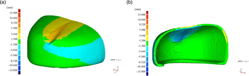
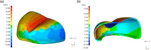
Figure 6. Three–dimensional analysis of toecap deformation after the second impact: (a) outer side; (b) inner side.
Note: The full color version of this figure is available online.
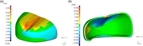
Figure 7. Three–dimensional analysis of toecap deformation after the third impact: (a) outer side; (b) inner side.
Note: The full color version of this figure is available online.
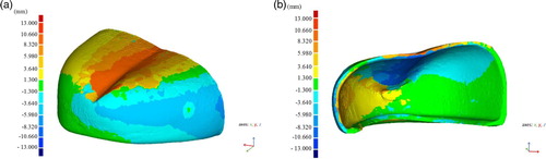
Figure 8. Three–dimensional analysis of toecap deformation after the fourth impact: (a) outer side; (b) inner side.
Note: The full color version of this figure is available online.
The objective of geometry analysis was to determine the distance between the plane supporting the user’s foot (the top surface of the footwear sole) and the lowest point of toecap deformation. The ‘Best Fit’ function was used to define ‘Plane 1’ as the footwear sole. Subsequently, the ‘Cross-Section’ function was employed to gradually increase the distance between Plane 1 and a plane parallel to it until the other plane reached the lowest point of toecap deformation. Thus, the parallel plane found in this way was adopted as the upper limit of the area unaffected by toecap deformation (safe clearance). Finally, measurements were performed using the ‘3D Dimensioning’ function. The results of 3D analyses of toecaps subjected to repeated impacts are shown in Figure .
Figure 9. Three–dimensional dimensioning analysis after repeated impacts.
Note: The full color version of this figure is available online. h1 = change in the height of the cylinder.
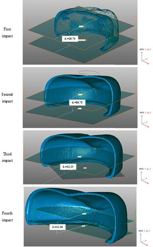
The exact position of Plane 2 was determined by analyzing cross-sections every 0.01 mm in order to precisely delimit the safe area free of any vertical toecap deformation. Figure presents graphical representations of deformations following four consecutive impacts based on analysis of 3D images. The Z value represents the safe distance (mm) between Planes 1 and 2 (see Figure ).
Figure 10. Decreasing clearance between the footwear sole and the upper part of toecaps due to increasing toecap deformations after consecutive impacts.
Note: The full color version of this figure is available online.
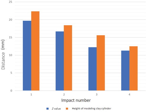
According to 3D scanning analysis, after four impacts the plastic deformation of the front part of the toecap amounted to 11.66 mm, or 51%. After the same number of impacts, modeling clay cylinder measurements revealed an elastic deformation of 17.99 mm, or 58%, for the rear part of the toecap.
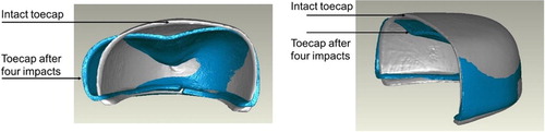
Three-dimensional models illustrating changes in toecap geometry resulting from repeated impacts are shown in Figure . The reference shape of the intact toecap is gray, while the toecap subjected to four impacts is blue. After the fifth impact, the upper toecap surface broke in half.
Figure 11. Model showing the shape of an intact toecap and the same toecap after four impacts.
Note: The full color version of this figure is available online. gray = reference shape of the intact toecap; blue = toecap subjected to four impacts.
The studied toecaps are crucial and widely used elements of protective footwear. From the user’s standpoint, it is critical for protective footwear to be adequate for the hazards present in the workplace. Therefore, the protective properties of toecaps should be evaluated under conditions that closely resemble real-life workplace situations.
Repeated impacts, which are not taken into consideration in standard testing procedures, decreased the distance between the upper surface of the toecap and the footwear sole, and led to polycarbonate toecap failure after the fourth impact of 200 J.
Other authors have used state-of-the-art technology, mostly numerical modeling and 3D scanning, to determine mechanical failure mechanisms of toecaps and to optimize their thickness and geometry with the aim of improving mechanical strength [Citation1,Citation5,Citation18–22].
The methods proposed in the present study were used to obtain a comprehensive mechanical evaluation of polycarbonate toecaps. The obtained results revealed a decreased distance between the upper polycarbonate toecap surface and the footwear sole as a result of repeated impacts, which reflected the critical conditions for the use of such toecaps. Analysis of changes in toecap geometry (the distance between the footwear sole and the maximum inward deformation of the upper surface of the toecap) was convergent with the statistical analysis of experimental data. Repeated impacts weakened the toecap material, leading to mechanical failure already after the fifth impact (Figures –, Table ).
Workers using protective footwear may be exposed to a variety of external factors, including multiple mechanical impacts to the feet. Analysis of the study results shows the importance of mechanical strength evaluation of toecaps subjected to repeated impacts simulating workplace conditions. As can be seen from Table , while the tested toecaps met the requirements of the relevant standard [Citation23], in the long term they may fail to protect the wearer from injury, as indicated by 3D scans made following repeated impacts (Figures –).
The fact that toecap deformation after impacts four and five was significantly greater than after impacts one to three shows that the mechanical strength of the toecaps was substantially compromised already by the third impact. As a result, the protective properties of the impacted toecaps deteriorated considerably, which was confirmed by 3D analysis and by their vertical and sideways deformation (Figure ) as compared to intact toecaps, which increased the risk of toe injury. Moreover, the fourth impact cracked the toecap base (Figure ), while the fifth caused complete mechanical failure.
Reverse-engineering methods provided an additional opportunity to evaluate changes in the geometry of toecaps subjected to repeated impacts and to determine the safe clearance for the user’s feet. The use of 3D scanners for modeling toecap deformation enabled in-depth analysis in terms of improving the safety properties of protective footwear incorporating toecaps.
4 Conclusions
Tests of the mechanical strength of polycarbonate toecaps used in protective footwear, subjected to repeated impacts simulating workplace conditions, indicate that, during use, the protective performance of the toecaps may be compromised already after a few impacts. Indeed, after the fifth impact the deformation of the upper polycarbonate toecap surface reached 70%. This not only dramatically reduced toe clearance, but also compromised toecap safety. Statistical analysis revealed that the number of impacts had a statistically significant effect on the internal height and width of polycarbonate toecaps. Moreover, it was shown that 3D scanning can be used to determine the safe distance for toes between the footwear sole and the upper surface of toecaps subjected to repeated impacts. Thus, the developed reverse-engineering test method offers additional information that may be incorporated into a comprehensive evaluation of the protective performance of toecaps subjected to repeated impacts.
Disclosure statement
No potential conflict of interest was reported by the authors.
References
- Dirksen N, Deters P, Peikenkamp K. Numerical simulation of compression testing according to DIN EN 12568 of steel toe caps for safety footwear. Footwear Sci. 2019;11:182–184. doi: 10.1080/19424280.2019.1606321
- Koradecka D. Use of personal protective equipment in the workplace. In: Salvendy G, editor. Handbook of human factors and ergonomics. Wiley; 2012. p. 895–910.
- Koradecka D, Konarska M. Advances in physiology and ergonomics and their impact on the hygiene of work. Medycyna Pracy (Occup Med). Instytut Medycyny Pracy im. prof. J. Nofera, 2002;53:15–21. Polish.
- Statistics Poland. Accidents at work in 2018 – preliminary data . Warsaw: Urząd Statystyczny w Gdańsku Ośrodek Statystyki Warunków Pracy; 2019.
- Lee SM, Lim TS, Lee DG. Damage tolerance of composite toecap. Compos Struct. 2005;67:167–174. doi: 10.1016/j.compstruct.2004.09.009
- Chiou SS, Turner N, Zwiener J, et al. Effect of boot weight and sole flexibility on gait and physiological responses of firefighters in stepping over obstacles. J Hum Factors Ergon Soc. 2012;54:373–386. doi: 10.1177/0018720811433464
- Hu K, Kulkarni DD, Choi I, et al. Graphene–polymer nanocomposites for structural and functional applications. Prog Polym Sci. 2014;39:1934–1972. doi: 10.1016/j.progpolymsci.2014.03.001
- Turner NL, Chiou S, Zwiener J, et al. Physiological effects of boot weight and design on men and women firefighters. J Occup Environ Hyg. 2010;7:477–482. doi: 10.1080/15459624.2010.486285
- Wójcik P, Irzmańska E. Podnoski ochronne stosowane w obuwiu chroniącym przed urazami mechanicznymi [Protective toecaps used in footwear to protect against mechanical risks]. Bezpieczeństwo Pracy-Nauka i Praktyka. 2016;537:17–20. Polish.
- Irzmańska E. Case study of the impact of toecap type on the microclimate in protective footwear. Int J Indus Ergon. 2014;44:706–714. doi: 10.1016/j.ergon.2014.07.006
- Kuklane K, Geng Q, Holmér I. Thermal effects of steel toe caps in footgear. Int J Indus Ergon. 1999;23:431–438. doi: 10.1016/S0169-8141(97)00074-7
- West AM, Schönfisch D, Picard A, et al. Shoe microclimate: an objective characterisation and subjective evaluation. Appl Ergon. 2019;78:1–12. doi: 10.1016/j.apergo.2019.01.010
- Regulation (EU) 2016/425 of the European Paliament and of the council of 9 March 2016 on personal protective equipment and repealing Council Directive 89/686/EEC. OJ. 2016;L81:51–98.
- European Committee for Standardization (CEN). Foot and leg protectors – requirements and test methods for footwear components – part 2: non-metallic toecaps. Brussels: CEN; 2019. Standard No. EN ISO 22568-2:2019.
- Scheffer M. Long term PPE perspective. HSME Mag Health Saf Middle East. 2012;19:25–33.
- Mayer A. Ocena właściwości ochronnych środków ochrony indywidualnej w warunkach użytkowania oraz reprezentatywności metod badań [Evaluation of PPE protective properties under conditions of use and test method representativeness]. Bezpieczeństwo Pracy. Nauka i Praktyka. 2007;428(5):4–7. Polish.
- Kropidłowska P, Irzmanska E, Jurczyk-Kowalska M. Ocena uszkodzeń polimerowych podnosków stosowanych w obuwiu ochronnym – studium przypadku [Evaluation of damage of polymeric toecaps used in protective footwear – case study]. Polimery. 2019;64:514–521. Polish. doi: 10.14314/polimery.2019.7.8
- Janson D, Newman ST, Dhokia V. Next generation safety footwear. Procedia Manuf. 2019;38:1668–1677. doi: 10.1016/j.promfg.2020.01.117
- Prakash V, Meshram D. Design and thermal analysis of safety shoe toe cap. J Mater Sci Mech Eng. 2019; p-ISSN: 2393-9095; e-ISSN: 2393-9109;6(2):71–75.
- Costa SL, Mendonça JP, Peixinho N. Study on the impact behaviour of a new safety toe cap model made of ultra-high-strength steels. Mater Des. 2016;91:143–154. doi: 10.1016/j.matdes.2015.11.082
- Costa S, Silva J, Peixinho N, et al. Innovative geometric redesign of safety footwear components using a reverse engineering approach. In: Proceedings of the ASME 2013 International Mechanical Engineering Congress and Exposition; 2013 Nov 15–21; San Diego, California, USA. Volume 2A: advanced manufacturing. 2013. doi: 10.1115/IMECE2013-65226
- Peixinho N, Costa S, Mendonca J. Impact behaviour of safety shoe high strength steel parts. Eng Trans. 2018;66:175–185.
- European Committee for Standardization (CEN). Personal protective equipment – safety footwear. Brussels: CEN; 2011. Standard No. EN ISO 20345:2011.