Abstract
During three separate studies involving characterization of diesel particulate matter, carbon nanotubes (CNTs) were found among diesel exhaust particles sampled onto transmission electron microscopy (TEM) grids. During these studies, samples were collected from three different diesel engines at normal operating conditions with or without an iron catalyst (introduced as ferrocene) in the fuel. This paper is to report the authors’ observation of CNTs among diesel exhaust particles, with the intent to stimulate awareness and further discussion regarding the formation mechanisms of CNTs during diesel combustion.
Increased attention is being given to CNTs and other nanomaterials and a recent review paper showed that CNTs are capable of inflammation in the lung when inhaled. For this reason and because diesel engines are so common, it is important to acknowledge the existence of CNTs among diesel particles and possible regulation and online measurement method development.
Introduction
Carbon nanotubes (CNTs) have been studied extensively during the last decade because of their unique structure, properties, and potential applications. A variety of techniques have been developed to synthesize CNTs, including electric arc (CitationJournet et al., 1997), laser ablation (CitationThess et al., 1996), chemical vapor deposition (CitationHafner et al., 1998; CitationSu et al., 2000), flow reactor (CitationCheng et al., 1998; CitationNikolaev, 2004), and flame synthesis (CitationYuan et al., 2001; CitationVander Wal, 2002; CitationHeight et al., 2004; CitationSen and Puri, 2004).
The synthesis of nanotubes requires three essential elements as pointed out by CitationHeight et al. (2004), namely heat, sources of carbon, and a metal catalyst. A catalyst-seeded flame environment including these elements doesn't necessarily form CNTs because their synthesis requires very specific conditions. In this paper we report that diesel combustion might inadvertently fulfill the conditions leading to CNT formation under certain engine conditions. Because exposure of mice to aspirated multiwalled CNTs has been shown to produce significant adverse health outcomes in the lung, including fibrosis (CitationPorter et al., 2009), their occurrence has implications for the potential health effects of diesel particulate matter (DPM).
Experimental
The diesel exhaust particles referred to in this work were sampled during three separate previous experiments using three different diesel engines. Particle sampling conditions and engine operating conditions were different in each case and were based on the unique goals of the original experiments. In this work the results of these previous studies have been examined for evidence of CNT synthesis during diesel combustion.
Case 1: Undoped combustion in a medium-duty engine
The engine used in this experiment was a mid-1990s medium-duty, direct-injection, 4-cylinder, 4-cycle, turbocharged diesel engine (John Deere T04045TF250). It has 4.5 L displacement, with a peak power output of 125 horsepower (HP; 93 kW) at 2400 rpm and a peak torque output of 400 N·m at 1400 rpm. The engine was loaded with a DC (direct current) dynamometer for load control. It was operated at 1400 rpm under 50% load (200 N·m). A standard U.S. Environmental Protection Agency (EPA) No. 2 on-road diesel fuel (300–500 ppm sulfur) was used as a base fuel. The lubricating oil used in this study was SAE15W-40 (John Deere TY6391). The lube oil had been used ∼80 hr at the start of the experiment. The diesel exhaust stream was sampled and diluted using a two-stage dilution tunnel similar to that described by Khalek et al. (1999). The first and second stages were operated at constant dilution ratios of 20 and 30, resulting in the total dilution ratio of ∼600.
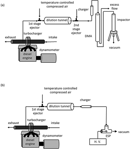
For particle collection, the diluted exhaust stream was sent to a differential mobility analyzer (DMA; TSI model 3081, Shoreview, MN; operating condition: sheath flow at 10 liter per minute [lpm] and sample flow at 1 lpm) and particles were size-selected at 150 nm mobility diameter as shown in a. Following the DMA, a low pressure impactor (LPI) (CitationHering et al., 1979) collected a size-selected (150 nm) particle sample onto a transmission electron microscopy (TEM) grid placed in the center of the impactor plate similar to that described by CitationJung et al. (2004).
Case 2: Undoped combustion in a heavy-duty engine
The engine used in this experiment was a 1995 Caterpillar 3176 C-12 diesel engine designed for use in over the road trucks. The engine is reconfigured to meet the post–consent decree 1998 standards. It is an electronically controlled, direct-injection, 6-cylinder, 12-L, turbocharged, and aftercooled engine with a peak power of 265 kW. It was operated at 1200 rpm under 10% load (225 N·m) on an eddy current dynamometer. Standard EPA No. 2 (as of 2003 when the test was performed) on-road diesel fuel containing 300–500 ppm sulfur and SAE15W-40 (John Deere TY6391) engine lubrication oil was used. [Note: Current (as of 2013) standard EPA No. 2 on-road diesel fuel contains much less sulfur.] The diesel exhaust stream was sampled and diluted using a single-stage dilution tunnel and the dilution ratio was approximately 25:1. Particles in the diluted exhaust stream were collected on a TEM grid placed in a prototype electrostatic precipitator (ESP) with 2000 volts DC bias voltage (CitationMiller et al., 2010) as shown in Figure 1b. The voltage was supplied to the TEM grid placed at the tip of a high-voltage rod, which is insulated from other parts of the ESP by an insulator end cap.
Case 3: (Fe-)Doped combustion in a light-duty engine
The source of diesel particulate for this case was an Onan-Cummins Quiet Diesel genset powered by a 3-cylinder, 1.5-L Isuzu engine. This unit is capable of providing 10 kW of continuous AC (alternating current) power at a fuel flow rate of about 3 kg/hr. In order to maintain a steady 60 Hz of AC current from the generator, the fuel flow to the engine is controlled by an electronic governor actuator that maintains a constant engine speed of 1800 rpm. The load on the engine is provided by loading the generator outlet with a resistive load bank. For the purposes of this experiment, the engine was run at 60% load, i.e., with the generator producing 6 kW of power. The corresponding fuel flow rate was 2.25 kg/hr. The fuel used was standard EPA No. 2 on-road diesel fuel (300–500 ppm sulfur), doped with varying amounts of ferrocene, yielding a fuel mixture containing from 60 to 600 ppm iron by mass.
The diesel exhaust was diluted approximately 10:1 in a single-stage dilution tunnel akin to that depicted in a. The diluted exhaust was routed to an LPI, and the particles were collected onto a TEM grid placed at the center of the impactor plate on the final stage of the LPI (50 nm aerodynamic diameter cutoff), whereas the upper stages were greased to prevent the particle bouncing problem.
Results
Carbon nanotubes among diesel exhaust particles
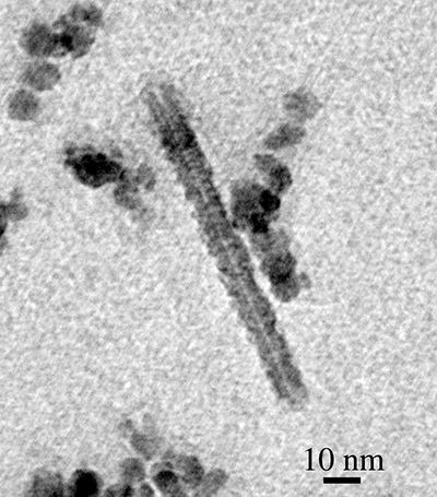
The TEM samples from all three tests were analyzed by electron microscopy to study particle size and morphology. During these analyses, CNTs were observed among diesel exhaust particles from all three of the tests. shows a well-distinguishable nanotube obtained from the case 1 (undoped) experiment. The tube has approximately 20 nm outer diameter, 2 nm inner diameter, and is 150 nm in length. It is observed that the tube was attached to or extruded from a large (assumedly carbonaceous) cluster. The dark spot in the center of the image is thought to be a possible candidate for a catalyst particle, but elemental analysis (such as energy dispersive X-ray spectroscopy [EDS]) was not done at the time the image was taken. For case 1, a JEOL 1210 TEM (Tokyo, Japan; accelerating voltage: 40 to ~120 kV, magnification: 50× to ~800,000×) was used to obtain TEM images. For cases 2 and 3, particles were imaged and photographed using a Philips CM12 TEM (FEI Company, Hillsboro, OR, USA) operating at 60 kV accelerating voltage and using TEM spot size settings of 2–5. Images were recorded on Kodak Electron Microscopy Film 4489 and developed in Kodak developer D-19 (Rochester, NY) at full strength for 3.0 min.
Figure 2. CNT collected from Deere engine T04045TF250 at 1400 rpm under 50% load (200 N·m) with undoped diesel fuel. The tube has ∼20 nm outer diameter, ∼2 nm inner diameter, 150 nm length.
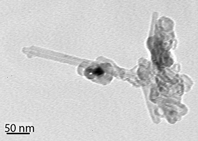
Particles with a similar morphology (i.e., tubes extruding from clusters) were also observed in the case 2 (undoped) experiment. Such a particle, obtained from the case 2 experiment, is seen in . Note the rod-shaped particles were attached to the soot agglomerate. The longest rods are approximately 173 nm in length with 14 nm outer diameter and 85 nm in length with 20 nm outer diameter, respectively. We could not positively identify whether these rods are nanotubes because a higher-resolution image was unavailable in the archived data. However, the brighter color of the rods compared with the dark color of the soot agglomerate indicates that the rods are less dense than soot, which suggests that they might be hollow tubes.
Figure 3. Rod-shaped particles attached at an agglomerate at the upper right of the image. Samples are collected from Caterpillar 3176 C-12 engine at 1200 rpm under 10% load (225 N·m) with undoped diesel fuel. No image is available in a bigger magnification to tell whether or not they are tubes. Each rod has 173 nm length, 14 nm outer diameter, and 85 nm length, 20 nm outer diameter, approximately and respectively.
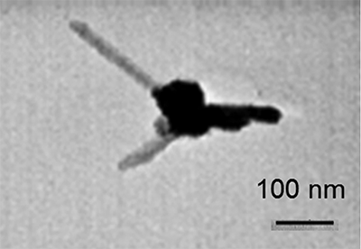
In the case 3 (doped) experiment, iron (in the form of ferrocene) was doped to the diesel fuel intentionally. Iron is a well-known catalyst used to form nanotubes in flame synthesis. shows a typical nanotube observed from the case 3 experiment using 600 ppm Fe doping of fuel. The tube has about an 8 nm outer diameter, a 0.8 nm inner diameter, and is about 90 nm in length. EDS analysis was conducted with the same type of nanotube as shown in . The beam size was slightly larger than the nanotube. Although a carbon peak was readily distinguishable after correcting for the background, there was no distinguishable peak of any important transition metals (Fe, Ni, Co) for nanotube formation. Considering the thickness of the wall, it is deduced to be a multiwalled nanotube. The carbon nanotubes and nanotube-like rods in this study were shown as individual particle, whereas nanofibers among diesel particles reported by CitationEvelyn et al. (2003) were shown as grouped nanofibers due to their sampling method using liquid extraction. Whereas the fraction of nanotubes or nanotube-like rods among other diesel particles was near zero in the undoped cases, nanotubes could be more easily found in the case 3 (doped) experiment and the frequency of occurrence was approximately 1% for that case. It is believed that this is the result of having a transition metal catalyst (Fe) available to form nanotubes, because it was supplied continuously in the fuel. That hypothesis is based on the demonstrated correlation between metallic nanoparticle formation and the metal-to-carbon ratio during diesel combustion (CitationMiller et al., 2007). However, more work is necessary to statistically correlate the increased number of CNTs with the level of Fe doping.
Possibility of contamination
CitationHarris (2001) reported fullerene-like structures such as nanotubes and nanoparticles from blank TEM grids. He explained that the arc-evaporation of graphite, which is used to make carbon film of the TEM grid, can lead to the formation of fullerene-like structures. He specifically reported poorly graphitized carbon, graphite platelet, clustered nanotubes, and embedded nanoparticles as examples of contaminants on TEM grid. He suggested that use of noncarbon film such as silicon oxide film can avoid such contaminants. CitationKlie et al. (2004) also reported specific examples of carbon contaminants on TEM and scanning electron microscopy (SEM) grids with carbon film. The example also shows clustered nanotubes as contaminants. And they were multiwalled nanotubes. Klie et al. (2004) concluded that it is difficult to distinguish real sample against contaminants if sample density on the grid is low. However, they concluded if the sample density is high, then chance of looking at contaminant nanotubes is low. In our study, we have used silicon monoxide film and carbon film TEM grid for case 1. The same batch of carbon film TEM grid was used for our other study to take aluminum particles. Although we have not preexamined out TEM grids, we have never observed any carbonaceous contaminants in our other study with aluminum particles when the same batch of carbon film TEM grid was used. For cases 2 and 3, we have used both Formvar film and carbon film TEM grids. As the sample density was low for the case 2, we cannot conclude whether what we observed in is a contaminant or real sample. However, the sample density for the case 3 was relatively higher than any other samples and all CNT-like structures were not clustered. Therefore, it is more likely that these are real samples not contaminants.
Source of catalytic metals
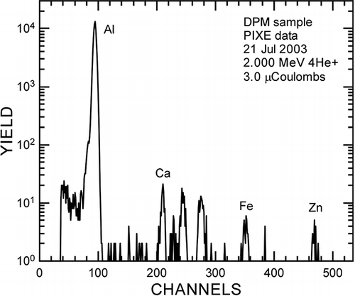
Even though there was an intriguing observation of carbon nanotubes in a diffusion flame without a metal catalyst (CitationMerchan-Merchan et al., 2002), it is widely accepted that catalytic particles play a key role in the growth process of CNTs. For the case of normal (undoped) diesel combustion, it is possible that the source of catalytic metals could be Fe from mechanical wear and/or metals derived from lube oil additives. CitationOkada et al. (2003) measured trace metal composition in diesel exhaust particles using inductively coupled plasma-mass spectroscopy (ICP-MS). In that work, the presence of Fe, assumedly coming from mechanical wear, showed the second highest emissions relative to other metal compounds. This result was confirmed by the results of baseline (undoped) data taken during the case 3 experiment. For that baseline work, even though no Fe doping was used, Fe was measured in diesel particle samples (see ) using particle-induced X-ray emissions (PIXE). If one argues that this Fe derives from engine wear, and it is likely carried by the lube oil. The metals involved in normal diesel combustion also include those from lube oil additives. shows the metal content of the lube oil used for the case 1 experiment. It is fairly typical that lube oil contains various metals, including a significant amount of Ca and Zn. Although it does not contain any 3d transition metal such as Fe, Ni, and Co, known to be important for CNT synthesis (CitationCheng et al., 1998; CitationVander Wal et al., 2003), we do not exclude the possibility of metals from lube oil playing a role as catalysts to form nanotubes. It is notable that other researchers have synthesized single-walled CNTs from diesel particles (CitationUchida et al., 2006). For that work, diesel particles were collected from a genset and a marine diesel. The particles were subsequently mixed with Co and Ni and the mixture was ablated with a laser to make single-walled CNTs. Interestingly, they tried but did not succeed in making CNTs using other similar carbonaceous particles such as activated carbon (Darco G-60) or acetylene carbon black. They reported that C60, C70, and other fullerene structures were contained in the diesel soot, thought to be formed during combustion of light or heavy oil. It was postulated that those structures may have contributed to the CNT formation when the soot was ablated with a catalyst. CitationLagally et al. (2012) reported the presence of CNTs and fullerene from 2- and 4-stroke spark-ignited engines. The Indian Autorickshaw engines are not necessarily operated like modern stoichiometry gasoline engine and that might have provided fuel-rich conditions for the formation of CNTs. CitationMurr et al. (2006) found CNTs among ambient aerosol in El Paso, Texas, implying the importance of controlling emissions of nanomaterials, including nanotubes.
Table 1. Metal contents of lube oil
Conclusion
Carbon nanotubes are known to form under very specific conditions in a flame environment (CitationHeight et al., 2004), even without a metallic catalyst. It therefore deserves attention that the diesel combustion process has the potential to generate CNTs with both doped and undoped fuel. Although the fraction of CNTs among other diesel particles is very low, especially when using undoped diesel fuel, the potential adverse health effects of airborne CNTs warrants further investigation into this phenomenon. Our observation is somewhat similar with that of CitationEvelyn et al. (2003) who reported carbon nanofibers and chains among diesel particles and CitationLagally et al. (2012) who reported CNTs from spark-ignited engines. It is likely that Fe from mechanical wear and the metal additive package from lube oil may play a role as catalysts to form such nanotubes.
Increased attention is being given to CNTs and other nanomaterials and a review paper showed that CNTs are capable of inflammation in the lung when inhaled (CitationLam, 2006). Furthermore, iron-containing compounds are used as a fuel-borne catalyst for diesel in Europe (CitationKasper et al., 1999; CitationSkillas et al., 2000) and as an antiknock additive in some countries (CitationGidney et al., 2010), increasing the possibility of producing CNTs during internal combustion. For this reason and because diesel engines are so common, it is important to acknowledge the existence of CNTs among diesel particles and further work should be done to better understand their origin and prevalence in diesel emissions.
Acknowledgment
Kihong Park acknowledges support from the National Research Foundation of Korea (NRF) (grant 2011-0015548) on this work.
References
- Abdul-Khalek , I. , Kittelson , D.B. and Brear , F. 1999 . The Influence of Dilution Conditions on Diesel Exhaust Particle Size Distribution Measurements , SAE Technical Paper Series 1999-01-1142 . doi: 10.4271/1999-01-1142
- Cheng , H.M. Li , F. 1998 . Large-scale and low-cost synthesis of single-walled carbon nanotubes by the catalytic pyrolysis of hydrocarbons . Appl. Phys. Lett , 72 : 3282–3284 doi: 10.1063/1.121624
- Evelyn , A. Mannick , S. 2003 . Unusual carbon-based nanofibers and chains among diesel-emitted particles . Nano Lett , 3 : 63 – 64 . doi: 10.1021/nl025803u
- Gidney , J.T. , Twigg , M.V. and Kittelson , D.B. 2010 . Effect of organometallic fuel additives on nanoparticle emissions from a gasoline passenger car . Environ. Sci. Technol , 44 : 2562 – 2569 . doi: 10.1021/es901868c
- Hafner , J.H. Bronikowski , M.J. 1998 . Catalytic growth of single-wall carbon nanotubes from metal particles . Chem. Phys. Lett , 296 : 195 – 202 . doi: 10.1016/S0009-2614(98)01024-0
- Harris , P.J.F. 2001 . Carbonaceous contaminants on support films for transmission electron microscopy . Carbon , 39 : 909 – 913 . doi: 10.1016/S0008-6223(00)00195-0
- Height , M.J. Howard , J.B. 2004 . Flame synthesis of single-walled carbon nanotubes . Carbon , 42 : 2295 – 307 . doi: 10.1016/j.carbon.2004.05.010
- Hering , S.V. , Friedlander , S.K. , Collins , J.J. and Richard , L.W. 1979 . Design and evaluation of a new low-pressure impactor. 2 . Environ. Sci. Technol , 13 : 184 – 188 . doi: 10.1021/es60150a009
- Journet , C. Maser , W.K. 1997 . Large-scale production of single-walled carbon nanotubes by electric-arc technique . Nature , 388 : 756 – 758 . doi: 10.1038/41972
- Jung , H. , Kittelson , D.B. and Zachariah , M.R. 2004 . Kinetics and visualization of soot oxidation using transmission electron microscopy . Combust. Flame , 136 : 445 – 456 . doi: 10.1016/j.combustflame.2003.10.013
- Kasper , M. , Sattler , K. , Siegmann , K. , Matter , U. and Siegmann , H.C. 1999 . The influence of fuel additives on the formation of carbon during combustion . J. Aerosol Sci , 30 : 217–225 doi: 10.1016/S0021-8502(98)00034-2
- Klie , R.F. , Ciuparu , D. , Pfefferle , L. and Zhu , Y. 2004 . Multi-walled carbon nanotubes on amorphous carbon films . Carbon , 42 : 1953 – 1957 . doi: 10.1016/j.carbon.2004.03.029
- Lagally , C.D. , Reynolds , C.C.O. , Grieshop , A.P. , Kandlikar , M. and Rogak , S.N. 2012 . Carbon nanotube and fullerene emissions from spark-ignited engines . Aerosol Sci. Technol , 46 : 156 – 164 . doi: 10.1080/02786826.2011.617399
- Lam , C.-W.J. , John , T. , McCluskey , R. , Arepalli , S. and Hunter , R.L. 2006 . A review of carbon nanotube toxicity and assessment of potential occupational and environmental health risks . Crit. Rev. Toxicol , 36 : 189 – 217 . doi: 10.1080/10408440600570233
- Merchan-Merchan , W. Saveliev , A. 2002 . Formation of carbon nanotubes in counter-flow, oxy-methane diffusion flames without catalysts . Chem. Phys. Lett , 354 : 20 – 24 . doi: 10.1016/S0009-2614(02)00027-1
- Miller , A. Ahlstrand , G. 2007 . The fate of metal (Fe) during diesel combustion: Morphology, chemistry, and formation pathways of nanoparticles . Combust Flame , 149 : 129 – 143 . doi: 10.1016/j.combustflame.2006.12.005
- Miller , A.L. , Frey , G. , King , G. and Sunderman , C. 2010 . A handheld electrostatic precipitator for sampling airborne particles and nanoparticles . Aerosol Sci. Technol , 44 : 417 – 427 . doi: 10.1080/02786821003692063
- Miller , A.L. Stipe , C. 2007 . Role of lubrication oil in particulate emissions from a hydrogen-powered internal combustion engine . Environ. Sci. Technol , 41 : 6828 – 6835 . doi: 10.1021/es070999r
- Murr , L. E. Soto , K.F. 2006 . Combustion-generated nanoparticulates in the El Paso, TX, USA/Juarez, Mexico metroplex: Their comparative characterization and potential for adverse health effects . Int. J. Environ. Res. Public Health , 3 : 48 – 66 . doi: 10.3390/ijerph2006030007
- Nikolaev , P. 2004 . Gas-phase production of single-walled carbon nanotubes from carbon monoxide: A review of the HiPco process . J. Nanosci. Nanotechnol , 4 : 307 – 316 . doi: 10.1166/jnn.2004.066
- Okada , S. Kweon , C.-B. 2003 . Measurement of Trace Metal Compostion in Diesel Engine Particulate and Its Potential for Determining Oil Consumption , SAE Technical Paper Series 2003-01-0076 . doi: 10.4271/2003-01-0076
- Porter , D. W. Hubbs , A.F. 2010 . Mouse pulmonary dose- and time course-responses induced by exposure to multi-walled carbon nanotubes . Toxicology , 269 ( 2–3 ) : 136 – 147 .
- Sen , S. and Puri , I.K. 2004 . Flame synthesis of carbon nanofibres and nanofibre composites containing encapsulated metal particles . Nanotechnology , 15 : 264 – 268 . doi: 10.1088/0957-4484/15/3/005
- Skillas , G. , Qian , Z. , Baltensperger , U. , Matter , U. and Burtscher , H. 2000 . The influence of additives on the size distribution and composition of particles produced by diesel engines . Combust. Sci , 154 : 259 – 273 . doi: 10.1080/00102200008947279
- Su , M. Zheng , B. 2000 . A scalable CVD method for the synthesis of single-walled carbon nanotubes with high catalyst productivity . Chem. Phys. Lett , 322 : 321 – 326 . doi: 10.1016/S0009-2614(00)00422-X
- Thess , A. Lee , R. 1996 . Crystalline rope of metallic carbon nanotubes . Science , 273 : 483 – 487 . doi: 10.1126/science.273.5274.483
- Uchida , T. Ohashi , O. 2006 . Synthesis of single-wall carbon nanotubes from diesel soot . Japn. J. Appl. Phys. Part 1 , 45 ( 10A ) : 8027 – 8029 . doi: 10.1143/JJAP.45.8027
- Vander Wal , R. 2002 . Fe-catalyzed single-walled carbon nanotube synthesis within a flame environment . Combust. Flame , 130 : 37 – 47 . doi: 10.1016/S0010-2180(02)00360-7
- Vander Wal , R. Berger , G.M. 2003 . Carbon nanotube synthesis in a flame with independently prepared laser-ablated catalyst particles . J. Nanosci. Nanotechnol , 3 : 241 – 245 . doi: 10.1166/jnn.2003.201
- Yuan , L. Saito , K. 2001 . Ethylene flame synthesis of well-aligned multi-walled carbon nanotubes . Chem. Phys. Lett , 346 : 23 – 28 . doi: 10.1016/S0009-2614(01)00959-9
