Abstract
This work was focused on the enhanced photocatalytic activity of cobalt phthalocyanine (CoPc)/TiO2 under visible light irradiation supported on reduced graphene oxide (RGO). A series of RGO/CoPc/TiO2 nanocomposites were synthesized via sol-gel–hydrothermal method. The photocatalysts were characterized by X-ray diffraction, BET surface area, Scanning electron microscopy, Raman spectra, Fourier transform infrared spectra, UV–Vis spectra and Photoluminescence spectra. The results demonstrated that the TiO2 existed as anatase phase both of CoPc/TiO2 and RGO/CoPc/TiO2 composites, and the absorption range in visible light of RGO/CoPc/TiO2 composites were broadened further. The photodegradation results of diethyl sulfide, the typical gas of landfill exhaust, under visible light revealed that RGO/CoPc/TiO2 nanocomposites exhibited much higher photocatalytic activity than CoPc/TiO2 and pure TiO2, indicating the ideal amount of RGO was 7.5wt.%, the optimal amount of 7.5% RGO/CoPc/TiO2 composite on each plat was 0.3g and the degradation efficiency of diethyl sulfide was about 90%.
Implications: Over the past decades, air pollution has become more and more serious, many countries have reported that the complaints of odor problems related to urban garbage and industry are increasing. This study is beneficial for the exhaust governance of some landfills. Moreover, the process doesn’t involve any expensive oxidizing chemicals and can be performed under normal conditions of temperature and pressure.
Introduction
With the rapid development of industry and urbanization, odor pollutions are harming both the environment and human health (Li et al., Citation2012). As one typical source of odor pollution, the fetor pollution from urban garbage has attracted increasing attention (Rappert et al., Citation2005; Mao et al., Citation2006; Landaud et al., Citation2008; Wu et al., Citation2010). In the process of the landfill or disposal of garbage, plenty of strong smell and irritating gaseous metabolites or intermediate products will be produced, including organic sulfur, inorganic sulfur, fatty acid, amine, terpenoid substances, and other volatile organic compounds (Ding et al., Citation2012).
The treatment of odor pollution is imperative (Bergersen et al., Citation2008, Citation2014). Photocatalysis applied to remove odor pollutants has many advantages, such as low cost, operating easily, and so on (Ai et al., Citation2011; Yu et al., Citation2013). TiO2 has been widely known as photocatalytic material due to its high catalytic efficiency, chemical stability, and low cost (Chen et al., Citation2007; Tian et al., Citation2010). However, the forbidden bandwidth of TiO2 is so large (Eg ≈ 3.0–3.2 eV) that its absorption spectrum is in the near ultraviolet (UV) region (λ < 400 nm). The application of nano TiO2 coating has a certain scale, but UV lamp is mainly used as the excitation light source in the process of photocatalysis (Zacarías et al., Citation2012). It is urgent to solve the problem of realizing the visible light response of TiO2. Previous studies have reported that doping modification and sensitization of catalyst’s surface were effective ways to solve the problem (Liu et al., Citation1999; Ranjit et al., Citation1998). In addition, phthalocyanine cobalt (CoPc) has been widely used in oil desulfurization as catalyst (Schippera et al., Citation1994). After compositing CoPc and TiO2 together effectively, CoPc will be excited under visible light and send electrons to the conduction band of TiO2. Then, the photoelectric conversion efficiency and photocatalytic efficiency of TiO2 will be improved, as the absorption wavelength range of TiO2 is broadened (Schubert et al., Citation1997; Stuchinskaya et al., Citation1999).
For the high surface area, carbon nanomaterials such as graphene (GR) are typically used as support for catalysts (Ghasemi et al., Citation2012). Moreover, graphene has an excellent charge carrier mobility at room temperature (≈200,000 cm2 V−1 sec−1) with a single layer two-dimensional graphite structure (Akhavan et al., Citation2009; Wang et al., Citation2012). The addition of GR can increase the surface area of TiO2 to trap more pollutants and enhances the catalytic properties of nanocomposites (Gu et al., Citation2013; Stengl et al., Citation2011). In addition, the introduction of GR can improve the photocatalytic activity of TiO2 because of the promotion of charge separation and stabilization (Perera et al., Citation2012; Jiang et al., Citation2011). Graphene-supported TiO2 photocatalysts have attracted increasing attention because of their excellent photocatalytic performance on the governance of environment (Li et al., Citation2013; Sher Shah et al., Citation2012). In order to enhance the catalytic performance of catalyst further, GR can be introduced into CoPc/TiO2 composite.
In this study, we synthesized RGO/CoPc/TiO2 and CoPc/TiO2 nanocomposites via sol-gel–hydrothermal method focused on the enhanced photocatalytic activity of CoPc/TiO2 under visible light irradiation. As shown in previous reports, pure TiO2 or sensitized with dye was mainly applied to the removal of pollutants in water solution (Liu et al., Citation2010; Palmisano et al., Citation2008; Enriquez et al., Citation2006; Agrios et al., Citation2006; Enriquez et al., Citation2007). Moreover, several studies on the application of TiO2 coating to control bacteria were published (Josset et al., Citation2007, Citation2008; Pal et al., Citation2008; Paschoalino et al., Citation2008). In this paper, the CoPc/TiO2 and RGO/CoPc/TiO2 modified coatings were applied to treat odorous pollutant with a continuous gas flow reactor. In the previous work, our team has conducted a comprehensive study of odorous gases in the pretreatment workshop of a landfill in Beijing, indicating that the landfill exhausts were mainly composed of aromatics, sulfur compounds, and nitrogenous compounds, and the concentrations of total chemical composition ranged from 19.7 to 24.2 mg·m−3 (Di et al., Citation2013). The analysis of odor activity value identified the top three compounds to be hydrogen sulfide (91.8), diethyl sulfide (35.8), and trimethylamine (70.6), which contributed to the odor pollution (Di et al., Citation2013). Based on the reports of references, the measurements of the composition of landfill gas indicated that the main chemical composition of odor gases were reduced sulfur compounds, the concentrations of which ranged from 1.8 to 1500 mg·m−3 (Kim et al., Citation2005). Therefore, in this paper, diethyl sulfide (CH3CH2SCH2CH3) was selected as the typical target odorous pollutant to inspect the catalytic effect of CoPc/TiO2 and RGO/CoPc/TiO2 coatings under visible light. This process doesn’t involve any expensive oxidizing chemicals and can be performed under normal conditions of temperature and pressure. Moreover, this study would provide basic guidelines for the governance of the odor pollution of landfill exhausts.
Experimental
Materials and instruments
Materials
Graphite flake (325 mesh, ≥99.8%) was purchased from Alfa Aesar (MA, USA). Butyl titanate (chemically pure [CP]) was purchased from Tianjin Guangfu Fine Chemical Co., Ltd. (Tianjin, China). CoPc (≥85.2%) was obtained from Nantong Zhenxin Pigment Co., Ltd. (Jiangsu, China). N,N-dimethylformamide (DMF) (analytical reagent [AR]) was purchased from Tianjin Yongda Chemical Reagent Co., Ltd. (Tianjin, China). Potassium permanganate (CP) was purchased from Beijing Chemical Reagent Company (Beijing, China). Sodium nitrate (AR), sulfuric acid (AR), and hydrogen peroxide (30%) were obtained from Sinopharm Chemical Reagent Co., Ltd. (Beijing, China). Ethanol (AR), acetic acid (AR), and hydrochloric acid (AR) were purchased from Beijing Chemical Works (Beijing, China). Ultrapure water was prepared using a Milli-Q apparatus (Millipore, Bedford, MA, USA).
Photocatalytic instruments
The atmospheric sampling instrument (QC-3; Beijing Municipal Institute Of Labour Protection) was used to pump gas into the photocatalytic device. Three fluorescent lamps (19 W; Panasonic, Japan) were used as visible light source, the irradiated light intensity was 1.064 mW/cm2 and the range of wavelength was 400–650 nm (three major wavelengths were 435, 545, and 610 nm). The solid-phase microextraction (SPME) (75 μm Carboxen/polydimethylsiloxane [CAR/PDMS]; Supelco, Bellefonte, PA, USA) was used for sampling. Gas chromatography (GC-2014; Shimadzu, Japan) was applied to analyze the concentration of diethyl sulfide.
Synthesis of catalysts
Preparation of graphene oxide (GO)
GO was synthesized using a modified Hummers’ method (Cote et al., Citation2009; Zhao et al., Citation2010). Typically, 1 g natural graphite flake was reacted with 1 g NaNO3, 48 mL concentrated H2SO4, and 6 g KMnO4, then 5 mL H2O2 (30%) was added to the mixture after completion of the reaction. After the precipitate was washed and centrifuged with dilute HCl (5%) and deionized water several times until all visible particles were removed, it was dried in an oven at 60 °C for 12 hr.
Synthesis of RGO/CoPc/TiO2 nanocomposites
TiO2 composited with CoPc and different mass ratios of GO hybrids were synthesized via sol-gel–hydrothermal method. Firstly, 0.2, 0.3, and 0.4 g GO were sonicated in 20 mL ethanol for 3 hr to achieve uniform dispersions of GO. Next, 17 mL butyl titanate, 34 mL ethanol, and 4.8 mL acetic acid were added to the GO dispersions while stirring. After stirring at room temperature for 1 hr, 0.03 g CoPc and 5 mL DMF were added to the mixture. Continuing to stir for 1 hr, 2 mL ultrapure water was added to the mixture. Then, the gel was poured into the 100-mL reaction kettle, and the temperature was held at 160 °C for 16 hr. Excess water was removed, and the solid was washed with deionized water two times and ethanol two times. Finally, the product was dried in an oven at 60 °C for 2.5 hr. The initial mass ratios of GO to RGO/CoPc/TiO2 were calculated to be 5%, 7.5%, and 10%, and the products were denoted as 5% RGO/CoPc/TiO2, 7.5% RGO/CoPc/TiO2, and 10% RGO/CoPc/TiO2. For comparison, CoPc/TiO2 was prepared using a similar sol-gel–hydrothermal procedure without GO and pure TiO2 was obtained without either GO or CoPc.
Preparation of catalyst coatings
Before coating, six pieces of glass plates (15 cm × 29 cm), one side of which were frosted, were cleaned with ethanol and deionized water and then dried in an oven at 50 °C. Six portions of the suspension of 0.5 g catalyst powder in 10 mL deionized water were magnetically stirred initially and then uniformly brushed onto each frosted side of the glass plates (Wei et al., Citation2014). Then, the coating plates were dried at 30 °C for 30 min. A series of RGO/CoPc/TiO2 coatings, CoPc/TiO2 coating, and TiO2 coating were prepared with this method. The coatings obtained with this method could withstand the gas flow, and the amount of catalyst powder peeled off from the glass plate was less than 1 wt.% after experiments (Josset et al., Citation2007). After a series of photocatalytic tests of different catalysts, 7.5 wt.% RGO/CoPc/TiO2 composite was selected to test the effect of the amount. Six pieces of coatings of 0.1 g catalyst powder on each plate were prepared with the method above, and six pieces of coatings of 0.3 g catalyst powder were prepared with the same steps.
Characterization
X-ray diffraction (XRD) studies were performed by X-ray diffractometer (D/MAX-RB; Rigaku, Japan), and the grain sizes were obtained by the calculation of Schrerrer formula. Specific surface areas were measured using the Brunauer-Emmett-Teller (BET) method (NOVA 4200e; Quantachrome, USA). The morphology of samples was recorded by scanning electron microscopy (SEM) (Ultra; Zeiss, Germany), and the enlargement factor was 5000×. Raman spectra were collected using a JY Horiba HR800 spectrophotometer (France) in the backscattering geometry with a 532-nm semiconductor laser as the excitation source. Infrared (IR) spectra were recorded by Fourier transform infrared spectrometer (Nexus 670; Nicolet, USA) with KBr compression; ultraviolet-visible (UV-Vis) spectra were recorded by UV-Vis instrument (TU-1901; Purkinje General, China), and the range of scanning wavelength was 250–800 nm. Photoluminescence (PL) spectra were determined by photoluminescence spectrometer (F-4500; Hitachi, Japan), and the excitation wavelength was 350 nm.
Photocatalytic experiments
Photocatalysis experiments were carried out in a gas flow model. shows the schematic diagram of the continuous photocatalytic system. The photocatalytic device was made of Plexiglas, and the volume was 54 L (120 cm ×15 cm × 30 cm). In order to avoid the interference of outside light, the chamber was covered with aluminum foil. To guard against leakage, a layer of silicone rubber was covered on the contact surface between top cover and cabin and then fastened with bolts around. There were six pieces of partitions inside the cabin, and card troughs were designed on the both sides of partitions to fix the catalyst coatings. In order to guide the direction of gas flow, a gap of 1 cm width was set between partition and top or bottom alternately, extending the flow path of gas. Between the two partitions there was a fluorescent lamp used as visible light source. In addition, the most optimal number of lamps and catalyst coatings were three and six, respectively, after a series of tests. At two ends of the cabin, there were two pieces of pipe with 1.5 cm diameter and two sampling points were at the fixed position of the two pipes, used as the sampling point to sample the mixed gas before entering the device and the exhaust gas after photocatalytic treatment using the SPME, respectively. After sampling for 15 min, the fibers of the SPME was inserted into the injection port of the gas chromatograph (GC) for analysis. Target gas (diethyl sulfide) and the air in the room were pumped through a piece of pipe into the device by an atmospheric sampling instrument at the flow rates of 0.1 and 0.5 L·min−1, respectively, and the concentrations of the mixed gas was about 40 mg·m−3.
Figure 1. Gas flow model for photocatalysis experiments (1 = target gas; 2 = air; 3, 8 = sampling points; 4 = bolt; 5 = partition; 6 = card trough; 7 = light source).
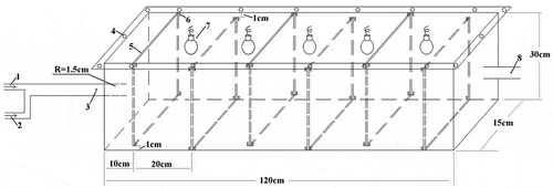
Six pieces of catalyst coatings were placed inside the device and fixed, and then the bolts were fastened. After pumping the mixed gas into the device for 2.5 hr in the dark, the three fluorescent lamps were turned on; according to the result of three times of blank experiments indicating the concentration of diethyl sulfide at the two sampling points 3 and 8 (as shown in ) would be the same after 2.5 hr, it was ensured the air in the device was fully discharged. Then, the concentrations of diethyl sulfide at the two sampling points 3 and 8 (as shown in ) were determined every half an hour. The efficiency of the degradation of diethyl sulfide was calculated as eq 1:
Quality control and assurance
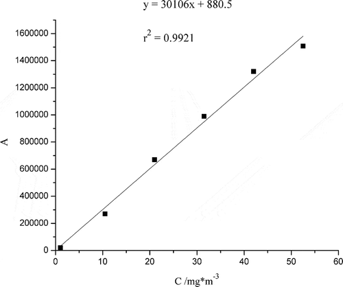
The peak area of diethyl sulfide was measured by gas chromatograph (GC)equipped with flame ionization detector (FID). Rtx-5 chromatographic column (30 m × 0.25 mm; 0.25 μm) was used as separation column, and the column temperature was 200 °C. N2 was used as carrier gas, and the split ratio was 1:10. The detection limit was measured by three parallel analyses to be 0.04 mg·m−3, with a signal/noise ratio of 3 (Dincer et al., Citation2006). The calibration curve of peak area (A) and the concentration (C) of diethyl sulfide was drawn with this method, as shown in . Moreover, the concentrations of diethyl sulfide were determined with the curve. The precision of this method was estimated with the relative standard deviation (RSD) values of six parallel tests of standard sample and was found to be 3.3%. Moreover, the RSD values of three replicate tests for each photocatalytic experiment were found to be in the range of 1.7–9.2% (Kim et al., Citation2005).
Results and Discussions
Characterization of GO and RGO/CoPc/TiO2 composites
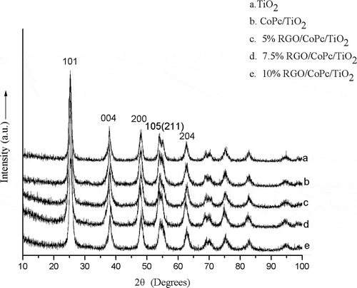
The crystalline phase of TiO2, CoPc/TiO2, and RGO/CoPc/TiO2 composites was characterized by XRD measurements (). The results showed that pure TiO2, CoPc/TiO2, and RGO/CoPc/TiO2 composites all existed in the pure anatase phase, with six characteristic diffractions at 25.3° (101), 37.9° (004), 48° (200), 54.1° (105), 55.1° (211), and 62.7° (204) (Joint Committee on Powder Diffraction Standards [JCPDS] 21-1272). As shown in the XRD patterns of RGO/CoPc/TiO2 composites, no obvious (002) diffraction peak of GO at ~10.5° was observed and (002) diffraction peak of RGO located at ~25° couldn’t be distinguished from the (101) peak of TiO2 at 25.3° (Perera et al., Citation2012). In order to avoid the influence of overlapping diffraction peaks, the average crystal sizes of the RGO/CoPc/TiO2 composites calculated with (200) peak of TiO2 using Scherrer equation were in the range of 7.2−8.1 nm, which is smaller than TiO2 (9.1 nm) but bigger than CoPc/TiO2 (6.7 nm). Compared with TiO2, the particle size of CoPc/TiO2 decreased, which illustrated that CoPc hindered TiO2 particles to get bigger and affected the rate of particle growth to slow down. In addition, the introduction of RGO also affected the crystal growth of TiO2.
The results of BET specific area of the photocatalysts (150.9 m2 g−1 for pure TiO2, 164.4 m2 g−1 for CoPc/TiO2, and 156.0, 172.6, 163.2 m2 g−1 for RGO/CoPc/TiO2 composites) indicated that the addition of CoPc enlarged the specific area, but the introduction of RGO couldn’t always enlarge the specific area for the reason that the addition of a small amount of RGO caused the aggregation of particles. Moreover, when the RGO loading was further increased from 7.5% to 10%, the BET specific area decreased because of the aggregation of RGO sheets (Li et al., Citation2013). The consequence was consistent with the analysis of particle size; the decrease of particle size and the enlargement of the specific area both could improve the photocatalytic activity of photocatalysts.
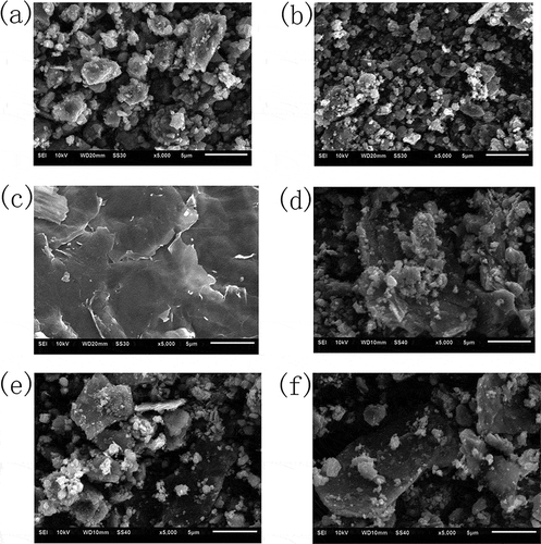
As shown in and , compared with pure TiO2, the particles of CoPc/TiO2 composite dispersed evenly and the polymerization degree reduced, indicating that the addition of CoPc had an effect on the growth of nanoparticles. showed the SEM image of GO, demonstrating that the surface morphology of GO was not completely flat but crumpled, which was in agreement with the reported (Gu et al., Citation2013). After the treatment of ultrasonic dispersion and the sol-gel–hydrothermal reaction, the block materials with the thickness of about 0.5 μm were RGO/CoPc/TiO2 composites and the particles of CoPc/TiO2 were attached on the surface of RGO, as shown in , , and f.
Figure 4. SEM images of (a) TiO2, (b) CoPc/TiO2 composite, (c) GO, (d) 5% RGO/CoPc/TiO2 composite, (e) 7.5% RGO/CoPc/TiO2 composite, and (f) 10% RGO/CoPc/TiO2 composite.
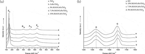
Raman spectroscopy can provide the information on the structure of TiO2 and confirm the successful oxidation of natural graphite and the combination with CoPc/TiO2. As shown in , the four Raman scattering peaks at 144 cm−1 (Eg), 397 cm−1 (B1g), 516 cm−1 (A1g), and 639 cm−1 (Eg) derived from anatase TiO2. After composited with CoPc and RGO, the four characteristic peaks of anatase TiO2 still existed. The Raman scattering peaks of Eg shifted and broadened in the composites of CoPc/TiO2 and RGO/CoPc/TiO2, such as the stronger peak blue-shifted from 144 to 148 and 150 cm−1. As shown in , the Raman spectra of GO showed two peaks of D band (1342 cm−1) and G band (1590 cm−1). The D band, from the sp3 hybridization of carbon atoms, reflected the internal structural defects of graphite, and the G band, from the sp2 hybridization of carbon atoms, indicated the symmetry plane stretching of C–C. Therefore, the Raman spectrum of GO illustrated that the natural graphite was oxidized to GO with the improved Hummers’ method. For RGO/CoPc/TiO2 composites, the characteristic peaks of D band and G band still existed in the range of 1200–1800 cm−1. Compared with GO, the strength of the D/G intensity ratio (ID/IG) of RGO/CoPc/TiO2 composites increased from 1.14 to 1.41, 1.30, and 1.37, respectively, which showed that the lattice symmetry of graphite was broken after the reduction of GO, the average crystallite size and the number of graphene layers decreased. In addition, the peak of G band blue-shifted to 1596 cm−1. The increase of ID/IG and the blue shift of peak proved the presence of graphene in the RGO/CoPc/TiO2 composites, as well as the chemical actions among CoPc, TiO2, and graphene.
Figure 5. (a) Raman spectra of TiO2, CoPc/TiO2, and RGO/CoPc/TiO2 composites. (b) Raman spectra of characteristic D and G bands of GO and RGO/CoPc/TiO2 composites.
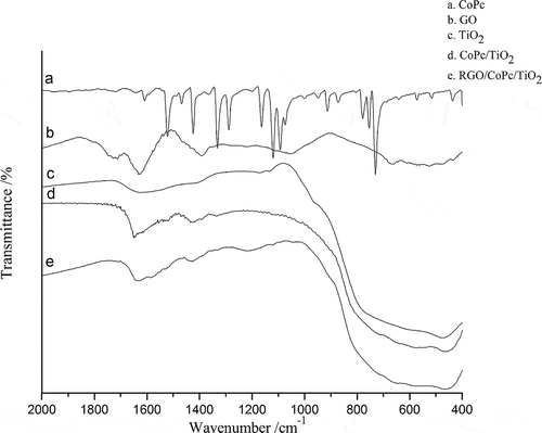
As shown in , in the Fourier transform infrared (FT-IR) spectrum of GO the peak at 1720 cm−1 was related to C=O stretching vibration of COOH, the peak at 1628 cm−1 was assigned to the carbon skeleton vibration of unoxidized graphite, the peak at 1395 cm−1 was related to O–H deformation vibration, and the peak at 1052 cm−1 was assigned to C–O stretching vibration (Gu et al., Citation2013). Combined with the Raman spectrum of GO, the natural graphite was further confirmed to be oxidized successfully. In the spectrum of TiO2, the strong peak located at 471 cm−1 was assigned to Ti–O–Ti stretching vibration. For CoPc/TiO2 and RGO/CoPc/TiO2 composites, the peak of Ti–O–Ti stretching vibration red-shifted to 460 cm−1, indicating that chemical action was formed between the interface of CoPc and TiO2 in the composites. In the IR spectra of CoPc/TiO2 and RGO/CoPc/TiO2, the peaks at 1425 cm−1 was related to C–C stretching vibrations of CoPc (Yang et al., Citation2014). The peak at 1610 cm−1 was the characteristic absorption peak of C–N stretching vibrations of phthalocyanine ring and blue-shifted in the composites of CoPc/TiO2 and RGO/CoPc/TiO2. In the IR spectra of RGO/CoPc/TiO2 composites, the characteristic peaks of GO didn’t exist, indicating the decomposition of oxygen-containing groups and that GO was reduced to be RGO (Low et al., Citation2013). Compared with CoPc/TiO2, in the IR spectra of RGO/CoPc/TiO2 composites new peaks at 1205 cm−1 appeared, which proved that some chemical actions were formed between RGO and CoPc/TiO2. In the range of 400–2000 cm−1, the IR spectra of CoPc/TiO2 and RGO/CoPc/TiO2 were broadly similar, showing the addition of graphene didn’t change the combining way between CoPc and TiO2. Thus, the characteristic peaks of CoPc and TiO2 both existed in the IR spectra of RGO/CoPc/TiO2 composites, and the change of characteristic absorption peaks and the emergence of new absorption peaks showed that CoPc, TiO2, and RGO composited successfully and a certain chemical effects were formed among them.
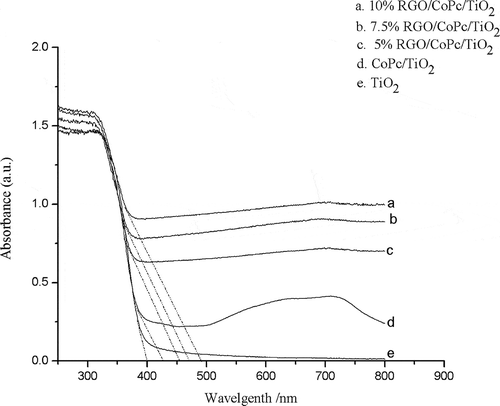
For photocatalysts, the band gap could affect photocatalytic activity and the absorption range of light played an important role, especially for the visible light (Low et al., Citation2013). As shown in , compared with pure TiO2, the absorption band of CoPc/TiO2 and RGO/CoPc/TiO2 composites had a red shift. There was a red shift of about 25 nm in the absorption edge of CoPc/TiO2 and 55–90 nm for RGO/CoPc/TiO2 composites when the graphene loading was increased from 5% to 10%, illustrating that the band gap energy was reduced in the CoPc/TiO2 and RGO/CoPc/TiO2 systems compared with pure TiO2 (Zhang et al., Citation2010; Lee et al., Citation2012). This finding was attributed to the efficiency of photocatalysis under visible light irradiation.
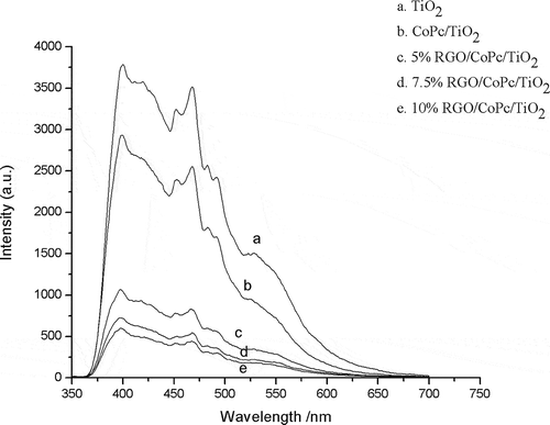
As shown in , the excitation spectrum of TiO2 was a wide excitation band and the emission peak was located at 400 and 470 nm, corresponding to the emission of free exciton and bound exciton caused by the oxygen vacancy or defects on the surface of TiO2 nanoparticles (Jing et al., Citation2004). The linear shapes of the PL spectra of CoPc/TiO2 and RGO/CoPc/TiO2 were similar to the pure TiO2, indicating that the addition of CoPc and RGO didn’t cause new fluorescent phenomenon. As the oxygen vacancy could bind electrons to form excitons and there were many oxygen vacancies on the surface of TiO2, the fluorescent effects of CoPc/TiO2 and RGO/CoPc/TiO2 composites were mainly caused by the nanometer crystallite surface structure of TiO2. The intensity of the fluorescence emission peak was mainly relevant to the efficiency of electron trapping and the recombination of electron and hole (Yu et al., Citation2002). Compared with pure TiO2, fluorescence quenching phenomenon appeared in the PL spectrum of CoPc/TiO2, illustrating the interaction and electron transfer between CoPc and TiO2. The stronger the quenching phenomenon, the easier electron transfer would be. With the introduction of RGO, a significant decrease in the emission intensity of the PL spectra of RGO/CoPc/TiO2 composites appeared and the degree of fluorescence quenching phenomenon increased when the graphene loading increased from 5% to 10%. The results indicated that the introduction of RGO could effectively prevent the recombination of electrons and holes in CoPc/TiO2 composite and further improved the efficiency of the separation of electrons and holes (Gu et al., Citation2013), which could further improve the photocatalytic activity of photocatalysts.
Photocatalytic tests
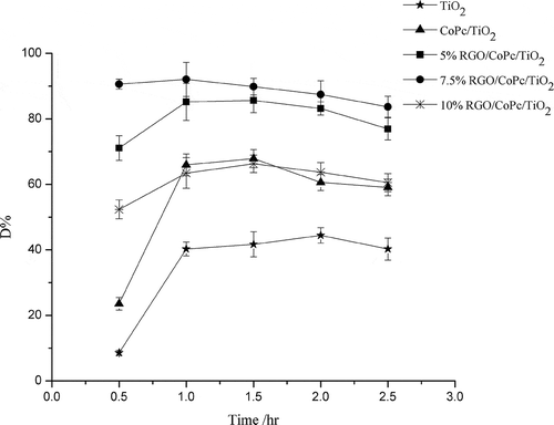
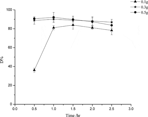
As shown in , compared with TiO2, the photocatalytic activity of CoPc/TiO2 was improved, for the reason that the absorption edge of CoPc/TiO2 red-shifted and its catalytic activity under visible light increased. The addition of RGO enhanced the photocatalytic activity further, with the comparison of effects of RGO loading on the photocatalytic activity of RGO/CoPc/TiO2 composites for degradation of diethyl sulfide indicating that the photocatalytic activities increased with increasing amount of RGO loading until a maximum was reached at 7.5% and the degradation efficiency was about 90%. The enhancement of photocatalytic activity resulted from the red shift of the absorption edge and the improvement of efficiency of the separation of electrons and holes. In addition, for the high surface area of RGO, the introduction of RGO increased the surface area of CoPc/TiO2 to trap more diethyl sulfide and then enhanced the catalytic properties of nanocomposites. As the catalytic efficiency of catalysts was decided by the combination of photocatalytic activity and surface area, and the catalytic efficiency was mainly decided by photocatalysis, the catalytic efficiency of 5% RGO/CoPc/TiO2 was higher than CoPc/TiO2, although the surface area of CoPc/TiO2 was larger. However, with increasing the proportion of RGO further, the photocatalytic activity decreased instead, because of the light-shielding effect of RGO: the excessive amount of RGO in the compound reduced the light arriving at the surface of the nanocomposite, resulting in the number of light excited electrons reduced and the catalytic efficiency was lower (Kim et al., Citation2012). As shown in , when the amount of 7.5% RGO/CoPc/TiO2 composite on each plate was 0.1 g, the catalytic efficiency was about 80%. The catalytic efficiency of 0.3 g was about the same as with 0.5 g and reached 90%.
Conclusion
In this paper, CoPc/TiO2 and a series of RGO/CoPc/TiO2 composites were synthesized via sol-gel–hydrothermal method and characterized by various techniques. Red shifts to the region of visible light were detected for CoPc/TiO2 and RGO/CoPc/TiO2 composites. The addition of RGO improved the photocatalytic activity of CoPc/TiO2. The high photocatalytic activity was attributed to higher surface area, lower electron-hole recombination rate, and narrower band gap. In addition, the higher photocatalytic activity determined that the optimal loading of RGO was 7.5% and the optimal amount of 7.5% RGO/CoPc/TiO2 composite on each plate was 0.3 g. This new control technology was designed for the preliminary exploration of the treatment of landfill exhausts, and there still existed many shortcomings. The performance of the catalyst such as persistence remained to be improved. Some factors possibly affecting the photocatalytic efficiency, such as humidity, temperature, and other impurities, would be taken into account according to the actual conditions of landfill environment and other compositions of landfill exhausts, such as nitrogenous compounds and aromatics, would be studied with the flow model. Therefore, much work remained to be continued for the treatment of landfill exhausts in future study.
Funding
This work was supported by the National High Technology Research and Development Program of China (2012AA030302), the National Natural Science foundation of China (20877008, 21277011), the Fundamental Research Funds for the Central Universities (FRF-TP-10-004B, FRF-BR-11-017B), and the Inter-project of Science and Technology New Star of Beijing City (XXHZ201207).
Additional information
Funding
Notes on contributors
Xiao-fen Fan
Jie-min Liu is a professor and Xiao-fen Fan is a student at the School of Chemistry and Biological Engineering, University of Science and Technology Beijing, Beijing, P.R. China.
Jie-min Liu
Jie-min Liu is a professor and Xiao-fen Fan is a student at the School of Chemistry and Biological Engineering, University of Science and Technology Beijing, Beijing, P.R. China.
References
- Agrios, A.G., and P. Pichat. 2006. Recombination rate of photogenerated charges versus surface area: Opposing effects of TiO2 sintering temperature on photocatalytic removal of phenol, anisole, and pyridine in water. J. Photochem. Photobiol. A Chem. 180:130–135. doi:10.1016/j.jphotochem.2005.10.003
- Ai, Z., L. Zhu, S. Lee, and L. Zhang. 2011. NO treated TiO2 as an efficient visible light photocatalyst for NO removal. J. Hazard. Mater. 192:361–367. doi:10.1016/j.jhazmat.2011.05.033
- Akhavan, O., and E. Ghaderi. 2009. Photocatalytic reduction of graphene oxide nanosheetson TiO2 thin film for photoinactivation of bacteria in solar light irradiation. J. Phys. Chem. C 113:20214–20220. doi:10.1021/jp906325q
- Bergersen, O., and K. Haarstad. 2008. Metal oxides remove hydrogen sulfide from landfill gas produced from waste mixed with plaster board under wet conditions. J. Air Waste Manage. Assoc. 58:1014–1021. doi:10.3155/1047-3289.58.8.1014
- Bergersen, O., and K. Haarstad. 2014. Treating landfill gas hydrogen sulphide with mineral wool waste (MWW) and rod mill waste (RMW). Waste Manage. 34:141–147. doi:10.1016/j.wasman.2013.09.012
- Chen, X., and S.S. Mao. 2007. Titanium dioxide nanomaterials: synthesis, properties, modifications, and applications. Chem. Rev. 107:2891–2959. doi:10.1021/cr0500535
- Cote, L.J., F. Kim, and J.X. Huang. 2009. Langmuir-Blodgett assembly of graphite oxide single layers. J. Am. Chem. Soc. 131:1043–1049. doi:10.1021/ja806262m
- Di, Y., J. Liu, J. Liu, S. Liu, and L. Yan. 2013. Characteristic analysis for odor gas emitted from food waste anaerobic fermentation in the pretreatment workshop. J. Air Waste Manage. Assoc. 63:1173–1181. doi:10.1080/10962247.2013.807318
- Dincer, F., and A. Muezzinoglu. 2006. Chemical characterization of odors due to some industrial and urban facilities in Izmir, Turkey. Atmos. Environ. 40:4210–4219. doi:10.1016/j.atmosenv.2005.12.067
- Ding, Y., C. Cai, B. Hu, Y. Xu, X. Zheng, Y. Chen, and W. Wu. 2012. Characterization and control of odorous gases at a landfill site: A case study in Hangzhou, China. Waste Manage. 32:317–326. doi:10.1016/j.wasman.2011.07.016
- Enriquez, R., A.G. Agrios, and P. Pichat. 2007. Probing multiple effects of TiO2 sintering temperature on photocatalytic activity in water by use of a series of organic pollutant molecules. Catal. Today 120:196–202. doi:10.1016/j.cattod.2006.07.054
- Enriquez, R., and P. Pichat. 2006. Different net effect of TiO2 sintering temperature on the photocatalytic removal rates of 4-chlorophenol, 4-chlorobenzoic acid and dichloroacetic acid in water. J. Environ. Sci. Health A 41:955–966. doi:10.1080/10934520600689233
- Ghasemi, S., S.R. Setayesh, A. Habibi-Yangjeh, M.R. Hormozi-Nezhad, and M.R. Gholami. 2012. Assembly of CeO2–TiO2 nanoparticles prepared in room temperature ionic liquid on graphenenanosheets for photocatalytic degradation of pollutants. J. Hazard. Mater. 199–200:170–178. doi:10.1016/j.jhazmat.2011.10.080
- Gu, L., J. Wang, H. Cheng, Y. Zhao, L. Liu, and X. Han. 2013. One-step preparation of graphene-supported anatase TiO2 with exposed {001} facets and mechanism of enhanced photocatalytic properties. ACS Appl. Mater. Interfaces 5:3085−3093. doi:10.1021/am303274t
- Jiang, B., C. Tian, Q. Pan, J. Zheng, J.Q. Wang, W. Yan, and H. Fu. 2011. Enhanced photocatalytic activity and electron transfer mechanisms of graphene/TiO2 with exposed {0 0 1} facets. J. Phys. Chem. C 115:23718–23725. doi:10.1021/jp207624x
- Jing, L., X. Sun, B. Xin, B. Wang, W. Cai, and H. Fu. 2004. The preparation and characterization of La doped TiO2 nanoparticles and their photocatalytic activity. J. Solid State Chem. 177:3375–3382. doi:10.1016/j.jssc.2004.05.064
- Josset, S., N. Keller, M.C. Lett, M.J. Ledoux, and V. Keller. 2008. Numeration methods for targeting photoactive materials in the UV-A photocatalytic removal of microorganisms. Chem. Soc. Rev. 37:744–755. doi:10.1039/B711748P
- Josset, S., J. Taranto, N. Keller, V. Keller, M.C. Let, M.J. Ledoux, V. Bonnet, and S. Rougeau. 2007. UV-A photocatalytic treatment of high flow rate air contaminated with Legionella pneumophila. Catal. Today 129:215–222. doi:10.1016/j.cattod.2007.08.010
- Kim, H.I., G.H. Moon, D. Monllor-Satoca, Y. Park, and W. Choi. 2012. Solar photoconversion using graphene/TiO2 composites: nanographene shell on TiO2 core versus TiO2 nanoparticles on graphene sheet. J. Phys. Chem. C 116:1535–1543. doi:10.1021/jp209035e
- Kim, K.H., Y.J. Choi, E.C. Jeon, and Y. Sunwoo. 2005. Characterization of malodorous sulfur compounds in landfill gas. Atmos. Environ. 39: 1103–1112. doi:10.1016/j.atmosenv.2004.09.083
- Landaud, S., S. Helinck, and P. Bonnarme. 2008. Formation of volatile sulfur compounds and metabolism of methionine and other sulfur compounds in fermented food. Appl. Microbiol. Biotechnol. 77:1191–1205. doi:10.1007/s00253-007-1288-y
- Lee, E., J.Y. Hong, H. Kang, and J. Jang. 2012. Synthesis of TiO2 nanorod-decorated graphene sheets and their highly efficient photocatalytic activities under visible-light irradiation. J. Hazard. Mater. 219–220:13–18. doi:10.1016/j.jhazmat.2011.12.033
- Li, K., J. Xiong, T. Chen, L. Yan, Y. Dai, D. Song, Y. Lv, and Z. Zeng. 2013. Preparation of graphene/TiO2 composites by nonionic surfactant strategy and their simulated sunlight and visible light photocatalytic activity towards representative aqueous POPs degradation. J. Hazard. Mater. 250–251:19–28. doi:10.1016/j.jhazmat.2013.01.069
- Li, X., G. Zhang, and H. Pan. 2012. Experimental study on ozone photolytic and photocatalytic degradation of H2S using continuous flow mode. J. Hazard. Mater. 199–200:255–261. doi:10.1016/j.jhazmat.2011.11.006
- Liu, T.X., X.Z. Li, and F.B. Li. 2010. Development of a photocatalytic wet scrubbing process for gaseous odor treatment. Ind. Eng. Chem. Res. 49:3617–3622. doi:10.1021/ie1000295
- Liu, W., Y. Wang, L. Gui, and Y. Tang. 1999. Preparation and characterization of novel nanoscopic titanium dioxide/phthalocyanine complex films. Langmuir 15:2130–2133. doi:10.1021/la981122w
- Low, W., and V. Boonamnuayvitaya. 2013. Enhancing the photocatalytic activity of TiO2 co-doping of grapheme-Fe3+ ions for formaldehyde removal. J. Environ. Manage. 127:142–149. doi:10.1016/j.jenvman.2013.04.029
- Mao, F., C. Tsai, and S. Shen. 2006. Critical components of odors in evaluating the performance of food waste composting plants. Sci. Total Environ. 370:323–329. doi:10.1016/j.scitotenv.2006.06.016
- Pal, A., S.O. Pehkonen, L.E. Yu, and M.B. Ray. 2008. Photocatalytic inactivation of airborne bacteria in a continuous-flow reactor. Ind. Eng. Chem. Res. 47:7580–7585. doi:10.1021/ie701739g
- Palmisano, G., M.C. Gutiérrez, M.L. Ferrer, M.D. Gil-Luna, V. Augugliaro, S. Yurdakal, and M. Pagliaro. 2008. TiO2/ORMOSIL thin films doped with phthalocyanine dyes: New photocatalytic devices activated by solar light. J. Phys. Chem. C 112:2667–2670. doi:10.1021/jp709853e
- Paschoalino, M.P., and W.F. Jardim. 2008. Indoor air disinfection using a polyester supported TiO2 photo-reactor. Indoor Air 18:473–479. doi:10.1111/j.1600-0668.2008.00548.x
- Perera, S.D., R.G. Mariano, K. Vu, N. Nour, O. Seitz, Y. Chabal, and K.J. Balkus. 2012. Hydrothermal synthesis of graphene-TiO2 nanotube composites with enhanced photocatalytic activity. ACS Catal. 2:949−956. doi:10.1021/cs200621c
- Ranjit, K.T., and I. Willner. 1998. Iron(III) phthalocyanine-modified titanium dioxide: A novel photocatalyst for the enhanced photodegradation of organic pollutants. J. Phys. Chem. B 102:9397–9403. doi:10.1021/jp982694s
- Rappert, S., and R. Müller. 2005. Odor compounds in waste gas emissions from agricultural operations and food industries. Waste Manage. 25:887–907. doi:10.1016/j.wasman.2005.07.008
- Schippera, E.T.W.M., J.P.A. Heutsa, P. Pieta, T.P.M. Beelenb, and A.L. German. 1994. Effects of complexation of oppositely charged water-soluble cobalt phthalocyanines on the catalytic mercaptoethanol autoxidation. J. Mol. Catal. 87:161–176. doi:10.1016/0304-5102(93)E0233-7
- Schubert, U., A. Lorenz, N. Kundo, T. Stuchinskaya, L. Gogina, A. Salanov, V. Zaikovskii, V. Maizlish, and G.P. Shaposhnikov. 1997. Cobalt phthalocyanine derivatives supported on TiO2 by sol-gel processing. Part 1: Preparation and microstructure. Chem. Ber. 130:1585–1589. doi:10.1002/cber.19971301106
- Sher Shah, M.S.A., A.R. Park, K. Zhang, J.H. Park, and P.J. Yoo. 2012. Green synthesis of biphasic TiO2-reduced graphene oxide nanocomposites with highly enhanced photocatalytic activity. ACS Appl. Mater. Interfaces 4:3893–3901. doi:10.1021/am301287m
- Stengl, V., D. Popelkova, and P. Vlacil. 2011. TiO2-graphene nanocomposite as high performance photocatalysts. J. Phys. Chem. C 115:25209–25218. doi:10.1021/jp207515z
- Stuchinskaya, T., N. Kundo, L. Gogina, U. Schubert, A. Lorenz, and V. Maizlish. 1999. Cobaltphthalocyanine derivatives supported on TiO2 by sol–gel processing. Part 2. Activity in sulfide and ethanethiol oxidation. J. Mol. Catal. A Chem. 140:235–240. doi:10.1016/S1381-1169(98)00239-8
- Tian, G., Y. Chen, K. Pan, D. Wang, W. Zhou, Z. Ren, and H. Fu. 2010. Efficient visible light-induced degradation of phenol on N-doped anatase TiO2 with large surface area and high crystallinity. Appl. Surf. Sci. 256:3740–3745. doi:10.1016/j.apsusc.2010.01.016
- Wang, H., T. Maiyalagan, and X. Wang. 2012. Review on recent progress in nitrogen-doped graphene: synthesis, characterization, and its potential applications. ACS Catal. 2:781–794. doi:10.1021/cs200652y
- Wei, X., Z. Yang, S.L. Tay, and W. Gao. 2014. Photocatalytic TiO2 nanoparticles enhanced polymer antimicrobial coating. Appl. Surf. Sci. 290:274–279. doi:10.1016/j.apsusc.2013.11.067
- Wu, T., X. Wang, and D. Li. 2010. Emission of volatile organic sulfur compounds (VOSCs) during aerobic decomposition of food wastes. Atmos. Environ. 44:5065–5071. doi:10.1016/j.atmosenv.2010.09.019
- Yang, Z., J. Xu, C. Wu, H. Jing, P. Li, and H. Yin. 2014. New insight into photoelectric converting CO2 to CH3OH on the one-dimensional ribbon CoPc enhanced Fe2O3NTs. Appl. Catal. B Environ. 156–157:249–256. doi:10.1016/j.apcatb. 2014.03.012
- Yu, J.C., J. Yu, W. Ho, Z. Jiang, and L. Zhang. 2002. Effects of F-doping on the photocatalytic activity and microstructures of nanocrystalline TiO2 powders. Chem. Mater. 14:3808–3816. doi:10.1021/cm020027c
- Yu, Y., T. Zhang, L. Zheng, and J. Yu. 2013. Photocatalytic degradation of hydrogen sulfide using TiO2 film under microwave electrodeless discharge lamp irradiation. Chem. Eng. J. 225:9–15. doi:10.1016/j.cej.2013.03.032
- Zacarías, S.M., M.L. Satuf, M.C. Vaccari, and O.M. Alfano. 2012. Efficiency Evaluation of different TiO2 coatings on the photocatalytic inactivation of airborne bacterial spores. Ind. Eng. Chem. Res. 51:13599−13608. doi:10.1021/ie3009956
- Zhang, H., X. Lv, Y. Li, Y. Wang, and J. Li. 2010. P25-graphene composite as a high performance photocatalyst. ACS Nano 4:380–386. doi:10.1021/nn901221k
- Zhao, J., S. Pei, W. Ren, L. Gao, and H.M. Cheng. 2010. Efficient Preparation of large-area graphene oxide sheets for transparent conductive films. ACS Nano 4:5245–5252. doi:10.1021/nn1015506

