Abstract
Recently, numerical and experimental studies have been conducted to develop a moderate or intense low-oxygen dilution (MILD) combustion technology for solid fuels. The study results demonstrated that intense recirculation inside the furnace by high-momentum air is a key parameter to achieve the MILD combustion of solid fuels. However, the high-velocity air requires a significant amount of electricity consumption. A cyclone-type MILD combustor was therefore designed and constructed in the authors’ laboratory to improve the recirculation inside the combustor. The laboratory-scale tests yielded promising results for the MILD combustion of dried sewage sludge. To achieve pilot-scale MILD combustion of dried sludge in this study, the effects of geometric parameters such as the venturi tube configuration, the air injection location, and the air nozzle diameter were investigated. With the optimized geometric and operational conditions, the pilot-scale cyclone combustor demonstrated successful MILD combustion of dried sludge at a rate of 75 kg/hr with an excess air ratio of 1.05.
Implications: A horizontal cyclone combustor with recirculation demonstrated moderate or intense low-oxygen dilution (MILD) combustion of dried sewage sludge at a rate of 75 kg/hr. Optimizing only geometric and operational conditions of the combustor reduced nitrogen oxide (NOx) emissions to less than 75 ppm. Because the operating cost of the MILD combustor is much lower than that of the selective catalytic reduction (SCR) applied to the conventional combustor, MILD combustion technology with the cyclone type furnace is an eligible option for reducing NOx emissions from the combustion of dried sewage sludge.
Introduction
For the purposes of the treatment and conversion of waste to energy, the combustion of dried sewage sludge has been studied. One of the major concerns that arise from the combustion of sewage sludge is high nitrogen oxide (NOx) emissions because of the high nitrogen content of the sludge (Shimizu and Toyono, Citation2007; Champion et al., Citation2014). The metal oxide contents of the sewage sludge also contribute to the increase in the NOx emissions. Two categories of techniques are used to control the NOx emissions: combustion modification techniques and flue gas treatment techniques (Cooper and Alley, Citation2011; Mosca et al., Citation2014). Although a representative flue gas treatment technique, selective catalytic reduction (SCR), has demonstrated high NOx reduction efficiency, it has economic disadvantages because of the cost of the catalysts (Wang et al., Citation2006; Houshfar et al., Citation2012). SCR operation and maintenance costs are estimated to be $2,200,000/yr in 2008 US dollars for 90% NOx removal from a 500-MW reference plant (Cichanowicz, Citation2010). The technoeconomic analysis results reported by Wang et al. showed that combustion modification techniques, such as flameless oxidation and continuous staged combustion, had technical and economic advantages over SCR (Wang et al., Citation2006). Flameless oxidation is so named because no visible flame develops during combustion. Fuel is injected with highly diluted and heated air and is combusted under a low-oxygen environment. This creates a uniform temperature field without a visible flame. The reduced peak temperature leads to the low emissions of NOx. The flameless oxidation is also called moderate or intense low-oxygen dilution (MILD) combustion or high-temperature air combustion (HiTAC) (Wünning and Wünning, Citation1997; Stadler et al., Citation2009; Dally et al., Citation2010; Mei et al., Citation2014). The term used in this paper is moderate or intense low-oxygen dilution (MILD) combustion.
MILD combustion technology has been developed mainly for the combustion of gaseous and liquid fuels. Studies on the MILD combustion behavior of solid fuels have been performed recently. Schaffel-Mancini et al. reported promising results on the MILD combustion of pulverized coal from their computational fluid dynamics (CFD)-based numerical simulations (Schaffel-Mancini et al., Citation2010). The CFD simulations used to determine the shape of the boiler and its dimensions showed that a symmetric boiler with a down-fired configuration creates a more uniform temperature field. A key design parameter of the MILD combustion was a high momentum of the central air jet because this provides uniform distribution of all variables, such as the temperature and oxygen concentration inside the combustion chamber, by intense recirculation. Khoshhal et al. also reported that a higher fluid velocity caused by increasing the fuel temperature reduced the level of NOx emission (Khoshhal et al., Citation2011).
Understanding the NOx formation mechanism during the MILD combustion is experimentally difficult because NOx formation is affected by many physical and chemical variables (Khoshhal et al., Citation2011). Hence, the integrated information obtained from experimental studies on the MILD combustion of solid fuels is relatively limited. Suda et al. conducted the MILD combustion of pulverized coal with two air temperatures of 623 and 1073 K in a cylindrical furnace with a 1 m diameter and 3 m height (Suda et al., Citation2002). The NOx concentration in the exhaust gas was lower in the 1073 K air than in the 623 K air, whereas the maximum temperature of each flame was similar. Dally et al. achieved MILD combustion of natural gas and sawdust without air preheating (Dally et al., Citation2010). Their combustion system was designed to provide strong recirculation inside the furnace. Further studies with the combustion system in Dally’s groups were conducted to investigate the effects of the geometric and operational parameters in the MILD combustion of natural gas by Reynolds-averaged Navier-Stokes (RANS) equation modeling (Mi et al., Citation2012). As a result, the geometric parameters, such as the air nozzle exit diameter, the fuel nozzle exit diameter, the fuel-air nozzle separation distance, and the fuel injection angle from the furnace floor, were found to be more important on the performance and stability of the MILD combustion than the operational parameters, such as the mass fraction of fuel diluents, the air preheating temperature, and the global equivalence ratio.
In the general design of the MILD combustion system, combustion air is preheated using the sensible heat of a flue gas and injected into the combustion chamber at a high velocity to create strong recirculation inside the furnace (Vascellari and Cau, Citation2012). The numerical and experimental study results have shown that strong recirculation by high-momentum air is a key parameter to achieve the MILD combustion of solid fuels. However, the high-momentum air requires a significant amount of electricity consumption. Our horizontal cyclone combustor was designed as a dual-cylindrical type to be capable of injecting high-velocity air through several venturi tubes and preheating the injection air using the heat of exhaust gas. Several injection inlets were located along the length of the cyclone combustor to improve recirculation inside the furnace. With our laboratory-scale horizontal cyclone combustor, promising MILD combustion was demonstrated for dried sewage sludge (Shim et al., Citation2014). The objectives of this study are to demonstrate MILD combustion of dried sludge using a pilot-scale cyclone combustor with recirculation. CFD analysis was first conducted to estimate the reinjection ratio of flue gas into the furnace. The effects of the geometric parameters, such as the venturi tube configuration, air injection location, and air injection velocity, which is a function of the air nozzle diameter, were investigated. With the geometric and operational conditions determined from the numerical and experimental results, the MILD combustion of dried sludge was demonstrated using a pilot-scale combustor.
Experimental
Experimental apparatus
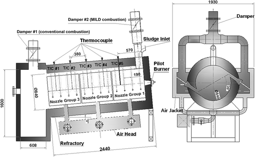
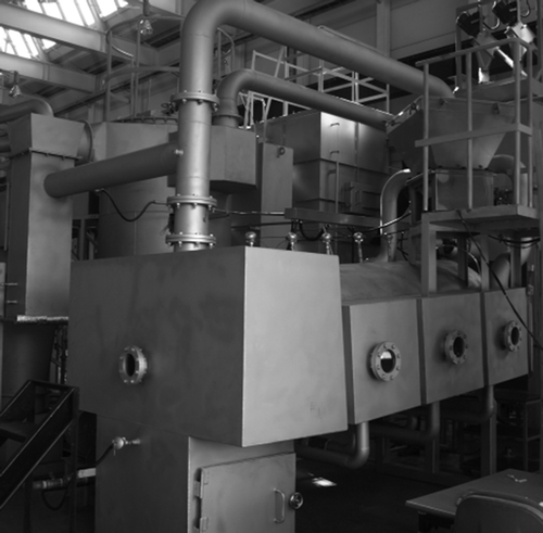
A laboratory-scale horizontal cyclone combustor with a 300 mm diameter and 830 mm length was tested in our previous study for the MILD combustion of dried sludge (Shim et al., Citation2014). The cyclone type of combustor was designed to provide a thorough mixing of sludge particles and air with sufficient turbulence and to reduce NOx emissions by MILD combustion. A pilot-scale cyclone combustor with recirculation was therefore constructed and tested in this study. The pilot-scale combustor was designed to treat up to 2 metric tons of dried sludge per day. The combustor had a dual-cylindrical shape 2440 mm in length, and the main combustion chamber had a diameter of 840 mm. A diagram with detailed dimension and a picture of the pilot-scale combustor are shown in and , respectively. As shown in , one window was located at the front side of the combustor for observing the combustion flame inside the combustion chamber. Six windows were located at the sides of the combustor for checking the flow patterns inside the combustor. There were 24 nozzles at the sides for reinjection of the combustion flue gas into the combustion chamber. The nozzles were divided into three groups, with the same dimensions within the same group.
Air nozzles and venturi tubes with sizes A and B were used, as shown in and . The nozzles with size A had different diameters among the three groups, whereas the nozzles with size B had the same diameter among the three groups. The nozzles and venturi tubes with size B had smaller diameters than those with size A.
Table 1. Dimensions of the air nozzles and venturi tubes (in mm)
Figure 3. Configuration of the air nozzles and venturi tubes (d: diameter of the air nozzle; Di: inlet diameter of the venturi tube; Dt: body diameter of the venturi tube; Do: outlet diameter of the venturi tube; g: gap between the venturi tube and the air nozzle).
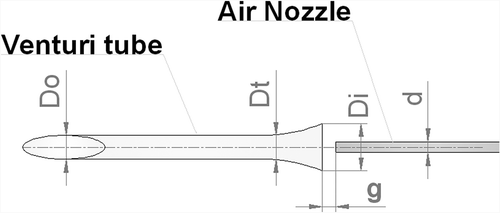
Two different configurations of venturi tubes were used: (1) straight-tip venturi tube and (2) round-tip venturi tube. As shown in , the straight-tip tube was designed to inject air along the wall of the combustion chamber, whereas the round-tip tube was designed to inject air into the middle of the cross-section perpendicular to the radius of the combustion chamber.
Figure 4. Two different configurations of the venturi tubes (left: straight-tip venturi tube; right: round-tip venturi tube).
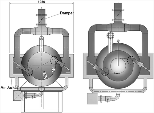
The temperatures inside the combustor were measured by five thermocouples (R type) placed along the length of the combustor and were recorded using the temperature logging system (GL450 midi logger; Graphtec Corp., Yokohama, Japan). Two dampers were installed to simulate the conventional and MILD combustion, respectively. When damper 1 was open and damper 2 was closed, the combustion flue gas was directly exhausted through damper 1, which simulated conventional air combustion. When damper 1 was closed and damper 2 was open, some of the combustion flue gas was entrained into the combustion chamber by air injected through the nozzles, and the rest of the combustion flue gas was exhausted through damper 2, which simulated MILD combustion.
Experimental procedure
The combustor was first preheated to a temperature higher than the autoignition temperature of the fuel using a premixed natural gas flame through the pilot burner. The pilot burner was switched off once the combustor temperature exceeded 850 °C. Dried sludge was then injected into the combustor at a constant rate. The size of the sludge particles ranged from 400 to 650 μm. The elemental contents of the dried sludge were 27.9% C, 4.2% H, 20.2% O, 3.6% N, and 0.01% S. The detailed description of the dried sludge sample can be found in our previous publication (Shim et al., Citation2014). Air was injected through the nozzles located at the sides of the combustor to entrain the combustion flue gas. To check the combustion stability, the temperatures inside the combustor were measured by five thermocouples and were monitored during the test. The combustion flame was monitored through the front and side windows. The concentrations of O2, CO, and NOx in the exhaust gas stream were measured with a gas analyzer (Vario Plus; MRU, Neckarsulm-Obereisesheim, Germany; accuracy is less than 5% reading).
Results and Discussion
Computational fluid dynamics analysis
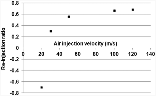
The pilot-scale horizontal cyclone combustor was designed to reinject high-temperature combustion flue gas into the combustion chamber for MILD combustion. Air was injected through the nozzles to entrain the combustion flue gas. Therefore, designing the air nozzles to sufficiently entrain the combustion flue gas is important for successful MILD combustion. A computational fluid dynamics (CFD) analysis was conducted to estimate the reinjection ratio of flue gas with an increase in the air injection velocity. The reinjection ratio is short for the ratio of the flue gas entrained into the combustor to the air injected through the nozzle in volumetric flow rates. The SIMPLE algorithm provided by a commercial program (Fluent 6.3; ANSYS Inc., Canonsburg, PA, USA) was used for the CFD analysis. shows the boundary conditions considered for the CFD analysis. These conditions are the same as the operating conditions of the pilot-scale combustor.
Table 2. Boundary conditions considered for the CFD analysis
shows the velocity vectors obtained from the CFD analysis when air was injected through the nozzle at 20, 50, and 100 m/sec, respectively. As shown in the figure, the injected air flowed backward at an air injection velocity of 20 m/sec, whereas it properly entrained the combustion flue gas into the combustor above the air injection velocity of 50 m/sec.
Figure 5. Velocity vectors obtained from the CFD analysis at air injection velocities of 20 (top), 50 (middle), and 100 (bottom) m/sec, respectively.
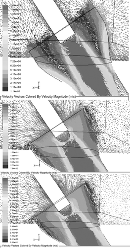
presents the reinjection ratios of the flue gas with the air injection velocities obtained from the CFD analysis. The reinjection ratio rapidly increased with an increase in the air injection velocity from 20 to 50 m/sec but increased logarithmically after 50 m/sec. The CFD analysis results suggest that the air injection velocity should be more than 50 m/sec to properly reinject the combustion flue gas into the combustor.
Effect of the configuration of the venturi tube
Several preliminary tests were conducted to determine the optimized design and operating conditions of the pilot-scale combustor for stable MILD combustion of dried sludge. As presented in , two different configurations of venturi tubes were tested: (1) straight-tip venturi tubes and (2) round-tip venturi tubes. The first combustion test was conducted with the round-tip tube. This venturi tube was designed to inject air into the middle of the cross-section perpendicular to the radius of the combustion chamber. Using the round-tip tube, very unstable combustion was found, although several tests were conducted with varying operating conditions, such as the sludge feed rate, air injection velocity, and excess air ratio. Our previous laboratory-scale test results suggested that a thorough mixing of the sludge particles with air is important for MILD combustion in the horizontal cyclone-type combustor. Hence, the unstable combustion with the round-tip tube may be ascribed to the poor mixing when air is injected into the middle of the combustion chamber. In addition, the round-tip tube may not allow the entrainment of the particles by recirculated gas. Some of the dried sludge particles may then be precipitated on the wall of the combustion chamber when the round-tip tube is used. After the round-tip tube was replaced with the straight-tip tube, more stable combustion was found. These results indicate that air injection along the wall of the combustion chamber leads to better recirculation inside the furnace. The following combustion tests were therefore conducted with the straight-tip venturi tube.
Effect of the air injection location
The air nozzles were located with the same interval along the length of the pilot-scale combustor. The nozzles were divided to three groups. Each group consisted of eight nozzles, as shown in . To examine the combustion stability with the combination of groups, combustion tests were conducted using the nozzles in (1) groups 1 and 2, (2) groups 1 and 3, (3) groups 2 and 3, and (4) group 1. Using the air nozzles close to the sludge inlet was beneficial for stable combustion. The tests using the nozzles in group 3 showed very unstable combustion. This may be ascribed to the lower residence time of air injected through the nozzles in group 3 inside the furnace. In addition, the fed sludge particles may settle under the fuel feed point when air is not injected through the nozzles in group 1. This result is consistent with the findings of our previous laboratory-scale tests (Shim et al., Citation2014).
Effect of the air injection velocity
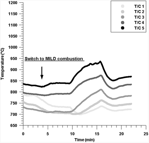
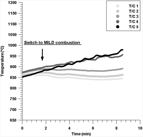
Further tests were conducted by varying the nozzle size to investigate the effect of the air injection velocity on MILD combustion in the pilot-scale combustor. Because the nozzles with size A have larger diameters than those with size B, a lower reinjection ratio is expected with size A due to a lower air velocity. The first combustion test was conducted with the size A nozzle. Dried sludge was fed into the combustor at a rate of 80 kg/hr and combusted at an excess air ratio of 1.05. Due to the low air injection velocity at those conditions, only the nozzles in group 1 were used. The air injection velocity through the nozzle was 26.5 m/sec, at which little reinjection of flue gas was expected based on the CFD analysis results. shows the NOx and CO concentrations normalized to 12% O2 in the exhaust gas stream during the test. Although the NO concentration slightly decreased after the switch to MILD combustion, very high CO emissions were found in both the conventional and MILD combustion modes. The reduction in NOx emission may indicate that some high-temperature flue gas was entrained into the combustor at the air injection velocity of 26.5 m/sec. The slight increase in the temperature at thermocouple 5 in may also be attributed to the entrainment of high-temperature flue gas. However, the high CO concentrations ranging approximately from 500 to 1500 ppm indicate unstable combustion during the MILD mode. The difference in temperatures measured by the five thermocouples did not decrease after the switch to MILD combustion, although the MILD combustion by flue gas recirculation was designed to smooth the temperature field within the combustor and to decrease the adiabatic flame temperature.
Figure 7. NOx and CO concentrations normalized to 12% O2 in the exhaust gas from the combustion of dried sludge at 80 kg/hr with an air injection velocity of 26.5 m/sec through nozzle A.
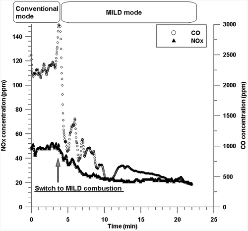
Figure 8. Temperature variation inside the combustor during the combustion at 80 kg/hr with an air injection velocity of 26.5 m/sec through nozzle A.
The next combustion test was conducted with an increased air injection velocity of 40 m/sec through the size A nozzle by increasing the excess air ratio to 1.45. Compared with the test at 26.5 m/sec, the CO emissions significantly decreased for both combustion modes, as shown in . The NOx concentration did not change before the switch to MILD combustion and then began to decrease at approximately 2.5 min after the switch. The NOx concentration was not consistent during the MILD combustion. The CO concentration was as high as more than 100 ppm. Similar to the test at 26.5 m/sec, the temperatures at thermocouples 4 and 5 increased slightly, and the difference in temperature did not decrease after the switch to MILD combustion, as shown in . This indicates that the combustion at 40 m/sec was still unstable even though the CO emission decreased. For both tests at 26.5 and 40 m/sec, very high levels of CO emissions were found from the conventional combustion mode. This shows that internal circulation is also important in the conventional combustion mode.
Figure 9. NOx and CO concentrations normalized to 12% O2 in the exhaust gas from the combustion of dried sludge at 85 kg/hr with an air injection velocity of 40 m/sec through nozzle A.
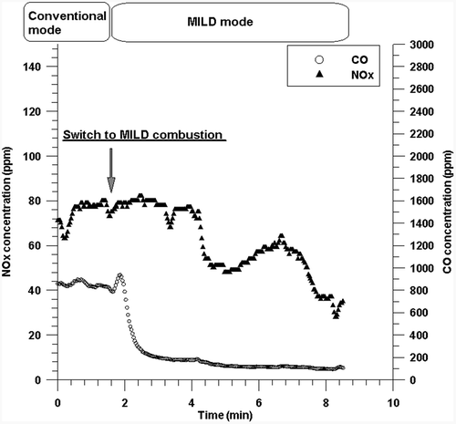
Figure 10. Temperature variation inside the combustor during the combustion at 85 kg/hr with an air injection velocity of 40 m/sec through nozzle A.
The air nozzles with size A were therefore replaced by the nozzles with size B. The diameter of the size B nozzle is half the diameter of the size A nozzle in group 1. Whereas only nozzles in group 1 were used in the tests with nozzle size A to inject air at 26.5 and 40 m/sec, eight nozzles in group 1 and six nozzles in group 2 were used in this test to increase the air injection velocity to 68 m/sec. With the increased air injection velocity, dried sludge was fed into the combustor at a rate of 85 kg/hr and combusted at an excess air ratio of 1.08. In this test, dried sludge was first combusted in a MILD combustion mode and then switched to a conventional combustion mode. As shown in , the CO concentration significantly decreased, whereas the NOx concentration was similar to the results from the tests at 26.5 and 40 m/sec. After switching to the conventional mode, the NOx concentration significantly increased and became approximately 3 times higher than that in the MILD combustion mode. shows the temperature variation inside the combustor during the MILD and conventional combustion. After switching to conventional combustion, the temperatures in thermocouples 1 and 2 increased, whereas the temperatures in thermocouples 3, 4, and 5 decreased, which showed that the difference in the temperature inside the combustor increased.
Figure 11. NOx and CO concentrations normalized to 12% O2 in the exhaust gas from the combustion of dried sludge at 85 kg/hr with an air injection velocity of 68 m/sec through nozzle B.
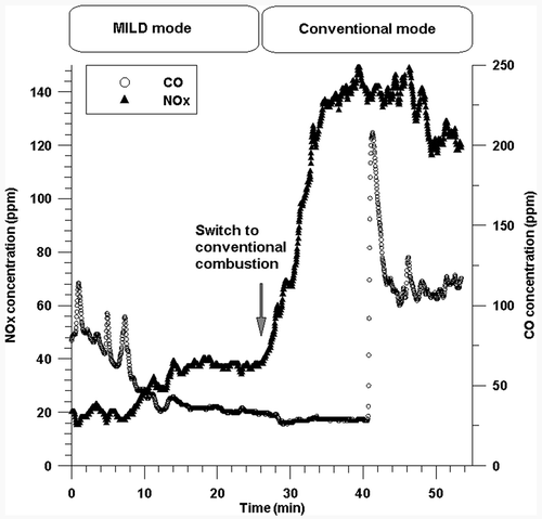
Figure 12. Temperature variation inside the combustor during the combustion at 85 kg/hr with an air injection velocity of 68 m/sec through nozzle B.
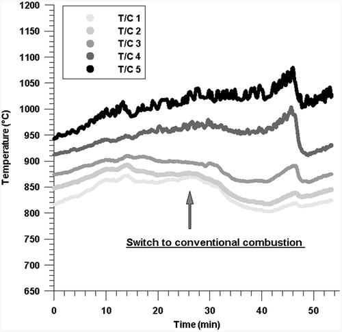
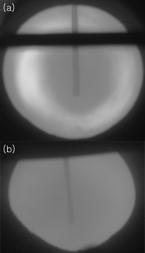
This shows that the combustion flame is formed where the dried sludge is injected during the conventional combustion mode, as shown in the picture in . In contrast, the combustion flame was not observed during MILD combustion due to even distribution of the temperature inside the combustor, as shown in . The NOx emission from the MILD combustion was one-third of that from the conventional combustion, whereas the CO emission was maintained below 100 ppm. This shows that the air injection velocity is an important parameter to achieve MILD combustion of dried sludge using the cyclone-type combustor.
Results from stable MILD combustion
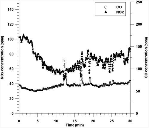
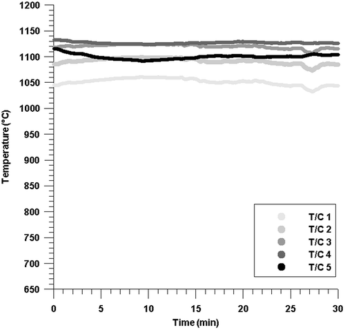
Despite of the reduction in NOx emission, the results from the test at 68 m/sec showed relatively high variation in the concentrations of NOx and CO of 15~40 and 40~100 ppm, respectively. Further combustion tests were conducted with an air injection velocity of 68 m/sec in a MILD combustion mode to obtain more consistently stable combustion. This test was conducted with a decreased feed rate of dried sludge of 75 kg/hr. The excess air ratio of 1.05 was similar to the previous test. The preheating temperature was increased from 850 to 1000 °C. As shown in the results in , the NOx and CO concentrations varied in the ranges of 50~85 and 55~75 ppm, which are below the Korean emission standards for NOx and CO, 90 and 200 ppm, respectively. The CO concentration was also consistently maintained, which indicated stable MILD combustion. This suggests that the standards for the NOx and CO emissions from the sewage sludge incinerator can be met by MILD combustion without applying flue gas treatment techniques. The temperatures at each thermocouple were constant with time. The difference in the temperature inside the combustor was less than 100 °C, and the temperature at each thermocouple barely changed with time, as shown in . The slightly higher NOx concentration may be attributed to the improved mixing inside the combustor caused by decreasing the sludge feed rate and to the increased temperature inside the combustor. However, the NOx concentration in the increased temperature was lower than the Korean emission standard. These results show successful MILD combustion of the dried sludge with the increased air injection velocity in the pilot-scale horizontal cyclone combustor.
Conclusion
A pilot-scale horizontal cyclone combustor was designed and operated to achieve the MILD combustion of dried sewage sludge. The combustor was designed to be capable of injecting high-velocity air into the combustion chamber and preheating and diluting the air with flue gas. Through CFD analysis, the reinjection ratio of flue gas into the combustion chamber was first estimated. An air injection velocity of more than 50 m/sec was required to reinject the flue gas properly into the combustion chamber. The experimental results demonstrated that the injection of air using a straight-tip venturi tube created better recirculation inside the furnace, and the use of nozzles close to the fuel inlet was beneficial for stable combustion due to the longer residence time of air inside the furnace. High-velocity air was critical to obtain stable MILD combustion. Significant reduction in NOx emission was found in the MILD combustion mode at an air injection velocity of 68 m/sec, whereas high levels of CO and NOx emissions were found from the MILD combustion at 26.5 and 40 m/sec, respectively. Consistent with the findings in the literature, high-momentum air was a key parameter of the MILD combustion of dried sludge in the pilot-scale cyclone combustor. With optimized conditions, the pilot-scale combustor demonstrated the MILD combustion of dried sludge at a rate of 75 kg/hr with an excess air ratio of 1.05. Low levels of CO and NOx emissions of 50~85 and 55~75 ppm, respectively, were found. These results suggest that MILD combustion technology with the cyclone-type furnace is a suitable option for reducing NOx emissions from the combustion of dried sewage sludge.
Acknowledgment
The authors thank Dr. Ji Soo Ha at Keimyung University for his help with CFD analysis.
Funding
This research was supported by a research project from Korea Institute of Machinery and Materials (KIMM).
Additional information
Funding
Notes on contributors
Sung Hoon Shim
Sung Hoon Shim and Sang Hyun Jeong are principal researchers in the Division of Environmental and Energy Research at Korea Institute of Machinery & Materials (KIMM), Daejeon, Korea.
Sang Hyun Jeong
Sung Hoon Shim and Sang Hyun Jeong are principal researchers in the Division of Environmental and Energy Research at Korea Institute of Machinery & Materials (KIMM), Daejeon, Korea.
Sang-Sup Lee
Sang-Sup Lee is an associate professor in the Department of Environmental Engineering at Chungbuk National University, Cheongju, Korea.
References
- Champion, W.M., C.D. Cooper, K.R. Mackie, and P. Cairney. 2014. Development of a chemical kinetic model for a biosolids fluidized-bed gasifier and the effects of operating parameters on syngas quality. J. Air Waste Manage. Assoc. 64:160–174. doi:10.1080/10962247.2013.845619
- Cichanowicz, J.E. 2010. Current capital cost and cost-effectiveness of power plant emissions control technologies. http://www.publicpower.org/files/PDFs/UARGSCR_FGDFinal.pdf (accessed December 3, 2014).
- Cooper, C.D., and F.C. Alley. 2011. Air Pollution Control: A Design Approach, 4th ed. Long Grove, IL: Waveland Press.
- Dally, B.B., S.H. Shim, R.A. Craig, P.J. Ashman, and G.G. Szegö. 2010. On the burning of sawdust in a MILD combustion furnace. Energy Fuels 24:3462–3470. doi:10.1021/ef901583k
- Houshfar, E., T. Løvås, and Ø. Skreiberg. 2012. Experimental Investigation on NOx reduction by primary measures in biomass combustion: Straw, peat, sewage sludge, forest residues and wood pellets. Energies 5:270–290. doi:10.3390/en5020270
- Khoshhal, A., M. Rahimi, and A.A. Alsairafi. 2011. CFD study on influence of fuel temperature on NOx emission in a HiTAC furnace. Int. Commun. Heat Mass 38:1421–1427. doi:10.1016/j.icheatmasstransfer.2011.08.008
- Mei, Z., P. Li, F. Wang, J. Zhang, and J. Mi. 2014. Influences of reactant injection velocities on moderate or intense low-oxygen dilution coal combustion. Energy Fuels 28:369–384. doi:10.1021/ef401509e
- Mi, J., F. Wang, P. Li, and B.B. Dally. 2012. Modified vitiation in a moderate or intense low-oxygen dilution (MILD) combustion furnace. Energy Fuels 26:265–277. doi:10.1021/ef201161x
- Mosca, S., P. Benedetti, E. Guerriero, and M. Rotatori. 2014. Assessment of N2O emission from cement plants: Real data measured with both FTIR and NDIR. J. Air Waste Manage. Assoc. 64:1270–1278. doi:10.1080/10962247.2014.936986
- Schaffel-Mancini, N., M. Mancini, A. Szlek, and R. Weber. 2010. Novel conceptual design of a supercritical pulverized coal boiler utilizing high temperature air combustion (HTAC) technology. Energy 35:2752–2760. doi:10.1016/j.energy.2010.02.014
- Shim, S.H., S.H. Jeong, and S.-S. Lee. 2014. Reduction in nitrogen oxides emissions by MILD combustion of dried sludge. Renew. Energ. 65:29–35. doi:10.1016/j.renene.2013.07.005
- Shimizu, T., and M. Toyono. 2007. Emissions of NOx and N2O during co-combustion of dried sewage sludge with coal in a circulating fluidized bed combustor. Fuel 86:2308–2315. doi:10.1016/j.fuel.2007.01.033
- Stadler, H., D. Ristic, M. Förster, A. Schuster, R. Kneer, and G. Scheffknecht. 2009. NOx-emissions from flameless coal combustion in air, Ar/O2 and CO2/O2. Proc. Combust. Inst. 32:3131–3138. doi:10.1016/j.proci.2008.06.025
- Suda, T., M. Takafuji, T. Hirata, M. Yoshino, and J. Sato. 2002. A study of combustion behavior of pulverized coal in high-temperature air. Proc. Combust. Inst. 29:503–509. doi:10.1016/S1540-7489(02)80065-7
- Vascellari, M., and G. Cau. 2012. Influence of turbulence-chemical interaction on CFD pulverized coal MILD combustion modeling. Fuel 101:90–101. doi:10.1016/j.fuel.2011.07.042
- Wünning, J.A., and J.G. Wünning. 1997. Flameless oxidation to reduce thermal no-formation. Progr. Energy Combust. Sci. 23:81–94. doi:10.1016/s0360-1285(97)00006-3
- Wang, Y.D., Y. Huang, D. McIlveen-Wright, J. McMullan, N. Hewitt, P. Eames, and S. Rezvani. 2006. A techno-economic analysis of the application of continuous staged-combustion and flameless oxidation to the combustor design in gas turbines. Fuel Process. Technol. 87:727–736. doi:10.1016/j.fuproc.2006.02.003

