
Abstract
Methane (CH4) is the dominant greenhouse gas emitted by animal agriculture manure. Since the gas is relatively insoluble in water, it is concentrated in discrete bubbles that rise through waste lagoons and burst at the surface. This results in lagoon emissions that are inhomogeneous in both space and time. Emissions from a midwestern dairy waste lagoon were measured over 2 weeks to evaluate the spatial homogeneity of the source emissions and to compare two methods for measuring this inhomogeneous emission. Emissions were determined using an inverse dispersion model based on CH4 concentrations measured both by a single scanning tunable diode laser (TDL) aimed at a series of reflectors and by flame ionization detection (FID) gas chromatography on line-sampled air. Emissions were best estimated using scanned TDL concentrations over relatively short optical paths that collectively span the entire cross-wind width of the source, so as to provide both the best capture of discrete plumes from the bursting bubbles on the lagoon surface and the best detection of CH4 background concentrations. The lagoon emissions during the study were spatially inhomogeneous at hourly time scales. Partitioning the inhomogeneous source into two source regions reduced the estimated emissions of the overall lagoon by 57% but increased the variability. Consequently, it is important to assess the homogeneity of a source prior to measurements and final emissions calculation.
Implications: Plans for measuring methane emissions from waste lagoons must take into account the spatial inhomogeneity of the source strength. The assumption of emission source homogeneity for a low-solubility gas such as CH4 emitted from an animal waste lagoon can result in significant emission overestimates. The entire breadth and length of the area source must be measured, preferably with multiple optical paths, for the detection of discrete plumes from the different emitting regions and for determining the background concentration. Other gases with similarly poor solubility in water may also require partitioning of the lagoon source area.
Introduction
Methane (CH4) is a major contributor to the agricultural sector greenhouse gas emissions. As of 2012, manure management contributed approximately 26% of the CH4 produced by agriculture (U.S. Environmental Protection Agency [EPA], Citation2014). It is estimated that CH4 emissions from manure management on dairy operations have increased 53% between 2000 and 2012 (EPA, Citation2014). However, the reported CH4 emissions are based on emission factors developed from a very limited number of actual in situ emission measurements.
Reported CH4 emissions from waste storage facilities vary widely. Emissions from the wastewater pond of one Idaho open-lot dairy during 13 days of measurements across 6 months ranged from 0.18 to 2.13 kg day−1 hd−1 (hd = animal) (Leytem et al., Citation2010). In a second study, wastewater pond CH4 emissions from another Idaho open-lot dairy over 5 days across 4 months ranged from 0.21 to 0.55 kg day−1 hd−1 (Bjorneberg et al., Citation2009). In both studies, the emissions were determined using inverse dispersion modeling on line-integrated concentration measurements across the entire downwind side of the lagoon and it was assumed that the lagoons were homogeneous CH4 emission sources.
Methane is biologically produced from methanogenesis of various volatile organic components in solid dairy waste (Casey et al., Citation2006). Since these solids are primarily found in the sludge, most CH4 is produced at the bottom of the lagoon or basin. Since methane has a low solubility in water, the CH4 produced forms bubbles attached to the solid surfaces where the bacteria exist. In freshwater lakes, such ebullition results in distinctly spatially and temporally heterogeneous distributions of CH4 emission events (Varadharjan and Hemond, Citation2012). The low solubility also leads to much higher CH4 concentrations in the bubbles than in the liquid, causing heterogeneity in space and time of CH4 emissions. In contrast, ammonia (NH3) has a high water solubility and consequently diffuses into the air over the entire lagoon surface as a function of the concentration gradient between the liquid and gaseous phases (Ni et al., Citation2009).
Little is known about the homogeneity of the emissions from a waste lagoon. A tomography study of the NH3 concentration across a hog lagoon showed distinct “hot spots,” suggesting underlying variability in lagoon emissions (Todd et al., Citation2001). Given that the processes controlling CH4 emissions are more discrete than NH3, we would expect inhomogeneous CH4 emissions across the lagoon. Therefore, the assumption of homogenous CH4 emissions across a lagoon needs to be tested.
In this study, the CH4 emissions from an anaerobic dairy waste lagoon were measured with the objectives of determining if the emissions were inhomogeneous in space at hourly time scales and evaluating the impact of inhomogeneities in lagoon emissions on the emission measurement results obtained using scanning tunable diode lasers (TDLs) with an inverse dispersion model.
Methods
Methane emission were measured at a midwestern dairy using an inverse dispersion model based on CH4 concentrations measured by both TDL absorption spectroscopy and flame ionization (FID) gas chromatography and turbulence statistics based on measurements made on-site.
Farm description
The study farm was a free stall dairy consisting of three barns, a feed storage area, a special needs barn, a milking parlor, an office, and tool and repair shops (Grant and Boehm, Citation2010). The facility had a capacity of 2600 cows, with a population during the study of 2580. The dairy was completed in 2002, and sludge had yet to be removed from the lagoon. The measured lagoon received wastewater (flush) from the holding area and milking parlor. Milking occurred twice daily, with flush occurring periodically during and immediately after each milking. The waste was first transferred into a rectangular settling basin north of the lagoon with a weir limiting the solids held in the lagoon. The inlet to the lagoon was located at its north end. The clay-lined waste lagoon was oriented north-south, had dimensions of 85 m by 116 m, a surface area of 9884 m2, a maximum liquid depth of 5 m, and volume of 48,212 m3 at maximum capacity. Since the lagoon was inherently a source of gases emanating from manure and effluent residing in the lagoon for multiple months, and the lagoon being monitored received effluent from the parlor and holding area, it was assumed that the number of animals contributing to the lagoon was the maximum capacity of the farm.
Measurements
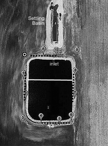
Path-integrated methane gas concentrations (PICs) were measured using a scanning TDL system (Boreal Laser, Ltd., Edmonton, Alberta, Canada) along optical paths defined by the TDL and retroreflectors. The retroreflectors were distributed around the lagoon to optimize the occurrence of downwind measurements during the measurement period (). The optical paths (OPs) were 33, 59, and 98 m long along the north side of the lagoon; 47, 88, and 136 m long along the west side of the lagoon; and 133, 150, 153, 120, and 94 m long across the lagoon. A scanner attached to the TDL sequentially aimed the TDL at the 11 retroreflector arrays, with a dwell of 10 sec on each array (termed “TDL/OP”). Typically there were 7–11 1.2-sec measurements made within the dwell time on each retroreflector. No on-site calibration tests were made to check the TDL performance.
Figure 1. Experimental layout. The TDL scanner system (circle with dot) was located at the northwest corner of the lagoon. Locations of retroreflectors, demarcating the termination of the OP in the TDL/OP measurement system, are indicated by the labeled locations. The locations of the four SOPS of the FID/SOPS measurement system are indicated by the dashed lines. The source was modeled both as a whole and in two distinct source regions separated by the white line.
The control of and data collection from the TDL system were accomplished by asynchronous RS232 serial communications through radio frequency (RF) modems with a laptop computer running the Boreal Laser Inc. GasViewMP software program (Boreal Laser, Ltd, Edmonton, Alberta, Canada). The software used an optimization scheme to keep the TDL aligned with each retroreflector. However, some individual paths were lost at various times during the study period due to condensation. Most of the retroreflector arrays were mounted on a heated back plate within National Electrical Manufacturers Association (NEMA) boxes that minimized the impact of dew on the NEMA box optical windows.
To ensure that the absorption detected by the TDL is in fact due to CH4, the sample waveform was compared with the waveform of an internal gas calibration cell at the time of each measurement record. The correlation between the two waveforms is described as a linear correlation coefficient (R2) value. The waveform of the internal cell was also compared at regular intervals with that made during the factory multipoint calibration at a set interval. High correlation between the internal and sample waveforms and between the internal and reference calibration waveforms is necessary for a valid measurement. The mean path-integrated concentration (PIC) over a 60-min period was determined from the averaged PIC values for each 10-sec dwell period.
To help achieve the objectives of this study, emissions were calculated based on 15 subsets (termed “schemes”) of between 2 and 11 optical paths. These subsets can be broken into the following three broad categories: (1) only paths along the edge of the source area, (2) only paths over the source area, and (3) paths over and along the edge of the source area.
Methane concentrations were also measured using FID (model TEC 55C; Thermo Fisher Scientific, Franklin, MA, USA) on air collected along 50-m synthetic open path systems (SOPS) located at 1 m above berm level (abl) on the north, south, east, and west berms of the lagoon () and sampled through a gas sampling system (GSS) that drew the air through the SOPS (termed “FID/SOPS”; 5). The FID performed an automated span check each evening that the instrument was functioning. During this check, the instrument drew air from a calibration cylinder with a concentration of about 10 μL L−1. Multipoint calibrations conducted at the beginning and end of the experiment showed an offset of 0 and a linear relationship between the instrument reading and introduced concentration. The mean value of this calibration coefficient was used to correct the measurements. After the correction was applied, the error in the automated daily span check ranged from −3.7% to 4.3%, with a standard deviation of 1.4%. All CH4 concentration measurements were normalized to 101.325 kPa and 20 °C (standard temperature and pressure [STP]) within the instruments.
Each SOPS consisted of 10 inlets fitted with 1 mm Teflon filters to limit particulate contamination of the FID. Critical orifices in the inlets were adjusted so that each inlet had the same flow rate (±10%). Inlets were spaced 5 m apart. The flow through the SOPS was maintained at least 7 L min−1 and sampled by the GSS, which sequentially drew from each of the SOPS every 15 min. The lag time for propane transit between starting the draw of air through a given SOPS and its receipt at the analyzer was measured to be less than 1 min per 235 m tube length. All tubing was 3/8 in. diameter Teflon tube. Only the last 2 min of the 15-min sampling interval were used for emission determination. One complete cycle of the SOPS required 1 hr. The upwind concentration was assumed to be the best estimate of the measured background concentration (Cbg) for the emission estimate.
Meteorological measurements of barometric pressure (278; Setra, Inc., Boxborough, MA, USA), air temperature and relative humidity (HMP45C; Vaisala, Inc., Helsinki, Finland), and solar radiation (210; LiCOR, Inc., Lincoln, NE, USA) were located on a mast located on the berm 5 m west and 30 m north from the southwest berm corner. All measurements were averaged to ½-hr intervals to match a half-cycle of SOPS measurements. A three-dimensional (3D) sonic anemometer (model 81000; RM Young Inc., Traverse City, MI, USA) was located on the meteorological tower at a height of 2.5 m. The 300-sec sonic data files were averaged to ½-hr or 1-hr intervals. To be considered a valid 300-sec period, at least 90% (4320) of the possible 4800 16-Hz values had to be present and the sonic temperature variance had to be less than 2.5 K2.
A backward Lagrangian stochastic (bLS) model (WindTrax; Thunder Beach Scientific, Nanaimo, BC, Canada; http://www.thunderbeachscientific.com) was used to determine the emission rates based on measured gas concentrations and wind statistics. The bLS model (Flesch et al., Citation2004) quantifies the ratio between the difference between the downwind and upwind (background) concentrations (Ci − Cbg) and the average surface flux density across the source area (Fc,0) with the assumption that the ratio, ai = (Ci − Cbg)/Fc,0, is only a function of flow characteristics. To determine this ratio, the model simulates the flight path of air parcels backwards from the optical path until each parcel intersects the ground (a “touchdown”). The number of impacts within the lagoon, weighted by the velocity at touchdown (w0), divided by the number of parcels (n) released from 10 equidistant points along each OP or SOPS provided the ratio ai:
The model then calculated the emission rate (Q) for each set of concentration measurements by simultaneous solution of multiple equations (one for each SOPS or OP) using the standard singular value decomposition algorithm. Since the solution is overdetermined, Cbg is also determined by the model algorithm. Emissions were excluded from analysis if (1) the friction velocity (u*) was less than 0.15 m sec−1, (2) the Obukov length |L| was less than 2 m, or (3) the fraction of backward trajectory parcel impacts in the lagoon (touchdown fraction) was less than 0.1 (Flesch et al., Citation2004).
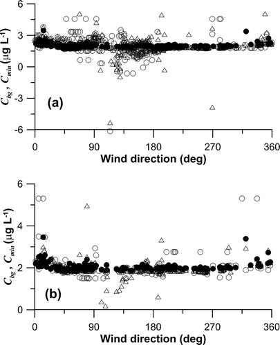
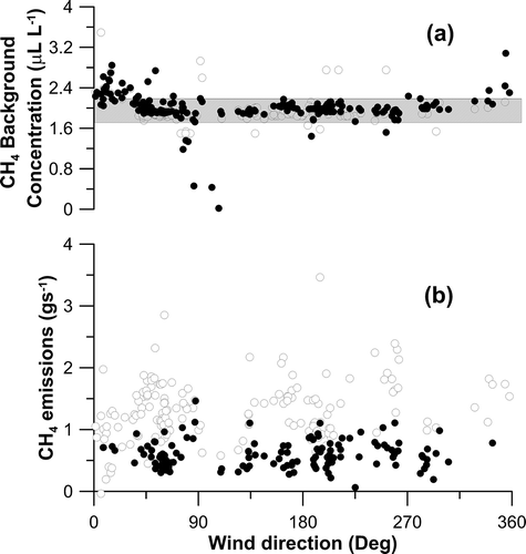
Nonconformity of the TDL PICs for the assumed uniform source area(s) (discussed below) used in the bLS emission estimate increases the confidence interval of the estimate. One measure of the nonconformity of the measurements to the source scenario is the model-derived Cbg. If the Cbg is underestimated by the bLS model, there is the potential for overestimating the emissions. If the Cbg is overestimated by the bLS model, there is the potential for underestimating the emissions. The minimum FID/SOPS concentrations over the study period averaged 2.03 μL L−1 (SD = 0.19 μL L−1), while the corresponding bLS-derived Cbg was 1.98 μL L−1 (). Emissions based on the TDL measurements were further constrained by a requirement that the model-derived Cbg must be between 1.7 and 2.2 μL L−1.
A comparison between the minimum FID-measured C and TDL/OP model-estimated Cbg for similar paths over a given hour was used to evaluate the ability of the bLS-modeled emissions based on the TDL/OP configuration to give a comparability of emission estimate validation. The difference between the minimum FID/SOPS-measured concentration and the model-estimated Cbg from TDL/OP measurements, based on all paired measurements (n = 285), was 0.016 μL L−1 (SD = 0.325 μL L−1). Since a true Cbg could be measured only when at least one TDL path was upwind of the source, whether or not the lowest concentration paths were truly upwind of the source in part defines the quality of the source emission estimate. The quality of the Cbg determined by bLS was related to the wind direction. Wind directions from the southeast to south (100° through 225°) had relatively large differences between the bLS-determined Cbg based on the TDL/OP- and FID/SOPS-measured minimum concentrations (). For these wind directions, no upwind TDL/OP is possible given the configuration of the TDL scanning system (). Excluding measurements within this wind direction range resulted in a mean difference of 0.006 μL L−1 (SD = 0.209 μL L−1) (n = 174). This mean difference was also not significant at the 95th percentile. The lack of significant difference indicates that the sequentially measured concentrations from the TDL/OP and the FID/SOPS are representative of the entire hour.
Figure 2. Comparison of background CH4 concentrations and minimum FID/SOPS concentration measurements. The variations in minimum measured FID/SOPS CH4 concentration and the bLS-derived background concentration (Cbg) for the TDL/OP scheme 2 for the one source (open circles) and two sources (open triangles) with wind direction are indicated in panel (a). The variations in minimum measured FID/SOPS CH4 concentration and the bLS-derived background concentration (Cbg) for the one source (open circles) and two sources (open triangles) with wind direction are indicated in panel (b).
Emission detection limits
The instrument minimum detection limit (MDL) was defined as 3 times the standard deviation (σ) of the instrument reading while sampling a steady known concentration. The MDL for the FID analyzer was 0.098 mL L−1 based on measurements during zero calibration checks. The least significant difference (LSD) in FID concentrations across the lagoon at the 95% significance level was determined as LSD = 1.96(2 σ2)1/2. The LSD for the FID analyzer was 0.091 mL L−1. Methane emissions determined using the FID were qualified by assuring that the difference in concentration across the lagoon (ΔC), obtained by exceeded the LSD. Approximately 99% of the CH4 measurements across the lagoon had ΔC >LSD.
Results
Measurements were made between 5 and 17 November 2009. Over that period, air temperatures ranged from 0 to 20 °C and the maximum wind speed was 7 m sec−1. The barometric pressure varied from 95.6 to 100.3 kPa. The lagoon appeared brown and had less than 10% crusting on the surface during the measurement period. Comparisons of the TDL/OP and FID/SOPS measurement systems and the emission results obtained from these measurements were conducted using 187 hr of valid measurements within the measurement period.
Line-averaged concentrations
Methane concentrations along the berm were measured by FID of air sampled by the SOPS around the four sides of the lagoon and by open-path TDL along the west and north sides of the lagoon. The mean FID/SOPS concentration along the north side of the lagoon was greatest under southerly winds, as was the west side under easterly winds (). The west SOPS was approximately in the line between retroreflectors 1 and 2 (). The mean difference (TDL/OP − FID/SOPS) between the two measurements was 1.45 ± 4.77 μL L−1 along the west side, where two TDL paths were subtracted from one another to approximate the SOPS path. The north SOPS was approximately along the OP for retroreflector 10 (). The mean difference between the two measurements was 0.56 ± 2.71 μL L−1. Mixing of the air from the lagoon influenced the differences between the TDL/OP and FID/SOPS concentration measurements, with differences between the measurements relatively stable for u* above 0.15 m sec−1 (). Considering only unstable boundary layer conditions when the best mixing might be expected, the mean difference between the two paths on the west side was 1.80 ± 4.75 μL L−1, whereas that on the north side was 0.08 μL ± 2.05 μL L−1. The correlation between measured concentrations varied more on the north side than the west side (). The north side of the lagoon may be expected to have a distinctly inhomogeneous emission near the berm because the inlet was located there.
Figure 3. Comparison between CH4 concentration measurements made using the FID/SOPS and the TDL/OP measurement systems. The equivalent concentrations from the FID/SOPS and TDL/OP measurements along the corresponding path on the north (a) and west (b) sides of the lagoon are shown. The relationships during unstable (open circles) and stable (closed circles) surface boundary layers are indicated.
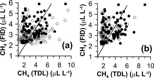
Figure 4. Influence of friction velocity on differences in CH4 concentration measurements made along the north and west sides of the lagoon. The differences in concentrations measured from the north and west components of the FID/SOPS measurement system and the corresponding TDL OP are indicated relative to friction velocity (a) and wind direction (b).
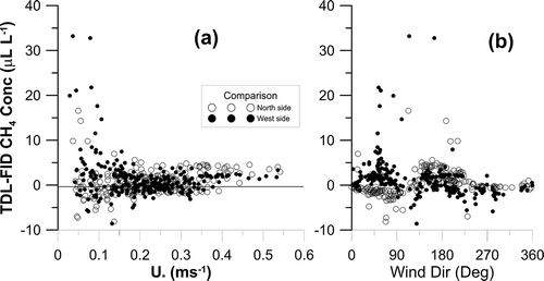
Several factors contribute to the differences in concentration measurements between the two methods. One is measurement of different portions of the emission plume because of differences in integration time of the measurements (FID/SOPS concentration measurements taken at 28–30 and 43–45 min after each hour, whereas TDL/OP concentration measurements taken for 10 sec each every approximately 5 min). Another factor is the slight differences in path length. Yet another factor is the slightly different distances of the measurement paths from the lagoon edge. There was a tendency for the TDL/OP to be less than the FID/SOPS concentration on the west side of the lagoon and more than the FID/SOPS concentration on the north side of the lagoon when winds were from the north to east. Differences between the west and north side FID/SOPS and TDL/OP concentration measurements were similar for all other wind directions (). On the north side, the path was nearly identical length, but the TDL/OP was slanted towards the lagoon looking east whereas the FID/SOPS was close to the lagoon throughout its integration path. Consequently, the higher concentrations from the TDL/OP over the FID/SOPS cannot be explained by proximity to the lagoon source. However, plumes of emissions from the settling basin on the north side of the lagoon would contribute more to the TDL/OP path than the FID/SOPS path and may explain the difference in concentration measurements (). On the west side, the OP and SOPS were similar, although the TDL/OP was slanted towards the lagoon looking south. The greater distance from the lagoon of the TDL/OP may explain the lower concentrations when winds are from the north.
PICs were measured along five OP across the lagoon (4, 5, 6, 7, 8; ), similar to the tomographic mapping of NH3 (7). As found for NH3 (7), there were large differences among the PICs along the various OP for a given time. Variability in concentration across the lagoon was greatest when there was little mixing (u* < 0.1 m sec−1), particularly with winds out of the north to east (). In general, the standard deviation in across-lagoon measurements was linearly related to the mean concentration. When u* was at least 0.1 m sec−1, the relationships among the optical path concentrations were reasonably steady for a given wind direction (). The air temperature was lower and wind speed higher with easterly winds than from all other directions (). The most common situation was southerly winds advecting warm air across the colder November ground resulting in a mean stable condition at the lagoon compared with winds from all other directions ().
Figure 5. Time history of TDL/OP CH4 concentrations across the lagoon during stable periods. Note the rapid increases evident when the boundary layer conditions become stable (hashed regions) and friction velocities are less than 0.15 m sec−1.
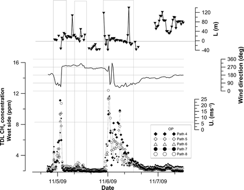
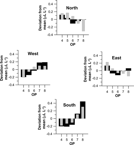
Figure 6. Across-lagoon variability in TDL/OP CH4 concentrations. The deviation from mean lagoon CH4 concentrations is indicated for the five OPs across the lagoon when the u* values were greater than 0.15 m sec−1.
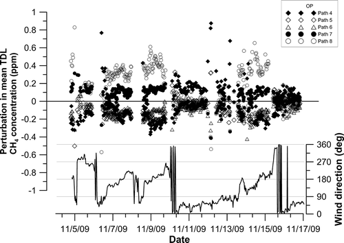
Table 1. Variation of conditions by wind direction*.
Table 2. Mean emission characteristics excluding wind directions resulting in poor background concentration determination.
The inverse dispersion model was used in “forward” mode to estimate the concentration at each OP across the lagoon, assuming atmospheric conditions similar to the mean conditions () with a homogeneous source of strength 150 μg m−2 sec−1 and a boundary layer with stability of z/L = −0.025 and u* = 0.22 m sec−1. Wind directions were set to each cardinal direction. The concentration variations along each OP across the lagoon from the grand mean of all across-lagoon OPs are illustrated in . Comparing the actual mean concentration in each cardinal direction with that predicted based on a homogeneous source showed large differences between the measured and observed concentrations for OP 8 under northerly and easterly winds (). This suggested that the lagoon surface was not a homogeneous emitting surface ().
Figure 7. Influence of wind conditions on TDL/OP-measured CH4 concentration variability across the lagoon. The association of wind direction with the measured variation in mean concentration along the OPs 4 through 8 that are over the lagoon (black bars), and the variation in concentration over the lagoon based on a modeled uniform source described in text.
Methane emissions
Methane emissions determined from the FID/ SOPS system were assumed to be the best estimate of the lagoon emissions, since CH4 concentrations were measured from line-sampled air along all sides of the lagoon. The mean emission during the study period was estimated to be 145 ± 45 μg m−2 sec−1 on an area basis or 0.049 ± 0.015 kg day−1 hd−1 on an animal basis. As expected, these emissions for stored manure derived from the milking parlor and holding area are lower than the reported CH4 emissions for lagoons under similar air temperature regimes at western open-lot dairies that receive manure from both the milking parlor and lot runoff (Bjorneberg et al., Citation2009; Leytem et al., Citation2010). Whereas CH4 concentrations were highest on the north side of the lagoon under southerly winds and on the east side under westerly winds (), the lowest fluxes and highest Cbg occurred under northerly winds (). Low emissions under northerly winds were probably an underestimate of lagoon emissions due to advection of CH4 emitted from the settling basin and milking parlor inlet enhancing Cbg and a fraction of the higher CH4 deposited in the lagoon as the air moved across the lagoon ().
Figure 8. Influence of wind direction on CH4 flux based on FID/SOPS. The background CH4 concentration (a) and flux (b) relative to wind direction under the assumption of one homogeneous source (open circles) and two homogeneous regions (solid circles) within the lagoon. The dashed region in panel (a) indicates the background concentration criteria for valid emission estimate.
In an ideal world, a homogeneous source would yield the same emissions regardless of the OP used in the emission determination, whereas a heterogeneous source would vary in emission estimate depending on the OP location and length relative to the winds and the direction in proximity to the inhomogeneities. In actual conditions, errors associated with the PIC measurement from each OP (termed conformity errors below) and errors due to assumed homogeneity of the turbulent statistics over the averaging period induce modeling error. Emissions were determined from various OPs along the source edge in measurement schemes 1, 2, and 6 (). Emissions were also determined for component OP segments around the source by subtracting OPs according to
where component OP segment x lies between retroreflectors defining OP1 and OP2, C is concentration, and L is path length for a given OP (schemes 7, 8, and 9; ). Segmenting the OP along the north and west sides of the lagoon source of scheme 2 (scheme 9) did not significantly change the mean Cbg or emission estimate, but did increase the number of emission estimates that were within the acceptable Cbg range (). This might be expected because no additional information is introduced to the emission model, but the segmentation of the OP provides greater opportunity for an OP to be outside the emission plume of the lagoon source. Furthermore, the emission variability associated with scheme 2 was essentially not affected by the segmentation (scheme 9). Comparing the emissions based on the localized OP in the northwest lagoon corner (scheme 6; 135 μg m−2 sec−1), the center OP segment of the north and west sides of the lagoon (scheme 7; 39 μg m−2 sec−1), and the northwest and southeast corner segments (scheme 8; 47 μg m−2 sec−1) showed substantially different estimates of lagoon emissions (). A direct comparison between schemes 6, 7, and 8 under conditions of optimal wind directions for background concentration determination resulted in only 34 hr of emissions. The emissions varied by scheme: 127 μg m−2 sec−1 (SD = 44 μg m−2 sec−1), 79 μg m−2 sec−1 (SD = 17μg m−2 sec−1), and 50 μg m−2 sec−1 (SD = 11 μg m−2 sec−1) for schemes 6, 7, and 8, respectively. The greater emission coefficient of variation (CV) for scheme 6 (0.35) compared with that of the other two schemes (0.21 and 0.22) was likely a result of the small domain being measured and the potential for highly variable conditions at the northwest corner associated with the waste inlets in the center of the north end and northeast corner of the lagoon. A nonhomogeneous source for CH4 is not surprising, since CH4 emissions will likely be greater where the fresh waste was added to the lagoon and in the regions of the lagoon experiencing ebullition events at any given time.
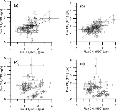
Emissions determined from the FID/SOPS measurement system were the best estimate of hourly source area emissions. All path combinations resulted in mean emissions over the 13 days of measurements within a confidence interval of 90%. A comparison of individual hourly emissions determined using the FID/SOPS system and the complete TDL/OP system (schemes 2 and 9) for the measurements along the north and west sides of the lagoon indicated wide variability (). In general, the variability in emissions based on the FID/SOPS system (SD = 45 μg m−2 sec−1) was greater than those using TDL/OP schemes 2 and 9 (SD = 30 and 31 μg m−2 sec−1, respectively). The difference in variability was likely due to the integration time of the measurements, since the comparison between comparable FID/SOPS concentration (taken at 28–30 and 43–45 min after the hour) and TDL/OP concentration measurements (taken for 10 sec each every approximately 5 min) showed substantial variability (standard deviation) of 4.77 μL L−1 along the west side and 2.71 μL L−1 along the north side. Under stable conditions, the emissions determined using the TDL/OP system for each side were correlated but biased high compared with that determined using the FID/SOPS system (, ). Segmenting the measured TDL/OP (scheme 9) resulted in a higher correlation with the FID/SOPS system emission estimate (r = 0.55) than using the original OP measurements (r = 0.48). Under unstable conditions, the emissions determined by the two TDL/OP schemes were not correlated (, ). The lack of correlation of the emissions determined using the two measurement systems under unstable conditions suggests that the small differences in integration path location and length on the north and west sides of the lagoon were leading to measurement of regions of the lagoon with different source strengths (Lehning et al., Citation1994). The greater correlation of emissions under stable conditions compared with unstable conditions suggests that stable conditions tend to horizontally homogenize the CH4 within the lagoon berms prior to being measured across the berm.
Figure 9. Comparison of CH4 emission estimates based on the TDL/OP and FID/SOPS concentration measurements. Emissions based on concentration measurements made for TDL/OP schemes 2 and 9 under stable conditions (a and b, respectively) and under unstable conditions (c and d, respectively). Error bars represent the 95% confidence interval of the estimate. Solid lines indicate a linear regression through the origin.
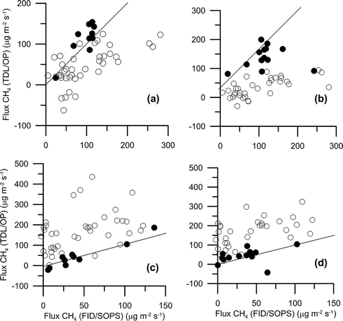
The lagoon source area was partitioned into two distinct adjacent sources (northern one-third and southern two-thirds of the lagoon) based on the previously discussed large deviation of the concentration along OP 8 under north and east winds from that expected assuming a homogeneous source (). This has a physical basis in that (1) the emissions might be expected to be higher with fresh manure deposited into the lagoon from the waste inlets on the north side of the lagoon (); (2) inconsistency of cross-lagoon PIC for the northernmost OP under northerly winds (); and (3) higher FID/SOPS Cbg estimates and reduced single-source zone emissions under northerly winds (). The FID/SOPS-based emissions calculated for the northern source region near the inlets were generally greater than those for the southern bulk of the lagoon (). Emissions from the northern portion of the lagoon averaged 99 μg m−2 sec−1 (SD = 79 μg m−2 sec−1), whereas that from the southern portion averaged 41 μg m−2 sec−1 (SD 50 = μg m−2 sec−1). The CV of the two-zone lagoon source was greater than that for the single-source zone. The CV of the northerly region (0.79) was less than that of the southerly region (1.20), suggesting that emissions from the continuous addition of fresh manure from the milking parlor and holding area at the inlet pipe provided a more stable emission than the ebullition events associated with CH4 production in the sludge at the lagoon bottom. The increased variability in the emission estimates with the partitioning of the sources over that for the lagoon as a whole is likely a result of the lack of influence of the inhomogeneous source on the cross-lagoon concentrations for most wind directions (). The 90th percentiles of the hourly emissions for the northern and southern regions of the lagoon were 174 and 103 μg m−2 sec−1, respectively. The mean total lagoon CH4 emissions for the two-source-region lagoon using the FID/SOPS system was 63 μg m−2 sec−1 (0.020 kg day−1 hd−1), 57% lower than the emissions assuming a single homogeneous source (). Prior studies indicate that although component emission rates of adjacent sources may be inaccurate, the total combined emission rate determined using the bLS model is excellent (100% recovery) (Gao et al., Citation2008). Consequently, the lower overall lagoon emission rate was likely more accurate than that obtained from the assumed single homogeneous source.
The total lagoon emissions for a two-zone source were evaluated for TDL/OP schemes 2 and 9. Fewer measurement periods were valid for the two-zone source, since valid emissions calculations for both regions within the lagoon were possible only when winds were from the southeast to south (). The determined Cbg for the two-source configuration did not differ greatly from the one-source configuration (). Again, the substantial differences between the bLS-calculated Cbg and the minimum FID/SOPS concentration for wind directions of 100°–225° resulted in the exclusion of these wind directions from analysis (). As with the FID/SOPS emissions, the emissions for these two TDL/OP schemes were greatly reduced by partitioning the lagoon into two source regions (). The segmented OPs of scheme 9 better approximated the emissions determined by FID/SOPS (). Also, as with the FID/SOPS emissions, the emissions from the northern region were greater than those from the southern region: mean emissions from the northern source were 120.9 and 128.2 μg m−2 sec−1 for TDL schemes 2 and 9, respectively, whereas those for the southern source were 32.9 and 41.2 μg m−2 sec−1 for TDL schemes 2 and 9, respectively.
In general, TDL/OP scheme 2 was a better approximation of the FID/SOPS-measured emissions from a two-source area lagoon () than scheme 9. The emissions derived from scheme 2 for the lagoon as a whole were not significantly different from the FID/SOPS measurement method (10 paired values at α = 0.05), whereas those for scheme 9 were significantly different (13 paired values). The scheme 2 TDL/OP emissions for the northern source region (near the lagoon inlets) were significantly different from the FID/SOPS emissions (t = 2.51), but not significantly different for scheme 9 (13 paired values at α = 0.05). There was no significant difference (α = 0.05) in the determined emissions for the southern region (bulk of the lagoon) between those derived using either TDL/OP scheme or the FID/SOPS-measured emissions.
Figure 10. Comparative CH4 emissions from the two source regions within the lagoon. The comparison of emissions from the north (a and b) and south (c and d) source regions of the lagoon based on the FID/SOPS measurement system and TDL/OP scheme 2 (b, d) and TDL/OP scheme 9 (a, c) are indicated. Solid circles correspond to emissions with winds from southeast to south (wind directions of 85°–190°). Solid lines represent 1:1 relationship.
Summary and Conclusion
The bLS estimation of the emission rate of a gas with a measurable background concentration relies heavily on the determination of the background concentration from at least one optical path. Consequently, gases with a measurable background concentration require at least two optical paths. If the gas being studied does not have a measurable background concentration or has a known value, estimation of the emissions can be done with only one path.
For gases with a significant background concentration such as CH4, estimates of the background concentration are critical. Measurement paths upwind from the source or out of the source plume are needed. The greatest impact of additional paths on emission estimation is reduction of the emission confidence interval through an increase in the touchdown fraction in the source. Segmenting the scanned OP increased the number of valid emission measurements by providing more opportunities for an OP to be outside of the source plume and improved the emission estimate. The nonhomogeneity of the emission source was evidenced by the inconsistent emission estimation for OP smaller than the source diameter, the variation in PIC across the lagoon with changes in wind direction, and the reduced accuracy of emission estimates under unstable atmospheric conditions.
The partitioning of the lagoon source into two source regions decreased the calculated CH4 emissions by 57%, but increased the variation around the mean. Consequently, CH4 emissions calculated using inverse disperse models under the assumption that the lagoon is a uniform source are likely to be overestimates due to the spatially and temporally discrete nature of the CH4 emissions. Other gases with similar poor solubility in water may also require partitioning of the lagoon source area.
Funding
This project was supported by the Dairy Research Incorporated and the Purdue Agricultural Research Station and is paper #1602 of the Purdue Climate Change Research Center.
Acknowledgment
The authors thank the extensive field help from Jenafer Wolf, Alfred Lawrence, Scott Cortus, Benjamin Evans, Chris Fullerton, Derrick Snyder, Hans Schmitz, and Gianna Hartman.
Additional information
Notes on contributors
Richard H. Grant
Richard H. Grant is professor of agro-micrometeorology in the Department of Agronomy, Purdue University.
Matthew T. Boehm
Matthew T. Boehm was a postdoctoral fellow in the Department of Agronomy, Purdue University, during the study and is currently a software engineer with Lafayette Instrument Company.
References
- Bjorneberg, D.L., A.B. Leytem, D.T. Westermann, P.R. Griffiths, L. Shao, and M.J. Pollard. 2009. Measurement of atmospheric ammonia, methane, and nitrous oxide at a concentrated dairy production facility in southern Idaho using open-path FTIR spectroscopy. Trans. ASABE 52:1749–1756. doi:10.13031/2013.29137
- Casey, K.D., J.R. Bicudo, D.R. Schmidt, A. Singh, S.W. Gay, R.S. Gates, L.D. Jacobson, and S.J. Hoff. 2006. Air quality and emissions from livestock and poultry production/waste management systems. In Animal Agriculture and the Environment: National Center for Manure and Animal Waste Management White Papers, ed. J.M. Rice, D.F. Caldwell, and F.J. Humenik, 1–40. ASABE Publication 913C0306. St. Joseph, MI: American Association of Agricultural and Biological Engineers.
- Flesch, T.K., J.D. Wilson, L.A. Harper, B.P. Crenna, and R.P. Sharpe. 2004. Deducing ground-to-air emissions from observed trace gas concentrations: A field trial. J. Appl. Meteorol. 43:487–502. doi:10.1175/1520-0450(2004)043%3C0487:DGEFOT%3E2.0.CO;2
- Gao, Z., R.L. Desjardins, R.P. vanHaarlem, and T.K. Flesch. 2008. Estimating gas emissions from multiple sources using a backward Lagrangian Stochastic Model. J. Air Waste Manage. Assoc. 58:1415–1421. doi:10.3155/1047-3289.58.11.1415
- Grant, R.H., and M.T. Boehm. 2010. National Air Emissions Monitoring Study: Data from the eastern US milk production facility IN5A. Final Report to the Agricultural Air Research Council. Purdue University, West Lafayette, Indiana. http://www.epa.gov/airquality/agmonitoring/in5a.html ( accessed January 3, 2013).
- Lehning, M., D.R. Shonnard, D.P.Y. Chang, and R.L. Bell. 1994. An inversion algorithm for determining area-source emissions from downwind concentration measurements. J. Air Waste Manage. Assoc. 44:1204–1213. doi:10.1080/10473289.1994.10467315
- Leytem, A.B., R.S. Dungan, D.L. Bjorneberg, and A.C. Koehn. 2010. Emissions of ammonia, methane, carbon dioxide, and nitrous oxide from dairy cattle housing and manure management systems. J. Environ. Qual. 40:1383–1394. doi:10.2134/jeq2009.0515
- Ni, J.-Q., A.J. Heber, A.L. Sutton, and D.T. Kelly. 2009. Mechanisms of gas releases from swine wastes. Trans. ASABE 52:2013–2025.
- Todd, L.A., M. Ramanathan, K. Mottus, R. Katz, A. Dodson, and G. Mihlan. 2001. Measuring chemical emissions using open-path Fourier transform infrared (OP-FTIR) spectroscopy and computer-assisted tomography; Atmos. Environ. 35: 1937–1947. doi:10.1016/S1352-2310(00)00546-X
- U.S. Environmental Protection Agency. 2014. Inventory of U.S. Greenhouse Gas Emissions and Sinks: 1990–2012. EPA 430-R-14-003. Washington, DC: U.S. Government Printing Office.
- Varadharajan, C.V., and H.F. Hemond. 2012. Time series analysis of high-resolution ebullition fluxes from a stratified, freshwater lake. J. Geophys. Res. 117:G02004. doi:10.1029/2011JG001866