
ABSTRACT
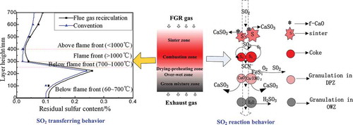
The primary goal of this paper is to reveal the reaction behavior of SO2 in the sinter zone, combustion zone, drying–preheating zone, and over-wet zone during flue gas recirculation (FGR) technique. The results showed that SO2 retention in the sinter zone was associated with free-CaO in the form of CaSO3/CaSO4, and the SO2 adsorption reached a maximum under 900ºC. SO2 in the flue gas came almost from the combustion zone. One reaction behavior was the oxidation of sulfur in the sintering mix when the temperature was between 800 and 1000ºC; the other behavior was the decomposition of sulfite/sulfate when the temperature was over 1000ºC. However, the SO2 adsorption in the sintering bed mainly occurred in the drying–preheating zone, adsorbed by CaCO3, Ca(OH)2, and CaO. When the SO2 adsorption reaction in the drying–preheating zone reached equilibrium, the excess SO2 gas continued to migrate to the over-wet zone and was then absorbed by Ca(OH)2 and H2O. The emission rising point of SO2 moved forward in combustion zone, and the concentration of SO2 emissions significantly increased in the case of flue gas recirculation (FGR) technique.
Implications: Aiming for the reuse of the sensible heat and a reduction in exhaust gas emission, the FGR technique is proposed in the iron ore sintering process. When using the FGR technique, SO2 emission in exhaust gas gets changed. In practice, the application of the FGR technique in a sinter plant should be cooperative with the flue gas desulfurization (FGD) technique. Thus, it is necessary to study the influence of the FGR technique on SO2 emissions because it will directly influence the demand and design of the FGD system.
Introduction
The removal of combustion gases has been the subject of many studies in recent years because these pollutants cause environmental problems (Sun et al., Citation2010). SO2 emissions from industrial processes are the main cause of acid rain, which is destructive to the ecological environment and causes issues such as aquatic ecosystem damage, soil acidification, and materials corrosion, among others. SO2 emissions represent a grave threat to human survival (Hao et al., Citation2000; Su et al., Citation2011). More than 11% of the total Chinese SO2 emissions come from the iron and steel industry, wherein the sintering process accounts for more than 60% of the emissions (Zhu et al., Citation2014). The process of flue gas desulfurization (FGD) has become one of the greatest challenges in industrial processes because of the serious environmental pollution caused by SO2. During the sintering process, the solid fuel in the mixture on the top of the bed is first ignited; from this point onward air is sucked down through the bed. The air is first preheated by its passage through the upper sinter zone, then sustains combustion of the hot carbon, and finally is rapidly cooled by evaporating the water from the bed immediately below the combustion zone. The gas leaves the bed and passes as waste gas into the fan. The concentration of SO2 emissions in a sinter plant is normally between 200 and 1000 g/t-sinter, which corresponds to the average waste gas emissions concentration of 95 to 480 mg/Nm3, based on the waste gas flow of 2100 N-m3/t-sinter (Mao et al., Citation2013; Zong et al., Citation2009; Kasama et al., Citation2006). FGD techniques are currently applied widely in power plants, such as wet flue gas desulfurization, dry flue gas desulfurization, and semidry flue gas desulfurization (Srivastava et al., Citation2001; Richter, Citation1980; Werther, Citation2007). Due to the characteristics of exhaust gas, such as high gas flow rate, high gas temperature, and dust, problems still exist in the application of FGD techniques in the sintering process, including heavy investment, high running cost, and useless by-products (Xu et al., Citation2000; Schoenberger, Citation2000; Alexander, Citation2006).
Aiming for the reuse of the sensible heat and a reduction in the cost of end-of-pipe cleaning techniques, the flue gas recirculation (FGR) technique was proposed in the 1990s, and it was developed based on the principle that portions of the waste gases are recycled to the sintering bed (Rainer et al., Citation2013). When using the FGR technique, the gas flow passing through the sintering bed changes from air to FGR gas. Differing from NOx, SO2 is difficult to reduce but is absorbed by the sintering bed, which leads to an increase in the sulfur content in the sinter. Meanwhile, the emission rising point of SO2 moves forward, and the concentration of SO2 emissions significantly increases in the case of FGR. In practice, the application of the FGR technique in a sinter plant should be cooperative with the FGD technique. Thus, it is necessary to study the influence of the FGR technique on SO2 emissions because it will directly influence the demand and design of the FGD system.
Li et al. conducted research studies on SO2 adsorption by the raw material and found that the moisture and CaO in the raw material were the main factors affecting SO2 adsorption in sintering process (Li et al., Citation2014). However, the sintering bed is made up of several zones instead of raw material during the sintering process, and the reaction behaviors of SO2 in the different zones in the case of FGR still suffer from the lack of research studies. In this paper, the sintering bed is divided into the sinter zone, the combustion zone, the drying–preheating zone, the over-wet zone, and the green mixture zone, based on the temperature and physical and chemical reactions. When using the FGR technique, a gas flow of SO2 is successively passed through these zones during the sintering process. The migration model of SO2 in the sintering bed will be built by determining the reaction behaviors of SO2 in the different sintering conditions. The model provides a theoretical basis for the design of the material layer structure and contributes to the reduction of SO2 in FGR sintering.
Materials and methods
Raw material
Iron ore blending, fuels, and fluxes (including dolomite, limestone, and quicklime) were utilized to produce sinter with total Fe (TFe) 58.11%, SiO2 4.88%, basicity (R = CaO/SiO2) 1.85, and MgO 1.60%. The chemical compositions of raw materials and their mass fractions are given in . The proximate analysis of coke breeze and chemical composition of its ash are shown in . The fixed carbon content was 82.72%, while the sulfur content was 0.78%. shows the compositions of the sinter, which was set as the sample in the simulation test of SO2 reaction behavior in the sinter zone in the small-scale shaft furnace. The TFe content in sinter was 58.35% while CaO content was 9.03%; especially, the content of free CaO (f-CaO) was 1.64% and residual sulfur content was 0.0075%.
Table 1. Chemical composition of raw materials and their percentages in mixture, wt%.
Table 2. Proximate analysis of coke breeze, wt%.
Table 3. Chemical composition and residual sulfur content of sinter, wt%.
The chemical compositions of raw materials and sinter were detected and analyzed according to the national standard (GB/T 6730). TFe, FeO, CaO, MgO, Al2O3, and S contents of the raw materials and sinter were detected by using a capacity assay method, while SiO2 and LOI contents of raw materials and sinter were detected by using a gravimetric method. The proximate analysis of coke breeze was analyzed according to the national standard (GB/T 28731-2012)
Experimental setup and procedures
FGR technique
The components of FGR gas were calculated based on the principles of the exhaust gas emission rule and mass balance. The principles included the following:
Qcir (gas required for the FGR process) was determined according to the equation Ccir · Qcir = Qair · Cair. Qair (gas required for the conventional process) was ascertained by tests, while Cair (the heat capacity of air) and Ccir (the heat capacity of FGR gas) are known physical quantities related to the properties of gas. If the amount of FGR gas could not reach Qcir, then the short part was made up with hot cooling gas.
The consumption of O2 and the production of CO2 and H2O(g) during FGR process were calculated according to the carbon, H2O, FeO, and carbonate contents of the sintering mixture.
It was assumed that CO in the inlet gas was completely combusted during the FGR process. The gas temperature was controlled by regulating the hot cooling gas if it is lower than 250ºC.
shows the flow diagram of the sintering process with FGR. The sintering machine was divided into five parts: I, II, III, IV and V, which represented ignition, sintering, rising gas temperature, desulfurization, and cooling, respectively. Based on the influencing mechanism of the FGR gas properties on the sintering process, a feasible FGR technology with the appropriate properties of the flue gas was proposed. The FGR gas was made up with 35 vol% from II and 100 vol% from V, which accounted for 35.5 vol% of the exhaust gas. The exhaust gas from IV, which had a high SO2 content, was directly introduced into the desulfurization system, while 100 vol% from I, 100 vol% from III, and 65 vol% from II were introduced into the main gas duct. The gas temperature in the main gas duct was above the acid dew point because of the high-temperature gas from III.
Figure 1. Flow diagram of sintering process with FGR.
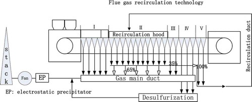
shows the properties of the FGR gas in the case of a 35.5 vol% FGR ratio. The gas temperature was controlled at 250ºC; the O2 content in the FGR gas was 17%, while the CO content in the FGR gas was 0.52%. Meanwhile, the CO2 and H2O(g) contents in the FGR gas were 4.0% and 4.9%, respectively. The SO2 content in the FGR gas was 0.045% (450 ppm).
Table 4. Properties of circulating flue gas.
The effects of the FGR technique on the sinter indices and the SO2 emission were studied in sintering pot tests. The sinter indices included VSV (vertical sintering velocity), P (productivity), Y (yield), and TI (tumble index). The methods and a schematic diagram of the sintering pot tests can be found in the relevant literature, while SO2 emissions in exhaust gas were detected with a flue gas analyzer (Fan et al., Citation2014). The measurement principle of the SO2 gas analysis was based on nondispersive infrared (NDIR) technology. The sulfur retentions in the sintering mixture, sinter, and return fines were detected using an HCS 140 high-frequency infrared ray carbon sulfur analyzer to calculate the sulfur balance.
Simulation of the sintering bed
When flue gas was recirculated to the sintering bed, it successively passed through the sinter zone, the combustion zone, the drying–preheating zone, the over-wet zone, and the green mixture zone. The five zones were divided based on the temperature and physical and chemical reactions to simulate the sintering process; the basic characteristics of each zone are described in .
Table 5. Basic characteristics of each zone.
The reaction behaviors of SO2 in the sintering bed were investigated in a quartz fixed-bed reactor that was 10 mm in diameter and 50 mm in height; the schematic diagram of the sintering apparatus is shown in . The experiments proceeded as follows: 40 g of sinter (used to simulate sinter zone) or raw material granulated mixture (used to simulate combustion zone and dried in advance) was charged into the charging cup. The granulated mixture came from the granulation, of which the particle size was 5–8 mm and the moisture was 8%, while the sinter sample was the final product of sinter pot test. However, the adsorption process in the over-wet zone was carried out with the granulated mixture of 10% moisture. Next, the preheating temperature of each zone was set as described in . Simultaneously, special content standard gases (O2, CO, CO2, SO2, and Ar) were introduced into the charging cup after mixing, and then the gas velocity was kept constant at 18 m/min. The compositions in the outlet gas were detected via a gas analyzer during the heating period. The main phases of sulfur in the samples before and after the test were investigated using chemical phase analysis, which was based on the difference of the solubility and dissolution rates of various minerals in a chemical solvent to measure the contents in the form of the various mineral elements (Zhang, Citation2006). The free CaO content in the samples was determined according to the national standard (GB/T176-2008) (Zhang, Citation2006; Zhang, Citation2010).
Figure 2. Schematic diagram of sinter zone simulation (1 gas, 2 valve, 3 flowmeter, 4 mixing box, 5 thermocouple, 6 electronic balance, 7 computer, 8 temperature controller, 9 quartz tube, 10 charging cup, 11 shaft furnace, 12 dryer, 13 gas analyzer).
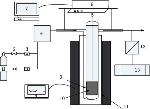
shows the details of the gas condition of each zone for the simulation of the sintering atmosphere in the case of the FGR process. The temperature of the sinter zone varied from 500 to 1100ºC, with an atmosphere of 16% O2, 0.4% CO, 4% CO2, and 450/800 ppm SO2 when studying the SO2 adsorption in the sinter. The SO2 release behavior within the different temperature combustion zones in the case of air or FGR gas was studied, and the FGR gas consisted of 16% O2, 4.5% CO2 and 450 ppm SO2. Due to fuel combustion, the atmosphere in the drying–preheating zone significantly changed to 6% O2, 0.8% CO, 15% CO2, and 450/800 ppm SO2, which was the same as that in the over-wet zone. The remaining gas flow was Ar.
Table 6. Experimental conditions of each zone in detail.
Results
The FGR gas passed through the sintering bed when the sintering process reached at II. The upper sinter zone had been formed after finishing the ignition, while the combustion zone transferred down under the suck pressure. Therefore, when the FGR gas was recirculated to the sintering bed, SO2 passed through the sinter zone, the combustion zone, the drying–preheating zone, the over-wet zone, and the green mixture zone, successively.
Reaction behavior of SO2 in the sinter zone
shows the influence of the sinter temperature on the reaction behavior of SO2 in the sinter zone. The SO2 content in the outlet gas rapidly decreased with the increase of sinter temperature; that is, SO2 adsorption occurred in the hot sinter. As the adsorption proceeded, the SO2 adsorption in the sinter was enhanced as the sinter temperature increased from 500ºC to 900ºC. However, a higher sinter temperature resulted in a reduction in SO2 adsorption due to the decompositions of the sulfur retention products (CaSO3 or CaSO4) when the temperature exceeded 1000ºC. As the f-CaO content in the sinter was 1.64% and the SO2 content in the FGR gas was 450 ppm, the SO2 adsorbing agents were abundant. Thus, the SO2 adsorption in the sinter zone lasted long and the SO2 contents in the outlet gas did not tend to reach its initial value after adsorbing 15 min.
Figure 3. Influence of sinter temperature on SO2 adsorption in the sinter zone.
shows the sulfur content in the sinter after SO2 adsorption for 15 min at different temperatures. The sulfur content was increased with the increase in the SO2 content in the circulating flue gas, especially when the sinter temperature was 900ºC. When the SO2 content in the circulating flue gas was 800 ppm, the sulfur content increased from 0.024% to 0.053% (at 900ºC).
Figure 4. Sulfur content in the sinter zone after adsorbing for 10 min at different temperatures.
The SO2 adsorption above the flame front occurs as the existence of f-CaO in the sinter. shows the influence of the f-CaO content on the SO2 retention in the sinter zone at 900ºC. With the increase of f-CaO content, the SO2 content in the outlet gas decreased. When the f-CaO content was 5%, the SO2 retention in the sinter was significantly enhanced, and the SO2 content decreased from 450 ppm to 304 ppm. The reason for this behavior is that sulfur oxides (SOx) can significantly react with f-CaO in the form of CaO + SO2 = CaSO3 and 2CaO + 2SO2 + O2 = 2CaSO4. Therefore, the f-CaO content in the sinter above the flame front should be controlled to reduce the SO2 adsorption when the FGR technique is used.
Figure 5. Influence of f-CaO content on SO2 reaction behavior in the sinter zone.
Reaction behavior of SO2 in the combustion zone
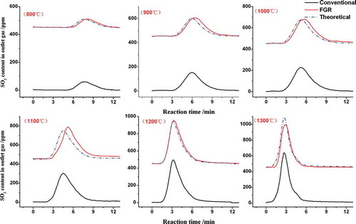
shows the comparisons of SO2 release in the combustion zone between the conventional and FGR techniques under different temperatures. shows three lines: Conventional, FGR, and Theoretical. The Conventional and FGR lines respectively represent the SO2 emission concentration in the air and FGR gas, while the Theoretical line represents the sum of the SO2 contents in the circulating flue gas and the Conventional technique. The SO2 gas began to release into the outlet gas when the temperature of the combustion zone reached 800ºC. The emission rising point of SO2 moved forward, and the emission peak of SO2 significantly increased as the temperature increased. SO2 in the outlet gas mainly originated from the oxidation of sulfide and organic sulfur in the sintering mixture in the temperature range of 800–1000ºC. When the temperature exceeded 1100ºC, the SO2 concentration in the outlet gas increased because of the decomposition of the sulfite or the sulfate in the sintering mixture. According to the Theoretical lines at 1300ºC, the rate of SO2 removal slightly decreased when FGR technique was used.
Figure 6. Comparison of SO2 emission between conventional and FGR processes in the combustion zone.
Reaction behavior of SO2 in the drying–preheating zone
The SO2 adsorption below the flame front in the sintering bed almost occurs in the drying–preheating zone, where the dynamic condition is favored due to the abundance of SO2 absorbent and the appropriate temperature. The main adsorption reactions that possibly occur are as follows, but similar reactions will take place with MgO that is in smaller amounts in the drying–preheating zone. The delta G and T in reactions (1) to (6) respectively represent the Gibbs free energy and temperature, of which the unit respectively is J and K.
shows the influences of temperature and SO2 content on the sulfur content in the drying–preheating zone. The sulfur content in the drying–preheating zone increased with the increases of temperature and SO2 content in the FGR gas. The temperature had the key role in SO2 adsorption because the main kinetic parameter of SO2 adsorption is a chemical reaction in the drying–preheating zone. When the mixture temperature was 100ºC, the sulfur content of the sintering mixture increased from 0.123% to 0.141%; however, the sulfur content increased from 0.121% to 0.230% when the temperature increased to 700ºC.
Figure 7. Influence of SO2 content and temperature on sulfur content in the drying–preheating zone.
Reaction behavior of SO2 in the over-wet zone
After the SO2 adsorption in the drying–preheating zone, the excess SO2 gas continued to migrate to the over-wet zone. shows the effects of the SO2 content in the FGR gas on the SO2 adsorption in the over-wet zones with different thicknesses. When the SO2 content was 450 ppm, the sulfur content of the over-wet zone was increased from 0.121% to 0.210% as the thickness of over-wet zone increased to 50 mm. However, the sulfur content in the over-wet zone increased to 0.252% when the SO2 content was 800 ppm. The SO2 adsorption behavior in the over-wet zone was the same as that in the drying–preheating zone.
Figure 8. Influence of SO2 content on sulfur content in the over-wet zones with different thickness.
Discussion
The transferring behavior of SO2 in the sintering bed was found to be clearly affected by the FGR technique, as detected by measuring the sulfur distribution of the sintering bed. The experimental procedure of sulfur distribution was conducted as follows: During the conventional technique, the suck fan was shut down after sintering for 15 min, breaking off the sintering pot test by rapidly cooling with liquid nitrogen. In the case of FGR technique, the FGR hood was first added on the top of sinter pot after ignition, and then the hood was removed when the sintering time was 15 min. Then the samples were taken every other 100 mm from the pot and the sulfur content of each sample was determined. As shown in , compared with the conventional technique, the sulfur contents of the different layers were higher because of the existence of SO2 in the FGR gas, especially in the sinter zone and the drying–preheating zone. As the results of the research already described, the FGR gas of SO2 gas will react with CaO above the flame front (<1000ºC) if there is some f-CaO in the sinter, which leads to an increase in the residual sulfur; subsequently, the FGR gas goes through the flame front (≥1000ºC) where SO2 is significantly generated by the decompositions of CaSO3 and CaSO4; the SO2 generation continues below the flame front (700 < T < 1000ºC) because of the oxidation of sulfide and organic sulfur; and these sources of SO2 generation will be slightly inhibited because the SO2 partial pressure in the FGR gas increases. SO2 from above the sintering bed will easily react with CaO/CaCO3/Ca(OH)2 to form CaSO3/CaSO4 at low temperature (<700ºC). The content of sulfate products will increase because of the existence of SO2 in the FGR gas.
Figure 9. Influence of FGR on SO2 transferring behavior.
presents a comparison of the sulfur phase in the sinter samples before and after the SO2 adsorption at temperatures of 900ºC. Compared with the conventional technique, the total sulfur content in the sinter increased due to the increases of SO2 in the FGR gas and the f-CaO content in the sinter. In addition, the sulfur phase in the sinter was almost exclusively in the form of sulfate (SO42-).
Table 7. Comparison of sulfur phase in the sinter sample before and after SO2 adsorption at 900ºC.
Fuel combustion plays a key role in the combustion zone, where SO2 is formed by the oxidation of sulfide and organic sulfur below the flame front. However, the sulfur partition (Ssinter/Sgas) of the combustion zone gets changed in the case of FGR technique since the SO2 formation is inhibited because of the low oxygen partial pressure and the existence of SO2 gas. The influence of the SO2 content on the sulfur outputs at 1300ºC was studied, and the results are presented in . With the increase of sulfur inputs, the SO2 emission (the total amount and peak value) and the residual sulfur in the granules increased. The sulfur partition increased with the existence of SO2 in the FGR gas. Therefore, the SO2 content in the circulating flue gas must be considered, as an excess of SO2 gas (over 800 ppm) will introduce adverse effects on the sinter indices and the sulfur partition.
Table 8. Sulfur balance of granules in the combustion zone at 1300ºC.
The SO2 gas comes from the FGR gas and the formation in the combustion zone will be absorbed at the unsintered zones (including drying–preheating, over-wet, and green mixture zones). shows the results of the sulfur phase analysis in the unsintered zones. The results show that sulfur retention in the sintering mixture increased due to the existence of SO2 in the FGR gas. Compared to a mixture with no CaO content, SO2 adsorption in a mixture comprising 8.11% CaO significantly increased in the form of 2SO2 + O2 + 2CaO = 2CaSO4. The sulfur phase was also in the form of sulfate. The SO2 adsorption reaction easily reaches the equilibrium; simultaneously, the SO2 retention in the unsintered zone releases again as long as the temperature of the sintering bed increases.
Table 9. Comparison of sulfur phase in the unsintered zone before and after SO2 absorption.
shows the thermodynamic curve of the sulfur retention behavior in the unsintered zones. As the temperature of the unsintered zones varies in the range of 50–700ºC, the SO2 in the FGR gas was significantly adsorbed according to reactions (1), (2), (3), (4), (5), and (6). Among these pathways, reactions (3), (5), and (6) play leading roles in sulfur adsorption in the sintering bed. The FGR gas passing through the unsintered zone first reaches the drying–preheating zone, where the CaO and CaCO3 contents are much higher than the Ca(OH)2 and H2O since decomposition of Ca(OH)2 and evaporation of H2O significantly occur. After the SO2 adsorption in the drying–preheating zone, the excess SO2 gas then arrives at the over-wet zone to be adsorbed.
Figure 10. Thermodynamic curve of sulfur retention behavior in unsintered zone.
The novel FGR technique is proposed based on the consideration of waste heat utilization and the sinter indices. Thus, the sinter indices of the FGR technique are found to nearly match those of the conventional technique and qualified to the feed of blast furnace. However, the SO2 emission in the exhaust gas changed, for example, the SO2 emissions peak and region. presents a comparison of the SO2 emissions in the exhaust gas between the conventional and FGR techniques under the sinter pot test. The SO2 emission curve of the sintering process hardly changed, whereas the SO2 emission region significantly changed. Due to the increase of SO2 retention in unsintered zone, the SO2 emission rising point moved forward, and the concentration of SO2 emissions significantly increased in the case of FGR. It is quite significant to consider the SO2 emission rule in the case of FGR because it can determine the demand and design of the FGD technique, such as the region selection and amount of flue gas desulfurization.
Figure 11. Comparison of SO2 emission in exhaust gas between conventional and FGR techniques.
shows the results of the sulfur balance of the sintering process in the case of air and FGR gas. As shown in , the main sulfur outputs corresponded to the SO2 emission in the exhaust gas, with the sulfur partition of approximately 0.15. As the FGR gas of SO2 passed through the sintering bed, the sulfur outputs in the exhaust gas increased, which corresponded to the SO2 emission in the exhaust gas. Meanwhile, the sulfur retention in the sinter products (sinter and return fines) increased owing to the SO2 adsorption in the sinter zone, and the sulfur retention in the return fines was more significant. The sulfur partition increased from 0.13 to 0.18; that is, the sulfur adsorption in sintering bed performed as expected.
Table 10. Sulfur balance of sintering process in the case of air and FGR gas.
Conclusions
SO2 retention in the sinter zone is associated with f-CaO in the form of CaSO3/CaSO4. When the temperature of the sinter increases to 500ºC, the amount of SO2 absorbed by CaO begins to increase and reach a maximum at 900ºC. With the further increase of the sinter temperature, the amount of SO2 absorption is reduced because the decomposition of CaSO3 occurs at a higher temperature (>1000ºC).
SO2 in the flue gas almost exclusively originates from the combustion zone and consists of two parts. One part is the oxidation of sulfide and organic sulfur in the sintering mixture when the temperature between 800 and 1000ºC; the other part is the decomposition of sulfite/sulfate when the temperature is over 1000ºC. The oxidation of sulfur and the decomposition reaction are inhibited by the decrease in O2 partial pressure and the increase in SO2 partial pressure in the case of the FGR technique.
The sulfurous acid (H2SO3) formed in the over-wet zone is decomposed to SO2 during the drying and preheating process; however, SO2 adsorption mainly occurs in the drying–preheating zone. The SO2 originates from the combustion zone, and sulfurous acid decomposition will significantly react with absorbents in the drying–preheating zone in the forms of 2SO2 + 2CaCO3 + O2 = 2CaSO4 + 2CO2, SO2 + CaCO3 = CaSO3 + CO2, 2SO2 + 2Ca(OH)2 + O2 = 2CaSO4 + 2H2O, SO2 + CaO = CaSO3, and 2SO2 + O2 + 2CaO = 2CaSO4.
With SO2 content increases in the FGR gas, the SO2 adsorption reaction easily reaches equilibrium. Thus, the excess SO2 gas will continue to migrate to the over-wet zone and be absorbed by the Ca(OH)2 and H2O in the forms of 2SO2 + 2Ca(OH)2 + O2 = 2CaSO4 + 2H2O and 2SO2 + 2H2O + O2 = 2H2SO4.
A novel sintering of 35.5 vol% FGR ratio was proposed, based on the consideration of waste heat utilization and sinter indices. The sinter indices of the FGR technique are essentially consistent with those of the conventional technique. However, the emission rising point of SO2 moves forward, and the concentration of SO2 emissions significantly increases in the case of FGR. These changes directly influence the demand and design of FGD system.
Funding
The research is financially supported by the National Natural Science Foundation of China (number 51304245), the 2014 Hunan Provincial Innovation Foundation for Postgraduate (CX2014B094), the Hunan Provincial Co-Innovation Center for Clean and Efficient Utilization of Strategic Metal Mineral Resources, and an outstanding and creative doctor scholarship of Central South University (2013bjjxj015).
Additional information
Funding
Notes on contributors
Zhi-yuan Yu
Zhi-yuan Yu is a Ph.D. researching on the new technology in the agglomeration and energy saving and pollutants reduction in the metallurgical engineering.
Xiao-hui Fan
Zhi-yuan Yu is a Ph.D. researching on the new technology in the agglomeration and energy saving and pollutants reduction in the metallurgical engineering.
Xiao-hui Fan is a professor engaged in research on sintering and pelletizing theory and new technology.
Min Gan
Min Gan is an assistant professor, researching on the sintering and pelletizing theory and comprehensive utilization of mineral resources.
Xu-ling Chen
Xu-ling Chen is an assistant professor, researching on the sintering and pelletizing theory and process optimization control in the iron-making process.
Qiang Chen
Qiang Chen and Yun-song Huang are postgraduates, researching on the new technology in the iron ore sintering process.
References
- Alexander, D. F. 2006. Improved dry type gas cleaning process for the treatment of sinter off-gas. Metallurgical Plant Technol. Int. 3:36–40.
- Fan, X.H., Z.Y. Yu, M. Gan, X.L. Chen, T. Jiang, and H.L. Wen. 2014. Appropriate technology parameters of iron ore sintering process with flue gas recirculation. ISIJ Int. 54(11): 2541–50. doi:10.2355/isijinternational.54.2541
- Hao, J.M., S.X. Wang, B.J. Liu, and K.B. He. 2000. Designation of acid rain and SO2 control zones and control policies in China. J. Environ. Sci. Health Part A Toxic/Hazard. Subst. Environ. Eng. 35:1901. doi:10.1080/10934520009377085
- Kasama, S., H. Kitaguchi, and Y. Yamamura. 2006. Analysis of exhaust gas visibility in iron ore sintering plant. ISIJ Int. 46(7): 1027–32. doi:10.2355/isijinternational.46.1027
- Li, G. H., C. Liu, M.J. Rao, Z.Y. Fan, Z.X. You, Y.B. Zhang, and T. Jiang. 2014. Behavior of SO2 in the process of flue gas circulation sintering (FGCS) for iron ores. ISIJ Int. 54(1): 37–42. doi:10.2355/isijinternational.54.37
- Mao, X.Q., A. Zeng, T. Hu, J. Zhou, Y.K. Xing, and S.Q. Liu. 2013. Co-control of local air pollutants and CO2 in the Chinese iron and steel industry. Environ. Sci. Technol. 47:12002−10. doi:10.1021/es4021316
- Rainer, R., A.A.M. Miguel, R. Serge, and D.S. Luis. 2013. Best available techniques (BAT) reference document for iron and steel production: Industrial Emissions Directive 2010/75/EU: Integrated pollution prevention and control [M]. European Commission Joint Research Center. doi:10.2791/97469
- Richter, E. 1980. Modelling of cross-flow moving bed absorbers exemplified for gas desulfurization by activated coke. VT Verfahren Stech. 14(5): 338–42.
- Schoenberger, H. 2000. BREF on the production of iron and steel—Conclusion on BAT. European Conference on “The Sevilla Process: A Driver for Environmental Performance in Industry,” Stuttgart, Germany, p. 6.
- Srivastava, R.K., and W. Jozewicz. 2001. Flue gas desulfurization: The state of the art. J. Air Waste Manage. Assoc. 51:1676–88. doi:10.1080/10473289.2001.10464387
- Su, S.S., B.G. Li, S.Y. Cui, and S. Tao. 2011. Sulfur dioxide emissions from combustion in China: From 1990 to 2007. Environ. Sci. Technol. 45:8403–10. doi:10.1021/es201656f
- Sun, Z.G., Y. Zhao, H.Y. Gao, and G.X. Hu. 2010. Removal of SO2 from flue gas by sodium humate solution. Energy Fuels 24:1013–19. doi:10.1021/ef901052r
- Werther, J. 2007. Gaseous emissions from waste combustion. J. Hazard. Mater. 144(3): 604. doi:10.1016/j.jhazmat.2007.01.116
- Xu, X.C., C.H. Chen, H.Y. Qi, R. He, C. You, and G. Xiang. 2000. Development of coal combustion pollution control for SO2 and NOx in China. Fuel Process. Technol. 62:153–60. doi:10.1016/S0378-3820(99)00116-2
- Zhang, Q. 2006. Application of sulfur phase analytic determination methods. Gold 11(27): 52–54.
- Zhang, W.J. 2010. Study on the determination of free CaO content. China Sci. Technol. Rev. 2: 7.
- Zhu, T.Y., Q. Liu, Y.R. Li, X.M. Yan, F. Qi, and M. Ye. 2014. Emission characteristics of multiple pollutants from iron-steel sintering flue gas and review of control technologies. Sci. Technol. Rev. 32(33): 51–56.
- Zong, Y.B., and L. Zhang. 2009. Emission of SO2 from iron ore and fuel used in sintering process. J. Iron Steel Res Int. 16: 533–36.