
ABSTRACT
The fine particles are considered a significant pollution problem. The wet electrostatic precipitators (ESPs) have advantages of efficient collection of the fine particles with lower pressure drop and eliminating reentrainment. The wetting properties of the collector surfaces have significantly important effect on wet ESPs’ stable and secure operation. The modified rigid collector (MRC) was modified by coating specific vinyl ester resin composites and loose glass fiber cloth over the conventional carbon steel in a certain way. The rigid collector surfaces before and after modification had been characterized by scanning electron microscopy (SEM) and interface tensiometer. The effect of operating temperatures on the wetting properties of the rigid collector surfaces before and after modification was investigated. The temperature range was 40~90 °C, and the wetting properties contained liquid holdup, surface flow rate, film rate, average film thickness, and critical saturation time. The modified rigid collector surface exhibited excellent wetting properties at the operating temperatures. The fine particles collection performance compared among the MRC, the conventional rigid collector (CRC), and the flexible collector (FC) in the wet ESPs was investigated. The effects of the applied voltage, the water film, corona power, and the specific collecting area on the fine particles collection were evaluated. The modified rigid collector provided high fine particles collection effect with lower energy and water consumption.
Implications: To improve the submicron particles collection efficiency and decrease energy and water consumption, the formation of uniform water film over the collector surfaces has been widely studied. The modified rigid collector was modified by coating specific vinyl ester resin composites and loose glass fiber cloth (ERGF) over the conventional carbon steel (CCS) in a certain way. The modified rigid collector surface exhibited excellent wetting properties. The wet ESPs by the modified rigid collector exhibited significantly higher particles collection efficiency than by the conventional rigid collector.
Introduction
The fine particles (particles with aerodynamic diameters <2.5 μm; PM2.5) are considered a significant pollution problem. The dust emission is restricted lower than 10 mg/m3 under the condition of 6% oxygen content in the eastern region in China, and the employment of the wet electrostatic precipitators (ESPs) is encouraged. The wet ESPs are usually used for efficient removal of various fine particles and aerosol with lower pressure drop and eliminating reentrainment (Anderlohr et al., Citation2015; Mertens et al., Citation2014; Fujishima and Tsuchiya, Citation1993, Ueda et al., Citation2001; Bayless et al., Citation2005; Kim et al., Citation2012), which are normally installed behind the wet flue gas desulfurization serving as terminal control equipment to purify the flue gas deeply. In general, the flue gas temperature in the wet ESPs is cooled down to 40~70 °C (Zheng and Hu, Citation2009; Córdoba et al., Citation2013; Shen, Citation2006; Zhang, Citation2009; Mertens et al., Citation2014).
At present, the materials of the collectors in the wet ESPs mainly include 316L stainless steel, dual-phase steel, fiber reinforce plastic (FRP) and fiber collectors, and so forth (Jiang et al., Citation2014; Chang et al., Citation2011; Bayless et al., Citation2004; Chang et al., Citation2010; Bayless et al., Citation2001; Peukert and Wadenpohl, Citation2001). And these materials have significant corrosion resistance to ensure the reliability and security of the collectors equipped in the wet ESPs. They normally have the form of plain or tube with a function of supporting the water film (Gao et al., Citation2007). However, the water film on their surface is impossible to achieve uniform distribution due to the liquid surface tension and the surface machining flatness deviation, which could result in water channels, dry spots, localized corrosion, and induced spark discharge during flushing process (Xue and Zong, Citation1997). Therefore, the research on modification methods for conventional rigid collectors has become a hot topic; methods that can present well wetting properties with ultralow water consumption, which is supposed to solve the traditional problems, namely, higher flushing water consumption, higher equipment investment, complex water system process, and so forth.
In general, the liquid flow pattern on the vertical walls can be expressed as a uniform film flow, a channel flow at smaller flow rate or with poor wall-wetting property, and a droplet flow characteristics with flow rate reduction going on (Wang, Citation2007). The research of vertical walls’ falling film flow characteristics usually focused on structured packing, heat transfer, and nuclear power cooling shells’ direction (Miyara, Citation2000; Zhao et al., Citation2011; La, Citation2007; Luo et al., Citation2011; Lu, Citation2008). The contents paid more attention to the film state, fluctuation characteristics, disturbance frequency, Reynolds number, the plate inclination angle, and so forth (Castro and Rodriguez, Citation2015; Zhao and Cerro, Citation1992; Zhou et al., Citation2009; Takamasa and Hazuku, Citation2000; Moran et al., Citation2002), whereas little work has been done on the carbon steel collector surfaces modification. Studies of the wetting properties by way of liquid holdup, surface flow rate, film rate, average film thickness, and critical saturation time are still scarce.
On this background, this study provides wetting properties of the conventional rigid collector and the modified rigid collector at different temperatures with mechanism experiments test and their fine particles collection performance with pilot-scale test. The main objective considered within this study is the investigation of the impact of modification of the conventional carbon steel collector on the particles collection performance in wet ESPs.
Materials and experimental methodology
Materials
Clear conventional carbon steel polished on both faces was used as substrate, which has an area of 100 × 80 mm2 and is 1.5 mm thick. All samples were cleaned ultrasonically in distilled water and ethanol, and were dried at least 2 hr in free air. All the modified treatments were carried out at ambient temperature. The sample treatment processes are listed in . The anticorrosive coating of epoxy resin is a vinyl phenolic V-470. The epoxy resin was chosen for its heat resistance of 130 °C and resistance to chlorine corrosion. The single fiber diameter of the glass fiber cloth is about 9~13 μm. The glass fiber cloth (GFC) in this text was woven cross-wise with 0.25 mm thickness and 220 g/cm2 area density. Every conventional carbon steel surface was painted with the coating twice firstly. Then the GFC was tiled onto the third uncured sticky coating surface. Then all the samples were exposed at ambient temperature for 168 hr, and the modified carbon steel samples were obtained.
Table 1. Description of modification processes on CCS.
The flue gas temperature in the wet ESPs is about 40~70 °C. In order to investigate whether the wetting properties of the modified carbon steel surface can survive or not under the practical temperature, the treatment temperature range was set at 40~90 °C. Six test samples were put in the electric drum wind drying oven (FXB101-1; Shanghai Shuli Instrument Co., Ltd., Shanghai, China), which started heating from 40 °C and maintained the temperature for 48 hr. Then one sample was taken out, cooled down at the atmospheric environment, and named Sample 1 (S1). Then the oven temperature was increased 10 °C once and the former operations were repeated, and the sample was named S2. All the procedures of finished samples are shown in .
Figure 1. Sequence of obtained samples treated at different temperatures.
Experimental methods
Mechanism experiments
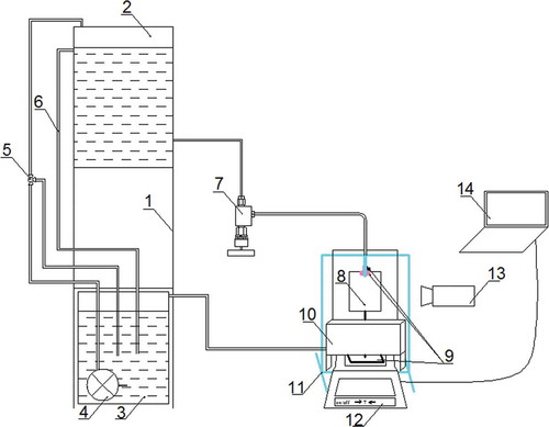
The wetting properties experiments of conventional carbon steel and modified carbon steel surfaces were carried out with an automatic measuring device, as presented in . Basically, it consists of water supply part, test part, and data acquisition part. The most important apparatus of data acquisition part is the precision electronic balance (XS204; Mettler Toldeo, Switzerland), and its weighing range is 0.0001~220.000 g with linearity error of 0.2 mg. A computer controlled the apparatus and collected the weight data simultaneously. The test was run in the following procedure at the atmospheric environment. The water supply part worked firstly, and the flow rate was steadily controlled through the needle valve. The circulation pump, the triple valve, and the overflow tube cooperated to maintain a steady height level of the water feed tank. Then the distilled water entered a liquid distributor fixed on the feed holder, which could move with the feed holder motion. The samples were hanged over the sample holder, which was placed on the pan of the electronic balance. The most important thing was to move the feed holder and make sure that the liquid distributor was very closer to the test sample but no contact. The stream fell down along the sample surface due to gravitation and distributed horizontally due to capillary action or other assisted by gravitation. At last, the water dripped down to the collection tank in which the water would be circulated. Meanwhile, a high-resolution camera (FDR-AX100E; Canon (China) Co., Ltd., Japan) was placed face to face with the test sample to record the stream flowing along the surface.
Figure 2. Schematic diagram of the mechanism experiments: 1, base support; 2, feed tank; 3, storage tank; 4, circulation pump; 5, triple valve; 6, overflow pump; 7, needle valve; 8, test sample; 9, sample holder; 10, collection tank; 11, feed holder; 12, electronic balance; 13, camera; 14, computer.
Pilot-scale test
As shown in , the test apparatus included high-voltage power supply system, water film distribution system, simulated flue gas system, induced draft fan, and wet ESPs shell. The discharged electrodes used barbed wires. The distance between two collectors was 400 mm, each collector was 500 × 500 mm2, and the total useful length was 4 m. The modified rigid collector was connected to the nylon fabric with insulation sheet and bolts; the water pipe was wrapped in the nylon fabric (patent no.: CN201320818783.5).
Figure 3. Schematic diagram of the test apparatus: 1, wet ESPs shell; 2, insulation; 3, DC power; 4, rotameter; 5, water distribution pipe; 6, collection electrode; 7, discharge electrode; 8, tank; 9, circulating water; 10, water pump; 11, aerosol generator; 12, particles feed port; 13, heater; 14, induced draft; 15, regulating valve; 16, export sampling port; 17, inlet sampling port.
The DC power supplied negative voltage in the range of 20~70 kV. The water film distribution system supplied uniform water film on the surface of the collection electrode, and the collected particles were scoured into the dust bucket and then the water containing the particles entered the tank to deposit. After that, the water pump pumped the supernatant circulating water to the water distribution pipe. The rotameter regulated the flow rate range of 16~60 L/hr. The solid aerosol generator (SAG-410; Topas GmbH, Germany) supplied a suitable amount of test particles from the particles feed port at a predetermined rate. The compressed air carried the suitable amount of particles entering into the inlet sampling port. The mass concentrations of particles were calibrated by dust meter (3012H; Laoshan Applied Technology Research Institute, China) meanwhile. The particles mixed with the hot gas heated by the heater and the flue gas was drawn into the wet ESPs shell by an induced draft. The test temperature range was 20~90 °C. The charged particles moved to the collection electrode and were arrested by the water film in the electric field. The residence time of particles in the wet ESPs shell was controlled by the regulating valve adjusting the flue gas velocity. The residence time was 1.6~4.0 sec, the range of the gas velocity was 1.0~2.5 m/sec. The electrical low-pressure impaction (ELPIVI 4.00; Dekati Ltd., Finland) was used to measure the variation of the number concentration at the inlet and export sampling ports. The test particles were obtained from the industrial smoke dust through the screening by electromagnetic high-frequency vibrating screen. The size distribution of the particles is shown in . The tempetature was measured by type K thermocouples with the test range of −40~99 °C and the measurement error of ±0.1 °C. The gas velocity was measured by hot-bulb anemometer (QDF-3; Beijing Testing Instrument Co., Ltd., China) with the test range of 0.05~30 m/sec and the measurement error of ±4%U.
Figure 4. Characteristics of number distribution of particles in experiments.
Definition of principal parameters
In many research papers, the film interface dynamics depend largely on the wettability of the test section surface and the surface tension of the working fluid (Zhou et al., Citation2009). In this experiment, the film interface dynamics depends mainly on the former reason in view of coating-specific composite. The definitions of principal parameters for wetting characteristics are listed in .
Table 2. Definition and description of the surface wetting characteristics parameters.
The mass concentration of particles entering the wet ESPs, Cin, and the mass concentration leaving the wet ESPs, Cout, were monitored by dust meter. Thus, the collection efficiency (η) could be derived as
The number concentration of particles entering the wet ESPs, Nin(di), and the number concentration leaving the wet ESPs, Nout(di), were monitored by ELPIVI 4.00. The collection efficiency of the particles with diameter of di (ηdi) could be derived as
where di is the aerodynamic diameter of the test particles.
Results and discussion
Characterization of the sample surfaces
The SEM images of the sample surfaces are shown in . The conventional carbon steel (CCS) surface emerges gill structure after polished, and the epoxy resin (ER) surface has a smooth surface. The modified carbon steel (MCR) surface has the upper layer glass fiber bundles possessing loose and unbounded.
Figure 5. The SEM images of the sample surfaces of (a) CCS; (b) ER; (c) modified carbon steel (ambient temperature).

The static contact angle was measured with the Kruss K12 Program interface tensiometer. Five microliters of distilled water was taken as the probe liquid, and the static contact angle was measured at least in five different positions, then the average value was taken as the final result. The precision of the measurement was ±2°. The test interface and contact angle of the surfaces are shown in . The conventional carbon steel surface has a static contact angle of 56°, and the epoxy resin and the modified carbon steel surfaces have the static contact angles of 61° and 0°, respectively. We have made the hypothesis that the conventional carbon steel surface coating single vinyl ester resin has no significant promotion in wettability; on the contrary, the results would be totally different in case we introduce capillary action. This hypothesis has been confirmed by using glass fiber bundles forming the upper loose and unbounded layer on conventional carbon steel surface, as shown in . It is important to note that the modified carbon steel surface has the static contact angle of 0°. According to this figure, a perfect wetting surface was obtained when the modified methods acted in accordance with our recommended techniques. However, these data seem not sufficient for modified carbon steel surface, and it is essential to discuss some important factors to interpret the transformation such as liquid holdup, surface flow rate, film rate, average film thickness, critical saturation time, and so forth.
Figure 6. Test interface and contact angle (CA): (a) CCS (CA: 56°). (b) ER (CA: 61°). (c) modified carbon steel (CA: 0°).
The wetting properties experiments
Liquid diffusion over the sample surfaces
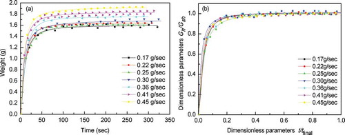
The influence of supply water flow rate on the liquid diffusion process characteristics of the S2 surfaces is exhibited in . As shown in , the liquid weight of the surfaces reached a high value within about 75 sec and the S2 surface can get wetted totally at all supply water flow rate. And then the weight value presented up and down around the high value. The liquid accumulated at the bottom edge of the test sample for a few seconds due to the liquid surface tension larger than the gravity that made the value up. And then the liquid dripped down due to the latter getting larger that made it down. The phenomenon repeated continuously. In the following calculation, the surface liquid weight used the average value of the stable period data. The weight of the water film over the surfaces is 1.5~1.9 g, and the corresponding saturated liquid holdup is 0.019~0.024 g/cm2. shows the dimensionless parameters. The supply water flow rate has no obvious different influence on the liquid diffusion process. The water film weight over the surface can reach critical saturation state in 20% final time. That means that we can use a smaller supply water flow rate to wet the surface in less than 1 min. So we choose the flow rate of 0.22 g/sec (flow rate per unit horizontal length, ql = 0.0275g/(sec·cm)) to discuss the influence of sample treatment temperatures.
Figure 7. The influence of supply water flow rate on the liquid diffusion process characteristics of the S2 surfaces: (a) the water film weight by time; (b) the dimensionless weight by dimensionless time.
Effects of sample treatment temperatures
The effects of sample treatment temperatures on the wetting properties of the conventional carbon steel and the modified carbon steel surfaces at flow rate of 0.22 g/sec are listed in . As shown in the table, the initial weight win refers to total weight of the holder and test sample placed on the electronic balance. When the film rate is 100%, the average film thickness has the same value with the saturated liquid holdup. The consistent surface flow rate at different temperatures is due to the 100% effective water film area and the same feed water flow rate. Here we make a hypothesis to get the parameter of the surface flow rate that all surfaces can get wetted totally in ideal state. That means per square meter area of the conventional carbon steel surface needs much larger flow rate to get wetted compared with the modified carbon steel surfaces. shows the liquid diffusion process characteristics on the surfaces at flow rate of 0.22 g/sec and the corresponding fitted curves of the samples. The critical saturation time is read out of the fitted curve through calculation with the data obtained and fitted. The relative error between the test and the fitted saturated liquid holdup is lower than ±5%.
Table 3. The wetting characteristics parameters of surfaces at flow rate of 0.22 g/sec (ql = 0.0275 g/(sec·cm)).
Figure 8. The sample treatment temperatures’ influence on the liquid diffusion process characteristics over the surfaces at flow rate of 0.22 g/sec. (a) The water film weight by time. (b) The dimensionless weight by dimensionless time.
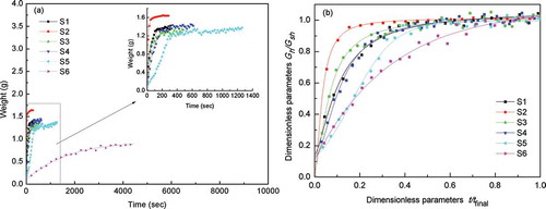
It can be seen that the water film weight of S2 surface presented an approximately vertical raise once the distilled water contacted the surface; in the end, the water film weight reached steady and saturated with a certain value. The water film weights of S1, S3, S4, and S5 surface rose slower than that of the S2 and reached steady and saturated with a certain value in different numbers of seconds. The critical saturation time of S1~5 surfaces is less than 500 sec, which is suitable in the industrial application, and the saturated liquid holdup is more than 0.0162 g/cm2, which is 8 times more than that of the conventional carbon steel surface. The water film weight of S6 surface increased very slowly, with the critical saturation time exceeding 3600 sec and the saturated liquid holdup is only 0.0110 g/cm2. Despite all this, the S6 surface has better wetting properties than the conventional carbon steel surface. The liquid diffusion process over S1~4 surfaces conform to Hill distribution respectively, the S5 surface conforms to dose-response distribution, and the S6 surface conforms to exponential distribution.
shows the dimensionless parameters about the weight by time. The water film weight could reach critical saturation state in less than 20% final time for the S2 surface. That is about 40% for the S1, S3, S4, and S5 surfaces and 70% for the S6 surface. The influence of sample treatment temperatures on the driving force for liquid spreading was significantly different. For the S2 surface, the capillary sorption may be the mainly driving force for liquid spreading. For S6 surface, the gravity force plays an important part during the preliminary stage of the liquid spreading. For the other surfaces, they both work for liquid spreading but with competition.
The pilot-scale test
shows the comparison of collection efficiency among the conventional rigid collectors, modified rigid collectors, and flexible collectors. The conventional rigid collectors used the common Z-type collectors; the flexible collectors used the polypropylene fibrous collectors. The particles inlet mass concentration was 100 mg/m3, the velocity of the flue gas was 1 m/sec, the treatment time that the particles stayed in the wet ESPs shell was 4 sec, and the temperature of the flue gas was 50 °C. The surfaces of the conventional rigid collectors were dry; the surfaces of flexible collectors and the modified rigid collectors had uniform water film with the circulating water flow rate of 20 L/hr. The applied voltage used in the conventional rigid collectors and the flexible collectors increased from 30 to 60 kV, whereas the applied voltage used in the modified rigid collectors increased from 30 to 44 kV because of some construction and installation problem. shows the effect of voltage on particles collection efficiency. It can be seen that the collection efficiency by the three collectors all increased when the applied voltage increased. Using the modified rigid collectors had higher collection efficiency than the conventional rigid collectors and flexible collectors when the applied voltage was lower than 44 kV. The collection efficiency using the modified rigid collectors at 44 kV was almost equal to that of using flexible collectors at 60 kV.
Figure 9. The effect of voltage on particles collection efficiency among CRC, MRC, and FC.
shows the particles distribution using modified rigid collector with dry and wet surfaces without applied voltage. It can be seen that the water film had higher collection efficiency for the particles with diameter ≤0.48 μm. The water film could catch the smaller particles by reducing the reentrainment. shows the comparison of the particles number concentration collection efficiency on each stage among the three collectors. It can be seen that the collection efficiency by conventional rigid collectors increased when the applied voltage increased from 40 to 60 kV. And the collection efficiency of the particles with diameter ≤1 μm increased more than those with diameter >1 μm. As the applied voltage rises up, the average electric field intensity increases inside the electrostatic precipitators and the space-charge density also increases at the same time, which promotes the collection of the submicron particles. The surface of flexible collectors could be covered with uniform water film. That made its collection efficiency higher than by the conventional rigid collectors, especially for the particles with diameter ≤1.23 μm at the applied voltage of 60 kV. However, the larger particles had almost equal collection efficiency. We could infer that as the applied voltage increased higher, the collection efficiency would not increase obviously. Using the modified rigid collectors at the applied voltage of 44 kV had almost equal collection efficiency compared with by the flexible collectors at the applied voltage of 60 kV. Particles with diameter ≤0.32 μm even had higher collection efficiency. The existence of uniform water film results in the lack of back corona and reentrainment of dust, and the higher discharge current and the flue gas humidity increase because of the water film evaporation improve the particles charge number and electrotransport speed, which all could increase the collection efficiency of the particles.
Figure 10. The particles distribution using modified rigid collector with dry and wet surfaces without applied voltage. (Inlet concentration: 100 mg/m3; SCA: 20 m2/(m3/sec); temperature: 50 °C.)
Figure 11. The number concentration collection efficiency on each stage among CRC, MRC, and FC. (Inlet concentration: 100 mg/m3; SCA: 20 m2/(m3/sec); temperature: 50 °C.)
shows a similar tendency of current-applied voltage curve for the three collectors. The current by modified rigid collectors was about 100% higher than the flexible collectors; and the current by flexible collectors was 70~100% higher than the conventional rigid collectors at same applied voltage. shows that the collection efficiency by the modified rigid collectors was higher than the flexible collectors and the conventional rigid collectors at same corona power. When the collection efficiency was 95%, the corona power by the modified rigid collectors (9.36 W) was smaller than the flexible collectors and the conventional rigid collectors (12.5 W). The results indicated that using the modified rigid collectors could decrease the energy consumption. As shown in , the specific collecting area increased from 8 to 20 m2/(m3/sec). The collection efficiency by conventional rigid collectors increased from 67% to 95% and the collection efficiency by flexible collectors increased from 85% to 97% with applied voltage of 60 kV. And the collection efficiency by modified rigid collectors increased from 74% to 97% with applied voltage of 44 kV. The specific collecting area increased, resulting in the increase in treatment time that the particles stayed in the wet ESPs shell, and more particles were collected.
Figure 12. The characteristics of current-applied voltage. (Inlet concentration: 100 mg/m3; SCA: 20m2/(m3/sec); temperature: 50 °C.)
Figure 13. The relationship between collection efficiency and corona power. (Inlet concentration: 100 mg/m3; SCA: 20 m2/(m3/sec); temperature: 50 °C.)
Figure 14. The effect of SCA on particles collection efficiency among CRC, MRC, and FC. (Inlet concentration: 100 mg/m3; temperature: 50 °C.)
Using the modified rigid collectors could decrease the energy consumption and had better collection effect, especially for the ultrafine particles efficiency with guarantee of high collection efficiency. The circulating water consumption in the application of the modified rigid collectors was 0.04 t/(hr·m2), which was far less than the stainless steel collector of 0.3 t/(hr·m2) (Wang, Citation2013). In conclusion, the modified rigid collector has potential for application with lower energy and water consumption.
Conclusions
Modification of conventional carbon collector surfaces by coating vinyl ester resin composite was studied. The rigid collector surfaces before and after modification had been characterized by SEM and interface tensiometer. The effect of operating temperatures on the wetting properties of the rigid collector surfaces before and after modification was investigated.
The sample surface with treatment temperature 50 °C reveals remarkable wetting properties. The saturated liquid holdup of this surface is about 10 times more than that of the conventional carbon steel surface. The film rate of this surface is almost 30 times more than that of the conventional carbon steel surface. The average film thickness is about 36~46% of the value of the conventional carbon steel surface. The surface flow rate was reduced more than 94% compared with the conventional carbon steel. The remarkable wetting properties benefited from the capillary channels provided by the glass fiber cloth with loose glass fiber bundles. Both the capillary sorption and the gravity force work for liquid spreading but with competition for the samples at other temperatures. The modified surfaces can keep admirable wetting properties in the wet ESPs environment.
The wet ESPs by the modified rigid collectors exhibited significantly higher particles collection efficiency than by conventional rigid collectors. The uniform water film over the modified rigid collectors surface makes the collection efficiency for ultrafine particles (≤0.32 μm) higher. The circulating water consumption over per square meter the modified rigid collectors’ surface decreased 86% than the stainless steel collector in the application. The modified rigid collector has potential for application with lower energy and water consumption.
Funding
This work was financially supported by the National Natural Science Foundation of China (51206097, 51006063), the Shandong Province Natural Science Foundation, China (ZR2011EEQ019, 2014EEM040, 2014ZZCX05201), and the Fundamental Research Funds of Shandong University (2014QY001-04).
Additional information
Funding
Notes on contributors
Chunyan Xu
Chunyan Xu is a doctoral degree candidate, Jingcai Chang has received a doctoral degree, Zhen Meng has received a master’s degree, Xiang Wang is a doctoral degree candidate, Jing Zhang is a master’s degree candidate, Lin Cui is an associate professor, and Chunyuan Ma is a professor at the School of Energy and Power Engineering, Shandong University, China.
Jingcai Chang
Chunyan Xu is a doctoral degree candidate, Jingcai Chang has received a doctoral degree, Zhen Meng has received a master’s degree, Xiang Wang is a doctoral degree candidate, Jing Zhang is a master’s degree candidate, Lin Cui is an associate professor, and Chunyuan Ma is a professor at the School of Energy and Power Engineering, Shandong University, China.
Zhen Meng
Chunyan Xu is a doctoral degree candidate, Jingcai Chang has received a doctoral degree, Zhen Meng has received a master’s degree, Xiang Wang is a doctoral degree candidate, Jing Zhang is a master’s degree candidate, Lin Cui is an associate professor, and Chunyuan Ma is a professor at the School of Energy and Power Engineering, Shandong University, China.
Xiang Wang
Chunyan Xu is a doctoral degree candidate, Jingcai Chang has received a doctoral degree, Zhen Meng has received a master’s degree, Xiang Wang is a doctoral degree candidate, Jing Zhang is a master’s degree candidate, Lin Cui is an associate professor, and Chunyuan Ma is a professor at the School of Energy and Power Engineering, Shandong University, China.
Jing Zhang
Chunyan Xu is a doctoral degree candidate, Jingcai Chang has received a doctoral degree, Zhen Meng has received a master’s degree, Xiang Wang is a doctoral degree candidate, Jing Zhang is a master’s degree candidate, Lin Cui is an associate professor, and Chunyuan Ma is a professor at the School of Energy and Power Engineering, Shandong University, China.
Lin Cui
Chunyan Xu is a doctoral degree candidate, Jingcai Chang has received a doctoral degree, Zhen Meng has received a master’s degree, Xiang Wang is a doctoral degree candidate, Jing Zhang is a master’s degree candidate, Lin Cui is an associate professor, and Chunyuan Ma is a professor at the School of Energy and Power Engineering, Shandong University, China.
Chunyuan Ma
Chunyan Xu is a doctoral degree candidate, Jingcai Chang has received a doctoral degree, Zhen Meng has received a master’s degree, Xiang Wang is a doctoral degree candidate, Jing Zhang is a master’s degree candidate, Lin Cui is an associate professor, and Chunyuan Ma is a professor at the School of Energy and Power Engineering, Shandong University, China.
References
- Anderlohr, C., L. Brachert, J. Mertens, and K. Schaber. 2015. Collection and generation of sulfuric acid aerosols in a wet electrostatic precipitator. Aerosol Sci. Technol. 49:144–151. doi:10.1080/02786826.2015.1008624
- Bayless, D.J., M. Khairul Alam, R. Radcliff, and J. Caine. 2004. Membrane-based wet electrostatic precipitation. Fuel Process. Technol. 85:781–798. doi:10.1016/j.fuproc.2003.11.025
- Bayless, D.J., H. Pasic, and M.K. Alam. 2001. Use of membrane collectors in electrostatic precipitators. J. Air Waste Manage. Assoc. 51:1401–1407. doi:10.1080/10473289.2001.10464372
- Bayless, D.J., L. Shi, G. Kremer, B.J. Stuart, J. Reynolds, and J. Caine. 2005. Membrane-based wet electrostatic precipitation. J. Air Waste Manage. Assoc. 55:784–791. doi:10.1080/10473289.2005.10464658
- Castro, M.S. de, and O.M.H. Rodriguez. 2015. Interfacial waves in stratified viscous oil–water flow. Exp. Thermal Fluid Sci. 62:85–98. doi:10.1016/j.expthermflusci.2014.12.003
- Chang, J.C., Y. Dong, Z.Q. Wang, P. Wang, P. Chen, and C.Y. Ma. 2011. Removal of sulfuric acid aerosol in a wet electrostatic precipitator with single terylene or polypropylene collection electrodes. J. Aerosol Sci. 42:544–554. doi:10.1016/j.jaerosci.2011.05.006
- Chang, J.C., Y. Dong, J. Yan, B. Li, and C.Y. Ma. 2010. Performance test of a new wet ESP with flexible collection electrodes. In 4th International Conference on Bioinformatics and Biomedical Engineering.
- Córdoba, P., C. Ayora, N. Moreno, O. Font, M. Izquierdo, and X. Querol. 2013. Influence of an aluminium additive in aqueous and solid speciation of elements in flue gas desulphurisation (FGD) system. Energy 50:438–444. doi:10.1016/j.energy.2012.11.020
- Fujishima, H., and Y. Tsuchiya. 1993. Application of wet type electrostatic precipitators for utilities’ coal-fired boiler. In Joint Conference of Tenth Particle Control Symposium and Fifth International Conference on Electrostatic Precipitation, Washington, DC.
- Gao, J.G., C. Huang, and X.D. Qi. 2007. Membrane electrostatic precipitator—A new technique of electrostatic precipitation. Jiangsu Environ. Sci. Technol. 20:64–67.
- Jiang, H.T., S.G. Tian, Y.L. Fu, M.H. Jia, and Y.B. Zhang. 2014. Application of wet electrostatic precipitator in coal-fired power plants. Power Equip. 28:61–64.
- Kim, J.H., H.J. Yoo, Y.S. Hwang, and H.G. Kim. 2012. Removal of particulate matter in a tubular wet electrostatic precipitator using a water collection electrode. Sci. World J. Article ID 532354. doi:10.1100/2012/532354
- La, D. 2007. The Perpendicular Wall That Takes Patulous Side Falls Film Evaporates Mechanism Research. Shanghai, China: Tongji University.
- Lu, C., R.Q. Duan, and S.Y. Jiang. 2008. Experimental study of flow instabilities of falling films. Tsinghua Univ. (Sci. Technol.) 48:1487–1489.
- Luo, D.Q., Y.C. Li, Y. Fang, and G.C. Dai. 2011. Wettability of modified polymer surface and liquid film behavior. J. East China Univ. Sci. Technol. (Nat. Sci. Ed.) 37:274–280.
- Mertens, J., C. Anderlohr, P. Rogiers, L. Brachert, P. Khakharia, E. Goetheer, and K. Schaber. 2014. A wet electrostatic precipitator (WESP) as countermeasure to mist formation in amine based carbon capture. Int. J. Greenhouse Gas Control 31:175–181. doi:10.1016/j.ijggc.2014.10.012
- Miyara, A. 2000. Nmerical simulation of wavy liquid film flowing down on vertical wall and an inclined wall. Int. J. Thermal Sci. 39:1015–1027. doi:10.1016/S1290-0729(00)01192-3
- Moran, K., J. Inumaru, and M. Kawaji. 2002. Instantaneous hydrodynamics of a laminar wavy liquid film. Int. J. Multiphase Flow 28:731–755. doi:10.1016/S0301-9322(02)00006-X
- Peukert, W., and C. Wadenpohl. 2001. Industrial separation of fine particles with difficult dust properties. Powder Technol. 118:136–148. doi:10.1016/S0032-5910(01)00304-7
- Shen, L.Y. 2006. The Computation of Material Balance for an Advanced Ammonia Desulphurization Technology and the Performance Optimization of the Mist Separator. Beijing, China: North China Electric Power University.
- Takamasa, T., and T. Hazuku. 2000. Measuring interfacial waves on film flowing down a vertical plate wall in the entry region using laser focus displacement meters. Int. J. Heat Mass Transfer 43:2807–2819. doi:10.1016/S0017-9310(99)00335-X
- Ueda, Y., K. Tomimatsu, M. Kagami, and H. Fujishima. 2001. Development of advanced gas cleaning system for sub-micron particle removal. In Eighth International Conference on Electrostatic Precipitation, Birmingham, Alabama.
- Wang, R.F. 2007. Falling Film Flow Characteristics on Vertical Plate. Dalian, China: Dalian University of Technology.
- Wang, X.H. 2013. Enhancement Mechanism and Process of Water on Particle Removal in Electrostatic Filed. Beijing, China: Tsinghua University.
- Xue, M.J., and N.S. Zong. 1997. Characteristics of the wet electrostatic precipitator and a direction of development. Electric Power Environ. Prot. 13:40–44.
- Zhang, A.P. 2009. The application of coal-fired boiler flue gas ammonia desulphurization technology. Environ. Sci. Survey 28:58–61.
- Zhao, L., and R.L. Cerro. 1992. Experimental characterization of viscous film flows over complex surfaces. Int. J. Multiphase Flow 18:495–516. doi:10.1016/0301-9322(92)90048-L
- Zhao, X.G., W. Li, Z.B. Zhang, and Y.H. Xu. 2011. Suppression of liquid film rupture during falling film evaporation for high salinity wastewater. Chin. J. Environ. Eng. 5:726–730.
- Zheng, Y.J., and Y.F. Hu. 2009. The analysis and research of the performance factors in the wet electrostatic precipitators. Sci. Technol. Inform. 24:234.
- Zhou, D.W., T. Gambaryan-Roisman, and P. Stephan. 2009. Measurement of water falling film thickness to flat plate using confocal chromatic sensoring technique. Exp. Thermal Fluid Sci. 33:273–283. doi:10.1016/j.expthermflusci.2008.09.003