
 ?Mathematical formulae have been encoded as MathML and are displayed in this HTML version using MathJax in order to improve their display. Uncheck the box to turn MathJax off. This feature requires Javascript. Click on a formula to zoom.
ABSTRACT
Collecting plate is the core component of the electrostatic precipitator. In order to explore the influences of the plates shape and electrode configuration on the particle precipitation process, numerical models of an ESP with seven different types of collecting plates were established and calculated. The simulation results showed that the shape of the collecting plate did have a great impact on the electric field, airflow particles movement. From the perspective of electric field characteristics, the space current density and electrostatic shielding effect in multielectrode ESPs varied with the shape of the plates under the same supply voltage. When using C-type plate, the shielding effect was minimal and the current density distribution of the plate was more uniform. When it comes to airflow distribution, small vortex structures were easily generated near the plates when the CW type, the rod-curtain and Z-type plates were used, leading to particle re-entrainments. In terms of collection efficiency, the C-type plate enjoyed the highest efficiency, while the ZT-type and corrugated plate were less efficient.
Implications: The main source of air pollution is the flue gas released by fuel combustion. electrostatic precipitator plays an important role in pollutant discharge control and environmental protection. As the core component of the electrostatic precipitator, the form of the collecting plate exerts a serious impact on its dust removal performance. The study focuses on the analysis of the collecting plate shape on the electric field characteristics of electrostatic precipitators, flow distribution characteristics and the influence of the collecting efficiency. It is expected that through the research, some guidance will be provided with the electrode configuration selection and optimization of ESP.
Introduction
In the recent report of the landmark “Global Environment Outlook”, the United Nations stated that harsh environmental conditions had caused about 25% of diseases and deaths worldwide (Banuri, Prates, and Martino Citation2019). Air pollution causes frequent diseases such as lung cancer, resulting in 6 to 7 million premature deaths each year. The main source of air pollution is the flue gas released by fuel combustion. At present, thermal power generation occupies a large market share in the world, producing a large number of particulate pollutants. As a pollutant emission control and environmental protection device for thermal power plants, electrostatic precipitators play an important role in environmental protecting (Sun, Cheng, and Lang Citation2018; Xue, Tian, and Yan Citation2016). However, due to the gradual strictness of pollutant emission standards, higher requirements have been placed on the performance of electrostatic precipitators. Establishing a clean, low-carbon, safe and efficient ESP system is imminent. As the core component of the electrostatic precipitator, the form of the collecting plate exerts a serious impact on its dust removal performance.
Most of the current research are aimed at the exploration of electrode configuration, but the focus of which is only limited to the form and arrangement of the discharge electrodes, the wire-to-wire spacing, and the wire-to-plate spacing. For example, Zhiyuan Ning studied the effect of the arrangement of the discharge electrodes on the airflow mode and ESP collection efficiency (Ning, Podlinski, and Shen Citation2016). Xi Xu compared the effects of three different structures of discharge electrode on high temperature electrostatic precipitators through experiments. The results show that the rod electrode is more suitable for high temperature electrostatic precipitators (Xu, Zheng, and Yan Citation2016). Park and Kim (Citation2000, Citation2003) studied the flow characteristics of a simple geometric model ESP consisting of a single line with a cavity through experiments and numerical calculations. Compared with experimental methods, numerical simulation is preferred because of its flexibility, low cost, and relatively high accuracy (Shen et al. Citation2018). Therefore, several numerical models have been established to study corona discharge and particle removal processes in ESP (Long and Yao Citation2010). For example, (Anagnostopoulos and Bergeles Citation2012) proposed an improved numerical model for calculating the electric field induced by corona discharge in a wire-plate electrostatic precipitator. The finite difference method (FDM) is used to solve the potential equation in an orthogonal curvilinear coordinate system. However, as a major component of ESP, collection plates were often idealized as flat-plate structures, which was unreasonable (Adamiak and Atten Citation2009; Farnoosh, Adamiak, and Castle Citation2010; Lu, Yang, and Zheng Citation2016). In spite of that, some scholars having also been aware of the importance of the shape of the plates. Dang Xiaoqing et al. reported that the 480 C type collecting plate was wildly used in modern industrial ESPs due to the advantages of lighter weight and less cost (Xiaoqing, Wei, and Xuelian Citation2006). Lami, Mattachini, and Gallimberti (Citation1995) numerically studied the electrical characteristics of C-type collecting electrodes by using the finite difference method. Neimarlija et al. take the advantage of Finite Volume Method to study the characteristics of electric field and flow field in C-plate type ESP (Neimarlija, Demirdžić, and Muzaferija Citation2011). Compared with the current density distribution on the C-plate type and the H-plate type, Wu Changfu found that the average current density of the C-plate was greater than that of the H-plate (Changfu and Yongan Citation1996). Fujishima, Ueda, and Tomimatsu (Citation2004) simulated EHD flow in typical industrial ESP geometry structure, i.e. spike discharge electrode and convex-concave collector plate. The results show that the collector concave area is favorable for particle capture.
However, most researches only focus on one type of collecting plate, and rarely consider the influence of different shapes of collecting plate in the electrostatic precipitating process. With the continuous development of new ESP types and electrode configurations, the electrode structure has become more and more complicated to improve ultrafine particles (such as PM 2.5). Therefore, it is very meaningful to systematically study the effects of complex electrode configurations on corona discharge, particle charging, and particle migration.
Based on the issues discussed above, our research group use COMSOL/Multiphysics tool to compare the performance of seven different shape of collecting plates, including ZT type, corrugated-plate type, CW type, Z type, Rod-curtain type, flat-plate type, C type. The influence of the shape of collecting plates on the electric field characteristics, airflow distribution characteristics and collection efficiency of ESP is analyzed. Firstly, the FEM method is used to solve the space charge density distribution and the current density distribution under the different collecting plates. Secondly, the k-w turbulence model is used to describe the distribution characteristics of the airflow. It is found that the ionic wind effect varies from different dust collecting plates. In other words, the coupling results of the main flow and EHD flow are quite different. Finally, the particle motion is described by the Lagrangian method, and the influence of the shape of collecting plates on collection efficiency is computed. It is expected that through the above research, some guidance will be provided for the electrode configuration selection and optimization of ESP.
Electrostatic precipitator mathematical model
Mathematical model of corona discharge
When the discharge electrodes (wires) are connected to a certain high voltage, an ionization region is formed near the wires due to corona discharge, and the air is ionized into both positive ions and negative ions. Positive ions move toward the wires, while negative ions move toward the collecting plates. At this time, the remaining area in ESP is called drift zone. Negative ions collide with dust particles passing through the area to charge them. The general equation for corona discharge in electrostatic precipitator is as follows (White Citation1963):
Poisson equation:
The corona current density is defined as:
Relationship between potential and electric field:
In general, the diffusion term in the current density equation is much smaller than the conduction term, which can be probably ignored (Kasdi Citation2016).
It can be seen from the above general equation of corona discharge that there is a strong correlation between the space charge density and the electric field strength. Therefore, the process of numerical calculation is essentially iterative. The Equationequations (1)(1)
(1) – (Equation4
(4)
(4) ) are collated to obtain the relationship between the charge density and the electric field strength, as shown below.
The boundary condition of ESP potential defined as discharges are extremely high negative voltage and collecting plates are zero. The Kaptzov’s hypothesis is used to set the electric field strength on the discharge electrode. It puts forward that the field strength on the surface of the wires remains constant after corona discharge. The threshold field strength is calculated by the Peek’s formula (Theodore Citation2008):
With the Finite Element Method (FEM) to solve the above equations, the discharge characteristic can be computed accurately.
The difficulty in solving the electric field in ESP lies in the calculation of the space charge density. Usually the solution method is: make estimation of the initial charge density value on the surface of the discharge electrodes, the value is then iterated continuously until the electric field strength of the wire surface is equal to the threshold field value. Now, a fully coupled method can be used to solve the Poisson equation and the current continuous equation to obtain the potential and charge density distribution. Firstly, simply split space charge density
into two parts, the first one is constant
and the other one is space-dependent
. Substituting the above formula into Equationequation (5)
(5)
(5) (6) we can obtain the relationship between space dependent variable dρ and electric field strength E:
Define boundary condition () on the surface of the discharge electrode subject to the Katpzov’s hypothesis. In order to obtain the
on the surface of the discharge electrode, an arbitrary point (P) is selected on the wires, as a Lagrange multiplier
. The boundary condition on the P point can be applied by COMSOL/Multiphysics,0 =
-
. Since
is only defined in point P, it is be generalized to become a global quantity
,which is available anywhere in the subdomain. Through the coupling integral of
,
can be obtained.
Mathematical model of airflow
When the ESP is working, the airflow contains a large amount of dust particles enters the electrostatic precipitator. Since gas ions are affected by electric field force, the flow pattern of the airflow is also disturbed by the electric field through the way of ionic wind. In order to study the airflow pattern, the Reynolds averaged equations of mass continuity and momentum conservation (He and Dass Citation2018) are usually used to solve the unique properties of the airflow velocity and pressure
.
Where ρ(-∇φ) is the body force, which is the direct embodiment of the electric field acting on the air flow. This section uses a turbulence model to simulate the flow of airflow within the ESP and uses the k − equation (Butler, Cendes, and Hoburg Citation1989) to solve the turbulent flow energy k and the specific dissipation rate ω (the dissipation of flow energy per unit), Its general equation is as follows:
Where:
The parameter values are as follows (COMSOL, 4.3 b Citation2013).
Particle charge and motion model
It is assumed that the dust particles are spherical and electrically neutral. There are two kinds of charge mechanism in the space: field charge and diffusion charge. The former is the ions generated by corona discharge accelerated by the electric field to collide with the particles to electrify them. The latter is the diffusion of ions due to thermal motion. When the particle charge is less than the saturated charge
, it is mainly driven by the field charge. On the contrary, the diffusion charge dominates. The saturation charge of a particle anywhere in space is calculated as follows:
In this paper, the Lawless (1996) model (Lawless Citation1996)is used to describe particle charge. The charge rate of particles in this model is the combination of field charge rate and diffusion charge rate. Its calculation formula is as follows:
Among the above equations, some variables can be calculated as the following equations:
Particles in ESP are considered to be discrete phases, and the study of particle transport is greatly concerned with the motion characteristics of single particles. Therefore, the Lagrangian model is used to describe particle motion (Jianping, Yuying, and Yongxia Citation2011). In addition to the electric field force, the charged particles are also subjected to the drag force and gravity, which realize the movement of particles to the collecting plates. According to Newton’s second law, its motion equation can be written as follows.
In the above equation, the can be calculated by the following equation.
Computation details
Geometry of the modeled ESP
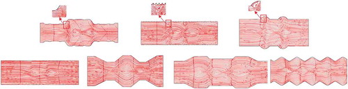
Above all, seven shapes of wire-plate electrostatic precipitators are built. 1/2 ESP models are shown in :
Figure 1. Schematic diagram of seven kinds of dust collecting plates.
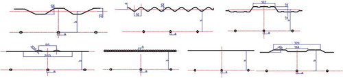
Arranging three discharge electrodes at the same intervals in the middle of two collecting plates. Additionally, ensure that the wire-to-plate spacing in the seven models are equal. The main physical parameters are selected as shown in
Table 1. Electrostatic precipitator parameters and operating parameters.
Grids and boundary conditions
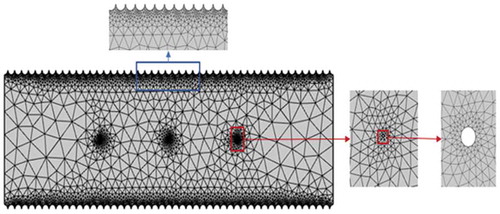
In order to mesh the 2D computational domain, a free triangle mesh element is used in the region. A fine mesh is implemented around the discharge electrode and the collecting plates to improve the modeling accuracy. The division of the computational domain grid of ESP with Rod-curtain type plate is shown in the .
Figure 2. Computational mesh of the Rod-curtain type electrostatic precipitator.
There are the following boundary conditions in the ESP channel, as shown in . The discharge electrodes are connected with negative high voltage, the dust collecting plates are grounded, and there is zero flux at the inlet and the outlet. At the same time, the initial velocity of the gas flow and the particles are set at the inlet. The outlet is set as the pressure outlet, and the boundary condition of the wall without slip is adopted.
Table 2. Boundary conditions in electrostatic precipitator.
Implement method
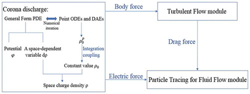
The turbulent flow field was solved by the k-w turbulence model model and standard wall functions. The particle motion trajectory is calculated by the Lagrangian approach. And using Lawless model to formulate the particles charging rate. Numerical analysis of the above equations in COMSOL/Multiphysics. Firstly, the general equations of corona discharge are solved by General Form PDEs and Point ODEs and DAEs until the equation converges. Thus, solving the space charge density and electric field distribution. Defining the flow in the Turbulent Flow module is an incompressible flow, and the body force solved in the electric field is applied to the turbulence model. Finally, the charging and motion of the particles are realized in the Particle Tracking for Fluid Flow module. The motion of the particles is closely related to the electric field force and drag force solved above. The specific process and links are as follows :
Figure 3. Implementation method and connection between physical modules.
Numerical simulation and results analysis
In this section, the performance of seven kinds of collecting plates are compared from the aspects of electric field characteristics, air flow and collection efficiency. It reveals the multi-physics coupling law of ESP.
Modal validation
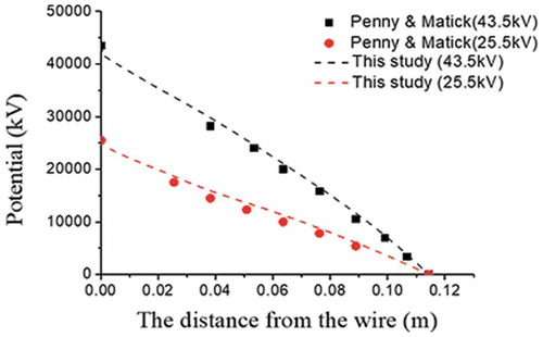
In order to verify the accuracy of the method of this study, the numerical simulation results are compared with other experimental or numerical results. shows the change of potential from the discharge electrode to the collecting plate at 43.5kV and 25.5kV. The dotted lines show the numerical simulation results computed by this model. The discrete points are the result of the experiment measured by Penny & Matick (Penney and Matick Citation1960).
Figure 4. Comparison of potential computed with present model and experimental results by Penny & Matick.
In addition, comparing the flow streamlines under different voltages. The EHD flow distribution in the channel is obtained under 40 and 50 kV in this study, as shown in , b). Correspondingly, the PIV test results in the Zhiyuan Ning’s study are shown in , d) (Ning, Podlinski, and Shen Citation2016). In both cases, the results in this paper are consistent with those in the literature.
Figure 5. Comparison of flow streamlines computed in this paper.
Finally, in order to verify the efficiency of dust removal, the same experimental model as (Kihm, Mitchner, and Self Citation1987) was established. The numerical simulation results are compared with Kihm’s experimental results, as shown in .
Figure 6. Comparison of dust removal efficiency.
Analysis of electric field characteristics
In this section, a corona voltage of −18 kV is applied to three discharge electrodes. The Poisson equation and the current continuity equation are solved by using the Finite Element Method. The electric field characteristics of ESP with seven kinds of collecting plates are discussed. (a–c) illustrate the magnitude of the electric field strength when Y = b/4, b/3 and 2b/3, respectively. (Define Y = 0 on the centerline of the ESP channel)
Figure 7. Magnitude of electric field strength (V / m) when using different shapes of collecting plates.
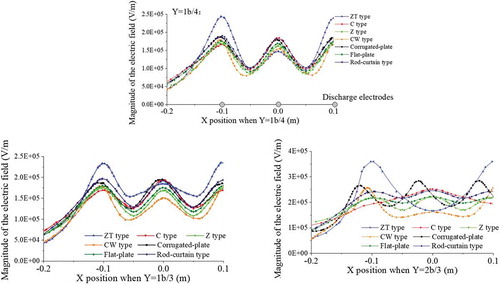
As can be seen from , at Y = 1b/4, the electric field strength near the discharge electrodes is hardly affectedby the shape of the collecting plates. And the electric field distribution under the other six collecting plates is almost the same except for the ZT-type plate. When the ZT-type collecting plate is used, the electric field strength near the both sides of electrodes are large, and the electric field strength in the middle portion is small. When Y = b/3, the distribution of electric field strength gradually becomes difference. When Y = 2b/3, the difference is very obvious. At this time, the distribution of the electric field strength is seriously affected by the shape of collecting plates. When the collecting plate of C type, Z type, Flat-plate type, and Rod-curtain type are used, the electric field distribution is relatively uniform. As for the corrugated plate, ZT type plate, or CW type, the electric field strength shows the obvious fluctuations.
In addition, from the aspect of uniformity of plate current density: C type> CW type> flat-plate type> Z type> corrugated-plate type > rod-curtain type > ZT type. The charge density distribution is evenly distributed on the C type, CW type and flat-plate type plates, but unevenly distributed on the ZT type plate.
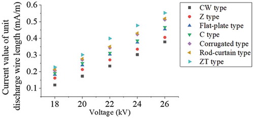
Simultaneously, the V–I characteristic fewer than seven different dust collecting plates are computed, as shown in . It is found that under the same voltage, the corona current value on the discharge wire per unit length: ZT type >rod-curtain type> corrugated-plate type >C type > flat-plate type >Z type > CW type. Moreover, the spacing of the two plates at the both sides of the ZT plate is small, resulting in a large current density on the surface of the discharge electrodes.
Figure 8. Effect of the shape of collecting plate on V–I characteristics.
Analysis of suppress effect under different plates
In the charge density analysis under seven working conditions, it is found that the discharge electrodes on both sides suppressed the corona discharge of the intermediate wire, that is, the Electrostatic Shielding Effect. And the effect varies with the shapes of the dust collecting plates. The charge density distribution on the dust collecting plate is calculated, as shown in . The shows the space charge density distribution under the C, Rod-curtain and ZT type collecting plates.
Figure 9. Charge density distribution curve of plate.
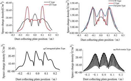
Figure 10. Space charge density(C/m3) distribution cloud map.
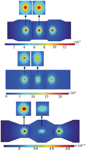
Comparing the above cloud diagrams, it can be seen that under the same conditions, the space charge density near the intermediate discharge electrode is different, which is caused by different degrees of shielding effects. When the dust collecting plate is C type, the space charge density around the left discharge electrode and the intermediate discharge electrode is almost the same. The intermediate discharge electrode is hardly affected by the electrodes on both sides. As for the Rod-curtain plate, the space charge density generated by the intermediate discharge electrode is obviously weaker than that of the electrodes on both sides, and the electrostatic shielding effect is strong at this time. In order to further explore the shielding effect under different collecting plates, the difference in space charge density between the inner and outer discharge electrodes is extracted, as shown in the . In addition, by analyzing the ESP streamline distribution at v = 0 m/s and v = 1 m/s, the airflow velocity has a great influence on the ion wind. This is because the greater the airflow velocity, the greater the cohesion between fluids, and the less susceptible it is to current interference.
Figure 11. Comparison of space charge density on the surface of three discharge electrodes.
It can be concluded that different degrees of shielding effect are produced under the seven different collecting plates. The three types of collecting plates with the highest degree of shielding effect are: ZT Type, Rod-curtain Type, Z Type. Minimal shielding effect occurs when using C-type plate. The suppressed discharge electrode does not exert its maximum effect, thus resulting in waste of resources.
Airflow distribution characteristics under different plates
In addition to the influence of the shape of the dust collecting plate on the electric field distribution, this paper further explores its influence on the electrohydrodynamic (EHD) airflow distribution. Ionic wind is the product of corona discharge, which disturbs the uniformity of the airflow distribution and makes the streamline distribution very complicated. The difference in the shape of collecting plate leads to different electric field characteristics in the space, which has direct effect on the intensity and effect of the ionic wind. First of all, the airflow distribution characteristics in the ESP without the main flow are specifically extracted. As shown in . From the above analysis, the form of ionic wind is very similar. Four fully developed vortex structures are created around each discharge electrode, with large vortices at the upstream and downstream. However, the shape and size of the vortex are significantly affected by the structure of the collecting plates.
Figure 12. ESP streamline distribution (v = 0 m/s).
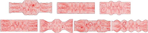
When the airflow passes, the distribution of airflow is the result of the coupling of the main flow and the EHD flow. When the initial velocity of the airflow is 1.0 m/s, the shows the streamline distribution in the channel.
Figure 13. ESP streamline distribution (v = 1.0 m/s).
When the velocity of airflow reaches 1.0 m/s, the main flow dominates, resulting in the vortex structure almost disappearing and the airflow distribution is relatively uniform. When using flat-plate type, ZT type, C type, corrugated-plate type collecting plates, the streamline is wavy and there is no vortex in the space. But when using CW type, rod-curtain type, Z type, there are still small vortex in the vicinity of the dust collecting plate, which is very likely to take away the dust that has already precipitated on the collecting plates, causing particle re-entrainment. In the industry, this phenomenon should be avoided as much as possible.
Collection efficiency analysis under different plates
Collection efficiency is a key indicator to measure the performance of ESP. It is the result of multi-physics coupling of electric field, airflow and particle transportation. This section assumes that the dust particles are spherical and electrically neutral, ignoring turbulent dispersion. So, the collection efficiency of particles with diameters of 0.5m, 1
m and 2.5
m is discussed when the corona voltage is −38 kV and the airflow velocity is 1.0 m/s.
It can be seen intuitively from that the highest collection efficiency can be obtained when the C type collecting plate is used, but the efficiency is the lowest when the corrugated-plate type and the ZT type are used. When the dust particle diameter is 2.5 μm, the collection efficiency of the C type collecting plates can be as high as 96%. At this time, the efficiency of the ZT type collecting plate is only 63%. When the particle diameter is reduced from 2.5 μm to 0.5 μm, the overall collection efficiency is lowered, but the magnitude of the decline is different. However, the highest collection efficiency is still obtained under the C dust collecting plate. It can be concluded that the collection plates of ESP are preferably of the C type.
Figure 14. Relationship between the shape of collecting plates and the collection efficiency.
Conclusions
In this paper, the ESP performance of seven different dust collecting plates is compared from the aspects of electric field characteristics, airflow distribution uniformity and collection efficiency, and the following conclusions are drawn:
The space charge density distribution and the electric field distribution are both highly correlated with the shape of the dust collecting plate. The electrostatic shielding is the least influential when using the C dust collecting plate and the ZT is the largest. At the same time, the current density uniformity under the C dust collecting plate is the best.
When there is no main flow, the forms of ionic wind under the seven kinds of dust collecting plates are almost the same, and the vortex structure in the channel is obvious. As the airflow velocity increases, the vortex structure gradually disappears. However, when CW type, rod-curtain type, Z type are used, small vortex structure is easily generated in the vicinity of the dust collecting plate, causing particle re-entrainment.
Under the C type dust collecting plate, highest collection efficiency can be obtained. When ZT type and corrugated-plate type plates are used, the dust collection efficiency is low.
Under different conditions, optimizing the structure of the dust collecting plate is of great significance to improve the performance of the electrostatic precipitator. We can achieve this through modeling and simulation. The mathematical model proposed in this paper provides an effective method to solve this problem. But it needs to be further developed, taking into account all key variables related to different geometries, such as operating conditions and material properties.
Nomenclature
| φ: | = | Potential |
| E: | = | Electric field strength |
| J: | = | Current density |
| ρ: | = | Space charge density |
| ε0: | = | Air relative permittivity |
| μ: | = | Ion mobility |
| D: | = | Diffusion coefficient |
| E0: | = | Threshold field strength |
| rc: | = | Radius of discharge electrodes |
| ρf: | = | Flow density |
| μ’: | = | Viscosity coefficient |
| εr: | = | Relative permittivityof the particle |
| dpar: | = | Particle diameter |
| α: | = | Continuous constants |
| w: | = | Continuous constants |
| e: | = | Electron charge |
| KB: | = | Boltzmann constant |
| T: | = | Temperature |
| mpar: | = | Mass of the particles |
| Z: | = | Number of charges |
| upar: | = | Velocity of the particles |
| uf: | = | Velocity of the airflow |
| ρpar: | = | Density of the particles |
| μ”: | = | dynamic viscosity of airflow |
Acknowledgment
The authors thank the China Section of the Air & Waste Management Association for the generous scholarship they received to cover the cost of page charges, and make the publication of this paper possible.
Disclosure statement
No potential conflict of interest was reported by the authors.
Additional information
Funding
Notes on contributors
Bing Chen
Bing Chen received Ph.D. degree in Beijing Institute of Tec-hnology (BIT) in 2005, China, Beijing. Now he works in Un-iversity of Science and Techn-ology Beijing (USTB). His cur-rent research interests include Air pollutant control, electrostatic precipitation technology.
Yongheng Guo
Yongheng Guo 2018.09–present, University of Science and Technology Beijing (USTB) majoring in mechanical engineering, studying for a master's degree. He obtained the first-class scholarship for graduate students and the title of excellent graduate student at University of Science and Technology Beijing (USTB). He published an SCI paper, an EI paper, and a Chinese core paper, and obtained two software copyrights.
Hongjiao Li
Hongjiao Li 2017.09–2020.1 Major in Mechanical Engineering, University of Science and Technology Beijing, Master Degree. She has won first-class scholarships for graduate students and the title of outstanding graduate student at Beijing University of Science and Technology.
Baiqian Liu
Baiqian Liu, received a Ph.D. in engineering from Zhejiang University in 1994, and entered University of Science and Technology Beijing (USTB) in 2001. In 2016, he began to study the collection of ultra-fine dust by electrostatic precipitator. Published 8 academic monographs and textbooks.
Yuzhong He
Yuzhong He (1970–), master's degree, senior engineer (professor level), engaged in the development and management of flue gas dedusting technology.
Haibao Zhao
Haibao Zhao (1987–), master's degree, engineer, engaged in the research of electrostatic precipitator and pollutant control of coal-fired power station.
References
- Adamiak, K., and P. Atten. 2009. Numerical simulation of the 2-D gas flow modified by the action of charged fine particles in a single-wire ESP. IEEE Trans. Dielectr. Electr. Insul. 16:608–14. doi:10.1109/TDEI.2009.5128495.
- Anagnostopoulos, J., and G. Bergeles. 2012. Corona discharge simulation in wire-duct electrostatic precipitator. J. Electrostat. 54:129–47. doi:10.1016/S0304-3886(01)00172-3.
- Banuri, T., F. F. Prates, and D. Martino. 2019. Global environment outlook – GEO-6: Healthy planet, healthy people, 141. UN Enviroment. doi:10.1017/9781108627146. https://www.researchgate.net/publication/331717411_Chapter_6_Biodiversity_GLOBAL_ENVIRONMENT_OUTLOOK_GEO-6_HEALTHY_PLANET_HEALTHY_PEOPLE
- Butler, A. J., Z. J. Cendes, and J. F. Hoburg. 1989. Interfacing the finite-element method with the method of characteristics in self-consistent electrostatic field models. IEEE Ind. Appl. Mag. 25:533–38. doi:10.1109/28.31225.
- Changfu, W., and Z. Yongan. 1996. Research on dust collecting plate of transverse plate electrostatic precipitator. Environ. Eng. 5:29–34. (in Chinese).
- COMSOL, 4.3 b. 2013. CFD module user’s guide. Burlington, MA: New England Executive Park.
- Farnoosh, N., K. Adamiak, and G. S. P. Castle. 2010. 3-D numerical analysis of EHD turbulent flow and mono-disperse charged particle transport and collection in a wire-plate ESP. J. Electrostat. 68:513–22. doi:10.1016/j.elstat.2010.07.002.
- Fujishima, H., Y. Ueda, and K. Tomimatsu. 2004. Electrohydrodynamics of spiked electrode electrostatic precipitators. J. Electrostat. 62:291–308. doi:10.1016/j.elstat.2004.05.006.
- He, Z., and E. T. M. Dass. 2018. Correlation of design parameters with performance for electrostatic precipitator. Part I. 3D model development and validation. Appl. Math. Model. 57:633–55. doi:10.1016/j.apm.2017.05.042.
- Jianping, Z., D. Yuying, and D. Yongxia. 2011. Numerical simulation and analysis of dust trajectory of ESP. Environ. Eng. 29:78–81. (in Chinese).
- Kasdi, A. 2016. Computation and measurement of corona current density and V–I characteristics in wires-to-plates electrostatic precipitator. J. Electrostat. 81:1–8. doi:10.1016/j.elstat.2016.02.005.
- Kihm, K. D., M. Mitchner, and S. A. Self. 1987. Comparison of wire-plate and plate-plate electrostatic precipitators in turbulent flow[J]. J. Electrostat. 19:21–32. doi:10.1016/0304-3886(87)90013-1.
- Lami, E., F. Mattachini, and I. Gallimberti. 1995. A numerical procedure for computing the voltage-current characteristics in electrostatic precipitator configurations. J. Electrostat. 34:385–99. doi:10.1016/0304-3886(94)00030-Z.
- Lawless, P. A. 1996. Particle charging bounds, symmetry relations, and an analytic charging rate model for the continuum regime. J. Aerosol. Sci. 27:191–215. doi:10.1016/0021-8502(95)00541-2.
- Long, Z., and Q. Yao. 2010. Evaluation of various particle charging models for simulating particle dynamics in electrostatic precipitators. J. Aerosol. Sci. 41:702–18. doi:10.1016/j.jaerosci.2010.04.005.
- Lu, Q., Z. Yang, and C. Zheng. 2016. Numerical simulation on the fine particle charging and transport behaviors in a wire-plate electrostatic precipitator. Adv. Powder Technol. 27:1905–11. doi:10.1016/j.apt.2016.06.021.
- Neimarlija, N., I. Demirdžić, and S. Muzaferija. 2011. Numerical method for calculation of two-phase electrohydrodynamic flows in electrostatic precipitators. Numer. Heat Tr A-Appl. 5:321–48. doi:10.1080/10407782.2011.549080.
- Ning, Z., J. Podlinski, and X. Shen. 2016. Electrode geometry optimization in wire-plate electrostatic precipitator and its impact on collection efficiency. J. Electrostat. 80:76–84. doi:10.1016/j.elstat.2016.02.001.
- Park, S. J., and S. S. Kim. 2000. Electrohydrodynamic flow and particle transport mechanism in electrostatic precipitators with cavity walls. Aerosol Sci. Tech. 33:205–21. doi:10.1080/027868200416204.
- Park, S. J., and S. S. Kim. 2003. Effects of electrohydrodynamic flow and turbulent diffusion on collection efficiency of an electrostatic precipitator with cavity walls. Aerosol Sci. Tech. 37:574–86. doi:10.1080/02786820300928.
- Penney, G. W., and R. E. Matick. 1960. Potentials in D-C corona fields. Trans. AIEE 79:91–99.
- Shen, H., W. Yu, H. Jia, and Y. Kang. 2018. Electrohydrodynamic flows in electrostatic precipitator of five shaped collecting electrodes. J. Electrostat. 95:61–70. doi:10.1016/j.elstat.2018.08.002.
- Sun, X., S. Cheng, and J. Lang. 2018. Development of emissions inventory and identification of sources for priority control in the middle reaches of Yangtze River Urban Agglomerations. Sci. Total Environ. 625:155–67. doi:10.1016/j.scitotenv.2017.12.103.
- Theodore, L. 2008. Electrostatic precipitators. Elsevier Scientific Pub. Co.; Elsevier North-Holl. doi:10.1002/9780470255773.ch10.
- White, H. 1963. Industrial electrostatic precipitation. Massachusetts, USA: Addison-Wesley. http://bases.bireme.br/cgi-bin/wxislind.exe/iah/online/?IsisScript=iah/iah.xis&src=google&base=REPIDISCA&lang=p&nextAction=lnk&exprSearch=167389&indexSearch=ID
- Xiaoqing, D., L. Wei, and Y. Xuelian. 2006. Experimental study and numerical analysis of electric field characteristics of electrostatic precipitator. Environ. Eng. 24:47–50. (in Chinese).
- Xu, X., C. Zheng, and P. Yan. 2016. Effect of electrode configuration on particle collection in a high-temperature electrostatic precipitator. Sep. Purif. Technol. 166:157–63. doi:10.1016/j.seppur.2016.04.039.
- Xue, Y., H. Tian, and J. Yan. 2016. Temporal trends and spatial variation characteristics of primary air pollutants emissions from coal-fired industrial boilers in Beijing. China. Environ. Pollut. 213:717–26. doi:10.1016/j.envpol.2016.03.047.