
ABSTRACT
The electrostatic precipitator (ESP) plays an important role in the dust removal from the flue gas. Currently, the shielding effect of electrode frames seriously affects the electric field distribution and dust removal efficiency of ESPs. In order to explore the shielding effect and propose an improved measurement, an experimental setup with RS barbed electrodes and a 480 C type dust collector electrode plate was built to evaluate the corona discharge characteristics. The current density distribution on the surface of the collecting plate was tested on an ESP experimental setup. The effect of electrode frames on the current density distribution was also systematically investigated. The test results show that the current density distribution on the position that directly opposites the needle of RS corona discharge is much higher, on the contrary, the current density on the position that directly opposites the frames is almost zero. It indicates that the frames have a shielding effect on the corona discharge. Therefore, the dust collection efficiency is low in actual ESPs due to the dust escape route caused by the shielding effect. To solve the problem, a new ESP with a split-level frame arrangement was proposed.
Implications: The conventional electrostatic precipitators are often affected by the electrostatic shielding effect, which leads to uneven charging. The particulate removal efficiency decreases and escape channels are very easy to form. In this study, effective measures were proposed to solve the electrostatic shielding of dust collector frames by studying their electrostatic shielding mechanism. The study provides theoretical support for the improvement of electrostatic precipitators, while improving the dust removal efficiency.
Introduction
Particulate matter (PM) pollution has become one of the most critical environmental problems in the world (Perera Citation2017). Electrostatic precipitator (ESP) is a promising technique that is widely used as a dust collection device in power plants, metallurgy and paper plants, etc (Liang et al. Citation2020; Zheng et al. Citation2019). Its overall dust collection efficiency can be over 99% with low energy consumption. Encouraged by the “Ultra-Low Emission (ULE)” concept, the emission of dust for ULE is limited to 10 mg/Nm3 in China. ESP, however, has huge retrofitting and optimization advantages for the fine particulate matter compared to bag filters and cyclones (Liang et al. Citation2020; Perera Citation2017; Zheng et al. Citation2019). The basic working principle of ESP devices is that charges from the corona discharge transfer to the ash particles, where the corona is created by the high electric potential difference between the discharge electrodes and collection electrodes. The dust particles are charged by the ions in the ESP and are pushed toward the collecting plates by the electrostatic force, which directly affects the particle transport characteristics. However, a severe current reduction occurs when ultrafine particles are present in the flue gas (Yang et al. Citation2019). Therefore, extensive expertise and careful design optimization can guarantee ESP operation properly and meet the increasingly stringent emission standard requirements.
The Deutsch efficiency equation is universally recognized for the efficiency calculation of ESPs. It assumes that the current density in the ESP is reduced to a uniform value (Robinson Citation1967). However, many researchers have observed that some discharge points have different discharge characteristics (Jian, Guosheng, and Zhou Xiaode Citation2009; Talaie Citation2005; Wang et al. Citation2016). For example, the geometries of the discharge electrodes and collecting plates will affect the current density and distribution, thus determining the dust collection efficiency (Asano, Fukada, and Yasukawa Citation2008; Chang and Berezin Citation2001; Gao et al. Citation2020; Noll Citation2000; Ohsawa Citation2005; Tabti et al. Citation2009). Kasdi (Citation2016) analyzed the V-I characteristics of ESP and found that the current density of the dust collecting plate facing the middle discharge electrode is lower than that of the dust collecting plate facing the outer discharge electrode. Gao (Wang et al. Citation2021) established a comprehensive model to study the effect of optimizing corona wire arrangement on improving the performance of ESP. However, the structure of the electrode largely determines the distribution of current density. Therefore, many recent studies have focused on the improvement of electrode structure in electrostatic precipitators (Jędrusik Citation2017; Jędrusik, Świerczok, and Jaworek Citation2013). The effects of barb length, barb point radius of curvature, barb pattern, applied voltage, and plate to plane spacing on the current density distribution were investigated (McKinney, Davidson, and Leone Citation1992). It was found that electrodes have serious internal suppression effects and can easily cause the current density in some areas to be zero. The optimized BS barbed electrode’s structure can effectively improve the corona discharge capacity and weaken the suppression effect. Furthermore, it was found that the supporting round tube has a shielding effect on the current density distribution (Chen et al. Citation2021).
The mentioned works have primarily focused on the structural improvement of electrode wire. They ignored the electrostatic shielding of the frame holding the electrodes wire, which is extremely easy to form escape routes, resulting in a decrease in dust collection efficiency. Therefore, in addition to the improvement of the corona wire, the shielding effect of the cathode frame should not be neglected when designing or operating an ESP.
In this work, we take the current density distribution and the corona discharge frames as the objects of study. The effects of the barbed electrode and the corona discharge frames were also systematically investigated. Meanwhile, some improvements to the existing frame arrangement were also made.
Experimental setup and methods
The overall plan of experimental setup
The schematic diagram of the experimental setup is shown in , which comprises the high voltage power supply, the electrode system, a control system of the high voltage power supply, a test control system, and a plate current density distribution test system. The rated voltage of the high voltage power supply is 150 kV (GGAj-05, Dalian Guiyou), and the rated secondary current is 0.2 mA. The total dust collection area is 60 m2. Specific devices include a high-voltage power control cabinet, rectifier transformer, corona wire, dust collection board, current collection copper matrix, signal switch matrix, picoammeter and signal collection computer. As shown in , RS barbed electrode wire (a type of discharge electrode at negative polarity) was chosen as the discharge electrode and a 480 C type dust collector electrode plate was purchased to collect the dust (Parker Citation2003).
Figure 1. Experimental setup for the corona discharge of the ESP.
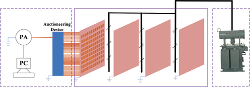
Figure 2. (a) Experimental set-up for the corona discharge of the ESP; (b) RS barbed electrode wire.

The current density distribution test system
shows the current density distribution test system. Specifically, the insulating film was first posted on the anode plate and then the cable welded with copper sheets passed through the holes that were made in advance on the anode plate. Thus, the current signal would be collected by the copper sheets and transmitted to the signal receiver. The signal receiving unit consisted of 119 copper sheets (10 mm × 30 mm × 1 mm) is configured on the anode plate as the measuring points. After the high-voltage power supply runs continuously and stably, the current value signal at each point is measured by the Keithley-6485 Picoammeter, which is used to measure the current of 0.1 nA accurately.
The data collection adopts the switching method. To avoid signal interference, the optocoupler relay and the triaxial shielded cable are used. Each signal transmission line is grounded, and the grounding is performed before each signal switching to release the static electricity on the line and prevent static electricity from damaging picoammeters.
The structure and arrangement of RS barbed electrode wire
In many electrostatic processes, parallel wire electrode arrangements are widely used to generate corona discharges. The RS barbed electrode wire is a type of corona discharge electrode that has been applied to more than 1000 ESPs. The RS barbed electrode wire consists of a steel tube support and several barbed electrodes spaced 100 mm apart, as shown in . The barbed wire is cold rolled from 0.7 mm thick steel plate. The sectional and 3D diagrams are shown in , respectively. The tip radius of the barbed electrode is 0.35 mm.
Experimental results and discussion
Experiment with a discharge electrode frame
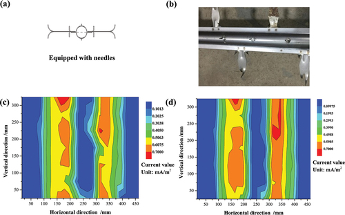
In , the electrode configuration with RS barbed electrodes wire and a 480 C type dust collector electrode plate is used as the basic unit of the ESP, which is a common configuration for many industrial applications. Meanwhile, the RS barbed electrodes wire were fixed to square steel frames in the vertical direction (y-axis) and every two frames were separated by 500 mm in the horizontal direction (x-axis). The distance between anode and cathode is 200 mm and the discharge electrode frame is on both sides of the RS barbed electrode discharge. The tip of barbed wire directly faces the 480 C type dust collector electrode plate, and the coordinate positions are (185, 75), (185, 175), (185, 275), (315, 25), (315, 125), (315, 225), (315, 325). The ESP channel is 3000 mm long, 200 mm wide and 4000 mm high.
Figure 3. (a) and (b) electrode configuration of ESP with single RS barbed cathode electrode, frame and an 480 C type dust collector electrode plate; (c) Current density distribution of the electrode plate at −46 kV; (d) Current density of the electrode plate at different applied voltages.
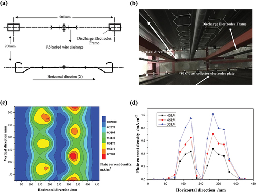
When the corona voltage is −46 kV, the electrode plate’s current density distribution can be obtained by calculating the copper sheet’s current value. The current density distribution cloud chart of the electrode plate under the two corona wires’ corresponding working conditions. It can be seen from that the current on the plate is almost zero on two sides of the 480 C type dust collector electrode plate and in the middle of the dust collector electrode plate. It indicates that the spike discharge is restrained by frames and the supporting tube. The zero-plate current is usually known as the corona shield (Arif et al. Citation2018; Kasdi Citation2016). As shown in , the current density distributions are comparable across a range of applied voltages; however, the corona shield is still present at the corresponding position. This suggests that different secondary voltage values will produce corona shielding and voltage is not the cause of corona shielding.
Double RS barbed electrodes wire
To investigate the mechanism of the corona shield that was discovered in the experiment and avoid the influence of the single set of barb wire electrode on the current density distribution’s inhomogeneity. One set of additional RS barbed electrode wire was arranged during the experiment. depicts an electrode configuration using two sets of RS barbed electrode wire with a distance of 225 mm and a single 480 C type dust collector electrode plate.
Figure 4. (a) and (b) Electrode configuration with double RS barbed electrodes wire; (c) Current density distribution on the collecting plates under the condition of double RS barbed electrodes wire.
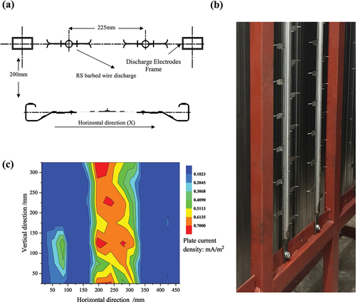
shows that the current density distribution shape dramatically changed after the addition of one more set of RS barbed electrode wire. The initial two weaker current density peaks for the single set of RS barbed electrode changed into a stronger current density peak in the middle of the dust collector electrode plate after arranging a double RS barbed electrode wire. Besides, the phenomenon of the corona shield disappeared accordingly. However, the current density of the plate was almost zero on two sides of the 480 C type dust collector plate electrode. Compared with the single set of RS barbed electrode wire tests, the low current density regions become large. By analyzing the current density distribution diagram of the electrode plate, it can be found that there is a maximum current density when X is in the range of 175 to 325 mm, which corresponds to the discharge tip on the inside of the prick piece. The current density has been superimposed and enhanced. The interaction between the discharge tip and the fixed frame resulted in extremely low current density near X = 75 and 425 mm. Therefore, the addition of more barbed electrode wire can not improve the current density distribution uniformly. The corona shielding effect of frames still exists. To prove this guess, the experiment without discharge electrode frames needs to be carried out.
Experiment without discharge electrode frame
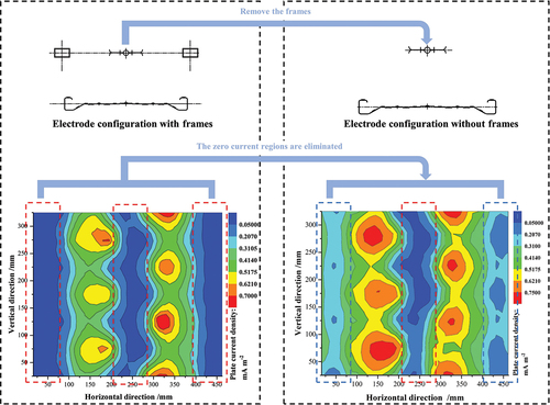
The shielding characteristics of the frames were investigated after the addition of one more set of RS barbed electrode wire to the test system. From the measured current density distribution of the electrode plate, it is found that there is still a zero current zone at the edge of the plate. To further study the mechanism of the non-uniform distribution of the current density on the collecting plates, an experiment without discharge electrode frames was conducted, as shown in . It can be clearly seen from the figure that the current density distribution has changed dramatically. By analyzing the measured data, it can be found that there are obvious improvements in the current density when X is below 75 mm and over 425 mm. Those results indicate that the corona shield of the discharge electrode frames was gone, and the current on two sides of the 480C type dust collector electrode plate appeared. Through comparison of , those experimental results proved that the cause of the corona shield on two sides of the 480C type dust collector electrode plate was the influence of the discharge electrode frame. shows the more uniform current density distribution and the peak plate current density appeared at more positions of the 480 C electrode plate compared with that in . Thus, better efficiency can be obtained after the improvement. In addition, the region of the corona shielding effect extends about 100 mm along the horizontal direction, as shown in . Therefore, it is clear that the corona shielding effect exists in the discharge electrode frame.
Figure 5. The current density distribution changes on the collecting plates under the condition of RS barbed electrode wire with and without discharge electrodes frame (the applied voltage: 46 kV).
However, the mid region of the plate that used to have low current density has just been slightly improved, which means the tube supports of barbed electrode wire still cause corona shielding. Some scholars installed additional needles on the support tube to improve the current density (Chen et al. Citation2021). In , some additional needles were installed on the tube support. The length of the awn thorn’ tip is 2 mm or 4 mm. and the distance between the adjacent auxiliary needles is 50 mm. It was found that there was almost no corona current in the middle and on the two outsides of the electrode plate. As shown in , adding 2 mm or 4 mm auxiliary needles to the tube support does not significantly increase the current density at the corresponding plate of the supporting circular tube. This indicates that the shielding effect has not been reduced.
Figure 6. (a) and (b) RS barbed electrode wire equipped with needles; (c) the current density distribution changes on the collecting plates under the condition of additional needles on the tube support (the applied voltage: 46 kV).
Comparison study of the shielding effect in the practical application of dust collection
The ESP with the electrode configuration of RS barbed electrode wire fixed on frames and a 480 C type dust collector electrode plate is one of the main forms. To verify the results obtained in the test system, we observed several practical engineering application ESPs. Some relevant phenomena were compared with the experiment results. shows the dust particles collected on the 480 C type dust collector electrode plate in the ESP’s shut-down state. It shows very clearly that the dust particles were clustered at the specific position where the plate current density was distributed, which is highly consistent with the phenomenon in . There was no dust collected on the collector electrode plate, where the current density was zero.
Figure 7. The real dust collection effect under the condition of RS barbed electrode wire with (a) and without (b) discharge electrodes frame.
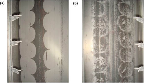
The actual project validated the relationship between the current density distribution and the dust collected on the collecting plates. That is, high current density leads to high dust collection and low current density leads to low dust collection. Due to the shielding effect on corona discharge by frames, the area that has a low current density would be ineffective for collecting dust.
Optimizations of the frame arrangements
The dust escape route caused by the shielding effect on corona discharge by the frame
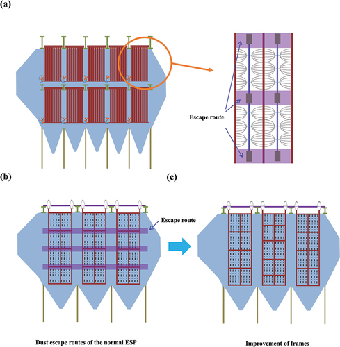
The frames of cathode systems in ESPs, in general, consist of the horizontal frames and the vertical frames. As shown in , the discharge electrodes were fixed to the horizontal frames. The corona shielding effect area of the discharge electrode frames on two sides was about 200 mm. In this case, the corona shielding effect also existed in the horizontal discharge electrode frames. Therefore, some space areas where there is no ion charge would lead to some of the particulate matter escaping from ESPs. In other words, particulate matter escape routes existed in the normal ESP. Due to the particulate matter, it could not be collected if it was uncharged in the ESP. As shown in , the frames of the cathode system in ESPs are usually arranged at the same level for consistency of structure and simplicity of design. Thus, the particulate matter would easily flow through the entire ESP.
Figure 8. (a) Configuration of the normal ESP; (b) Dust escape routes of the normal ESP; (c) Split-level frames of the developed ESP.
Improvement of frame arrangements
In the analysis of the shielding effect on corona discharge by frames, it was found that the shielding effect is caused by the interaction between the discharge wires and the frames. This has a profound effect on the electric field distribution. To explore the solution, we made some improvements to the existing frame arrangement. Frames in the common ESP were arranged horizontally in one line and were simple in structure. However, as escape routes caused by the shielding effect of frames on corona discharge existed according to experimental results, each horizontal frame would form an escape tunnel () and the flue gas with a number of particles would go through the tunnel horizontally.
The structural improvements of the frame arrangements, known as split-level frames, are presented in . The escape route would form if frames in each electric field were set in one line. The split-level frame breaks the route so that the particles that were not charged in the first electric field would be charged in the next electric field due to the shield frames being staggered. Further, although the electric frames shield the corona discharge, the electric field strength in the area was still high, thus the particles that were charged in the front electric field would be collected in the next electric field, resulting in the elimination of the escape route through the whole ESP.
Conclusion
In this study, we took the current density distribution and the corona discharge frames as the objects of study. The effects of the barbed electrode and the corona discharge frames were also systematically investigated. Meanwhile, some improvements to the existing frame arrangement were also made, and the following conclusions were obtained:
The shielding effect of frames in electrostatic precipitators on the corona discharge was found by the experimental method and has been verified in actual projects.
It is found that the conventional cathode frame of an electrostatic precipitator has corona shielding, resulting in dust escape routes in ESP. To eliminate the dust escape routes, a new ESP with split-level frame arrangements was proposed.
Authorship contribution statement
Haibao Zhao: Investigation, Methodology, Writing—original draft. Gang Yang: Supervision. Jiadong Shen, Baiqian Liu, Ziqiang Lyu: Writing—review and editing.
Disclosure statement
No potential conflict of interest was reported by the authors.
Data availability statement
Available upon request.
Additional information
Funding
Notes on contributors
Haibao Zhao
Haibao Zhao, is a senior engineer in Zhejiang Feida Environmental Science & Technology Co., Ltd, and engages in the research of electrostatic precipitator and coal-fired flue gas pollutant treatment technology
Gang Yang
Gang Yang, is a research fellow at University of Nottingham Ningbo China, and focuses on the control technology of pollutants from coal fired flue gas.
Jiadong Shen
Jiadong Shen, is an associate professor at Tongji Zhejiang College, and focuses on mechanical design and manufacturing processes.
Baiqian Liu
Baiqian Liu, is a professor at the University of Science & Technology Beijing, specializing in clean combustion of coal, combustion pollution and environmental protection and development of low-grade iron ore fluidized bed roasting technology.
Ziqiang Lyu
Ziqiang Lyu, is a senior engineer in Zhejiang Feida Environmental Science & Technology Co., Ltd, and engages in the installation and management of electrostatic precipitator technology.
References
- Arif, S., D.J. Branken, R. C. Everson, H. W. J. P. Neomagus, and A. Arif. 2018. The influence of design parameters on the occurrence of shielding in multi-electrode ESPs and its effect on performance. J. Electrostat. 93:17–30. doi:10.1016/j.elstat.2018.03.001.
- Asano, K., Y. Fukada, and T. Yasukawa. 2008. Measurement of AC ion current from a corona ionizer using a faraday cage. J. Electrostat. 66 (5–6):275–82. doi:10.1016/j.elstat.2008.01.006.
- Chang, J.S., and A.A. Berezin. 2001. Neutralisation of static surface charges by a flow stabilized corona discharge ionizer in a nitrogen environment. J. Electrostat. 51-52:64–70. doi:10.1016/S0304-3886(01)00067-5.
- Chen, B., Y. Guo, H. Li, W. Zhou, and B. Liu. 2021. Discharge characteristic of barbed electrodes in electrostatic precipitator. J. Electrostat. 109:103528. doi:10.1016/j.elstat.2020.103528.
- Gao, W., Y. Wang, H. Zhang, B. Guo, C. Zheng, J. Guo, X. Gao, and A. Yu. 2020. Numerical simulation of particle migration in electrostatic precipitator with different electrode configurations. Powder Technol. 361:238–47. doi:10.1016/j.powtec.2019.08.046.
- Jędrusik, M. 2017. Reduction of PM2.5 particle emission by electrostatic precipitator. Przegląd Elektrotechniczny 1 (2):221–25. doi:10.15199/48.2017.02.48.
- Jędrusik, M., A. Świerczok, and A. Jaworek. 2013. Collection of low resistivity fly ash in an electrostatic precipitator. J. Phys. Conf. Ser. 418:012069. doi:10.1088/1742-6596/418/1/012069.
- Jian, H., X. Guosheng, and Y.G. Zhou Xiaode. 2009. Law of V-I character of electrostatic precipitator. Chinese J. Environ. Eng. 3:143–46.
- Kasdi, A. 2016. Computation and measurement of corona current density and V–I characteristics in wires-to-plates electrostatic precipitator. J. Electrostat. 81:1–8. doi:10.1016/J.ELSTAT.2016.02.005.
- Liang, Y., Q. Li, X. Ding, D. Wu, F. Wang, T. Otsuki, Y. Cheng, T. Shen, S. Li, and J. Chen. 2020. Forward ultra-low emission for power plants via wet electrostatic precipitators and newly developed demisters: Filterable and condensable particulate matters. Atmos. Environ. 225:117372. doi:10.1016/J.ATMOSENV.2020.117372.
- McKinney, P.J., J.H. Davidson, and D.M. Leone. 1992. Current distributions for barbed plate-to-plane coronas. IEEE Trans. Ind. Appl. 28 (6):1424–31. doi:10.1109/28.175297.
- Noll, C.G. 2000. Balanced static elimination in variable ion mobility environments. J. Electrostat. 49 (3–4):169–94. doi:10.1016/S0304-3886(00)00017-6.
- Ohsawa, A. 2005. Modeling of charge neutralization by ionizer. J. Electrostat. 63 (6–10):767–73. doi:10.1016/j.elstat.2005.03.043.
- Parker, K. 2003. Electrical Operation of Electrostatic Precipitators. 1st ed. London: IET.
- Perera, F.P. 2017. Multiple threats to child health from fossil fuel combustion: impacts of air pollution and climate change. Environ. Health Perspect. 125 (2):141–48. doi:10.1289/EHP299.
- Robinson, M. 1967. A modified Deutsch efficiency equation for electrostatic precipitation. Atmos. Environ. 1 (3):193–204. doi:10.1016/0004-6981(67)90001-7.
- Tabti, B., L. Dascalescu, M. Plopeanu, A. Antoniu, and M. Mekideche. 2009. Factors that influence the corona charging of fibrous dielectric materials. J. Electrostat. 67 (2–3):193–97. doi:10.1016/j.elstat.2009.01.047.
- Talaie, M.R. 2005. Mathematical modeling of wire-duct single-stage electrostatic precipitators. J. Hazard. Mater. 124 (1–3):44–52. doi:10.1016/j.jhazmat.2005.01.007.
- Wang, X., J. Chang, C. Xu, P. Wang, L. Cui, and C. Ma. 2016. Electrical characteristics of electrostatic precipitator with a wet membrane-based collecting electrode. J. Electrostat. 80:85–94. doi:10.1016/j.elstat.2016.02.003.
- Wang, Y., H. Zhang, W. Gao, L. Shao, Z. Wu, Z. Zhao, C. Ge, D. Hu, C. Zheng, and X. Gao. 2021. Improving the removal of particles via electrostatic precipitator by optimizing the corona wire arrangement. Powder Technol. 388:201–11. doi:10.1016/J.POWTEC.2021.04.087.
- Yang, Z., P. Ji, Q. Li, Y. Jiang, C. Zheng, Y. Wang, X. Gao, and R. Lin. 2019. Comprehensive understanding of SO3 effects on synergies among air pollution control devices in ultra-low emission power plants burning high-sulfur coal. J. Clean. Prod. 239:118096. doi:10.1016/j.jclepro.2019.118096.
- Zheng, C., Y. Wang, Y. Liu, Z. Yang, R. Qu, D. Ye, C. Liang, S. Liu, and X. Gao. 2019. Formation, transformation, measurement, and control of SO3 in coal-fired power plants. Fuel 241:327–46. doi:10.1016/J.FUEL.2018.12.039.