
Abstract
The problem of the existence of the asthenosphere for old Precambrian cratons is still discussed. In order to study the seismic lithosphere–asthenosphere boundary (LAB) beneath the Baltic Shield, we used records of nine local earthquakes with magnitudes ranging from 2.7 to 5.9. To model the LAB, original data were corrected for topography and Moho depth using a reference model with a 46-km-thick crust. For two northern events at Spitsbergen and Novaya Zemlya, we observe a low-velocity layer, 60–70-km-thick asthenosphere, and the LAB beneath Barents Sea was found at depth of c. 200 km. Sections for other events show continuous first arrivals of P-waves with no evidence for “shadow zone” in the whole range of registration, which could either be interpreted as the absence of the asthenosphere beneath the central part of the Baltic Shield, or that the LAB in this area occurs deeper (>200 km). The relatively thin low-velocity layer found beneath southern Sweden, 15 km below the Moho, could be interpreted as small-scale lithospheric heterogeneities, rather than asthenosphere. Differentiation of the lower lithosphere velocities beneath the Baltic Shield could be interpreted as regional heterogeneity or as anisotropy of the Baltic Shield lithosphere, with high velocities approximately in the east–west direction, and slow velocities approximately in the south–north direction.
Introduction
The moving lithospheric plates are crucial elements in global plate tectonics. The lithosphere (from the Greek: λίθ°ς – rock) is understood as an outer shell of the Earth, which consists of the crust and a certain part of the upper mantle. Rigid lithosphere, sometimes called the “lid”, is underlain by ductile asthenosphere (from the Greek: ασθϵνώς – weakly).
Petrological studies of xenoliths and thermal modelling based on heat-flow measurements allow determination of the temperature gradients in the lower lithosphere, give an idea on the composition of the lithosphere and place constraints on the depth of the transitional zone between the lithosphere and the asthenosphere. The lithosphere–asthenosphere boundary (LAB) is not a sharp discontinuity, but rather a gradual and wide transition zone (see e.g. Meissner Citation1986). From the point of view of elastic properties and seismic velocities, the asthenosphere was identified as a low-velocity channel in the 50–200 km depth range in Gutenberg's (Citation1959) global model of the Earth. Low seismic velocities, or lowering of the velocity gradients with depth, in the upper mantle have also been found in regional scales beneath continents and oceans (e.g. Anderson & Toksöz Citation1963; Johnson Citation1967; Schubert et al. Citation1976; Grad Citation1988; Bruneton et al. Citation2004; Rychert et al. Citation2005, Citation2010; Gorman et al. Citation2006; Rondenay et al. Citation2009). The LAB depth strongly depends on temperature; the thicker lithosphere up to c. 200 km is clearly observed under “cold” Precambrian shields and platforms, while the thinnest lithosphere, of 50–100 km, is found under “hot” oceans and oceanic and continental rifts. Recently, the LAB depth have been effectively estimated from velocity variations in global and regional tomography models, group velocities of long period (c. 100 s) surface waves and S-wave receiver functions (e.g. Bruneton et al. Citation2004; Gregersen et al. Citation2006; Li et al. Citation2007; Pasyanos Citation2010; Wilde-Piórko et al. Citation2010). The LAB may also correlate with a downward extinction of seismic anisotropy or a change in the anisotropy direction (e.g. Eaton et al. Citation2009; Plomerová & Babuška Citation2010). The asthenosphere could be identified as a low-viscosity zone and a low value of the quality factor, QS (e.g. Stacey Citation1969; Karato Citation2010). However, the composition of the mantle in the pressure–temperature space could also affect on the low-velocity zone. For example, 3D modelling of S-wave velocity beneath the Baltic Shield showed significant lateral heterogeneity across the region, interpreted to arise from compositional variations within the lithospheric mantle (Bruneton et al. Citation2004). Characteristic for asthenosphere is low seismic activity or even total lack of earthquakes.
The electrically defined LAB is marked by a significant reduction in electrical resistivity, where resistive lithosphere is overlying the highly conductive asthenosphere. The asthenosphere, identified as a high conductivity layer (low resistivity layer) in the upper mantle, often coincides with a seismic low-velocity zone (e.g. Martinec & Wolf Citation2005; Korja Citation2007; Eaton et al. Citation2009).
The lithosphere may also be defined thermally. The use of borehole heat-flow measurements allows calculation of the lithospheric geotherms and estimation of the thermal lithosphere thickness, defined as the depth where the continental geotherms intersect the 1300°C mantle adiabat (e.g. Artemieva & Mooney Citation2001; Artemieva Citation2007).
The upper and lower boundaries of the asthenosphere appear to be gradient zones rather than first-order discontinuities. This suggests that we should not expect large contrasts of elastic parameters that would produce strong reflected and converted phases, and that seismic reflection and receiver function techniques may not be optimal in this context. Instead, surface wave methods, seismic tomography and searching for “shadow zones” of P and S body waves appear to be the most promising methods for the determination of the seismic LAB depth.
In this paper, we are using a relatively conventional approach – the “refraction” method, which permits the determination of layer thicknesses (lithosphere) and velocities in order to resolve the depth of the LAB. For a LAB depth of 100–200 km, “shadow zones” are expected at epicentral distances of about 1500–2000 km. For studying the “shadow zones”, local seismic events with relatively big magnitudes, which produce good quality records at long distances from the source, can be used (Fig. ).
The Baltic Shield and previous seismic investigations of the lithosphere and the LAB
The East European Craton (EEC) is the coherent Precambrian part of Europe, mainly of Archaean and Palaeoproterozoic ages, assembled in the Late Palaeoproterozoic (Bogdanova et al. Citation2005, Citation2006). In the southwest, the EEC is limited by accreted Phanerozoic terranes of the Trans-European suture zone (TESZ), which extends from the British Isles to the Black Sea region. The northeastern part of the European continent occupies the Baltic (also Fennoscandian) Shield with the Precambrian bedrock exposed on the Earth's surface (Figs. and ).
The typical three-layer crust of the Baltic Shield has a thickness in the range of 42–60 km and attains its maximum thickness in Central Finland (Grad & Luosto Citation1987; Luosto Citation1997). The P-wave velocities in the upper crust are 6.0–6.4 km s− 1, in the middle crust 6.6–6.9 km s− 1 and in the lower crust >7.0 km s− 1. The thickness of upper and middle crusts is in the range of 32–42 km. The thickness of the lowermost high-velocity crustal layer is in the range of 4–24 km. The P-wave velocity in the uppermost mantle is 7.9–8.2 km s− 1. The ratio of P-wave velocity to S-wave velocity varies typically from 1.67–1.70 in the upper crust to 1.77–1.80 in the lower crust. In the upper mantle, the ratio is c. 1.73 (e.g. Guggisberg Citation1986; Grad & Luosto Citation1987; Luosto Citation1997; Hyvonen et al. Citation2007).
Similar to other old Precambrian cratons, features of the asthenosphere beneath the Baltic Shield are still discussed (e.g. Artemieva Citation2003; Bruneton et al. Citation2004; Kozlovskaya et al. Citation2008). The first determinations of the lithospheric thickness beneath the Baltic Shield were obtained from analyses of fundamental-mode and higher order Rayleigh surface waves. Dispersion of the higher mode data has been interpreted by Nolet (Citation1977) to distinguish the thick lithosphere of the Baltic Shield from the thinner Western European lithosphere (see also Zielhuis & Nolet Citation1994). With the use of higher modes, Cara et al. (Citation1980) found no need for a low-velocity zone in the mantle beneath the northern Eurasia. They also argue that a nearly constant 4.5–4.6 km s− 1 S-wave velocity is required in the uppermost 200 km. Using Rayleigh-wave dispersion data for the Fennoscandian region, Calcagnile (Citation1982) found lid thicknesses of up to c. 135 km in the area from Bothnia to north-central Finland with a weak, if any, shear velocity contrast to the underlying layer. The surrounding areas are characterized by lid thicknesses of up to c. 75 km only. A stronger low-velocity zone with a lid contrast of 0.25–0.45 km s− 1 may be found in the Caledonian and the Baltic Sea area (Calcagnile Citation1982). An updated map of the lithosphere–asthenosphere system in the Europe (Panza Citation1985; Calcagnile & Panza Citation1987) shows much larger lithospheric thicknesses of the Baltic Shield, in the range of 110–170 km, increasing to >190 km in its central part. The Baltic Shield model obtained later by Dost (Citation1990) shows an absence of the low-velocity layer, while density seems to be lower at 200–350 km depth.
The deep structure of the lower lithosphere and asthenosphere can also be investigated from studies of P-waves. From the explosive source refraction profile FENNOLORA, Guggisberg (Citation1986) interpreted several deep low-velocity channels (with about 5% decrease in P-wave velocity in a few tens of kilometres thick layers) in the lower lithosphere, with the bottom of the lithosphere at about 200 km depth marked by a velocity change of a couple of per cent. Regional 1D S-wave velocity models for the central part of the Baltic Shield, obtained from the SVEKALAPKO array (Kozlovskaya et al. Citation2008), show that velocities beneath the craton are significantly higher (about 4% down to a depth of 250 km) compared with standard model iasp91 (Kennett & Engdahl Citation1991). On the other hand, lowering of the velocity with depth is not visible (Kozlovskaya et al. Citation2008). This fact could be interpreted as an absence of asthenosphere, or that the LAB in this area occurs deeper. Plomerová & Babuška (Citation2010) define the LAB as a boundary between fossil anisotropy in the lithospheric mantle and underlying seismic anisotropy related to present-day flow in the asthenosphere. The LAB topography is more distinct beneath the Phanerozoic part of Europe than beneath its Precambrian part. Beneath the central Fennoscandia, the LAB deepens down to c. 220 km (Plomerová & Babuška Citation2010).
Seismic data for the Baltic Shield
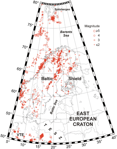
Central and Northern Europe are characterized by weak–to-moderate seismicity (e.g. Slunga Citation1991; Ahjos & Uski Citation1992). The map in Fig. shows locations of 2698 events recorded from January 2008 to September 2011 in the Baltic Shield and its surroundings. Most of these events were classified as earthquakes. Events recorded at less than three stations, as well as explosions from known sites, were omitted from the data-set. Mining-induced seismic events (e.g. rock bursts, mine collapses) were also excluded. However, it is likely that some man-made events still exist in the data, especially among low-magnitude events (Uski & Raime Citation2010). It should be mentioned that the actual distribution and concentration of events is based on the properties of the network deployed to detect them, particularly in the case of small events.
Fig. shows that seismic events are concentrated in a few distinct areas. In the north (18–20°E, 77–78°N), a group of events is concentrated in the southern part of Spitsbergen, within continental crust of the Barents Sea block (see also Figs. and ). West of 10°E and north of 73°N, a linear group of epicentres is related to the Knipovich Ridge and Mohns Ridge segments of the Mid-Atlantic Ridge. Events south of this group are related to continent–ocean transition (COT) between oceanic crust of the Atlantic and continental crust of the Barents Sea. The coastal area of Scandinavia is characterized by moderate seismicity of the Caledonides. In the southern part of the study area (6–8°E, 50–52°N), a group of events is related to seismic activity of young continental rifting – in the Rhine Graben. Events occurring around 16°E and 52°N are related to copper mining activity in Lubin in southwestern Poland. There are both natural and induced earthquakes in this area. Events in the area around 19°E and 50°N relate to coal mining activity in Silesia (Draber et al. Citation2002).
The Baltic Shield in general is a stable intraplate region characterized by weak-to-moderate seismicity, with event magnitudes rarely exceeding 4.0. The majority of earthquakes occurs within the Kuusamo–Kandalaksha region in the northeastern Finland and adjacent Russia (28–35°E, 65–68°N), and along a broad north–south trending belt running parallel to an ancient plate boundary from the Bothnian Bay to northern Norway (from 18°E, 63°N to 25°E, 70°N; Ahjos & Uski Citation1992). The Kuusamo area is the area where natural earthquakes are the most frequently recorded in Finland. However, they are rather weak, and most of them are detected only because of the local seismic array in this area (Fig. ). In the southern part of the Baltic Shield, an area of low seismicity in Skåne (11–14°E, 55–57°N) has some relatively strong (with magnitudes up to 5) events. In the Fennoscandian area, 80–90% of all earthquakes occur in the uppermost 20 km of the Earth's crust (Slunga Citation1991; Ahjos & Uski Citation1992). Earthquakes at depths of 40 km and deeper are rare. However, some well-determined events in northern Sweden have been located close to the crust–mantle boundary (Arvidsson & Kulhanek Citation1994; Arvidsson Citation1996). These observations suggest that the Archaean lower crust may be seismically active and involved in brittle deformation (Uski et al. Citation2012).
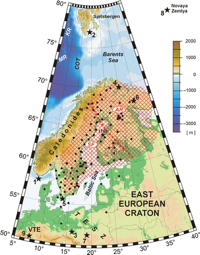
To study the lithosphere–asthenosphere system of Fennoscandia, we need relatively powerful sources (earthquakes or quarry blasts) generating seismic waves that can be recorded up to a distance of at least 2000 km. In the first step of event selection, we chose the strongest events that occurred within last years. We chose to use fairly recent events since this will enable us to use data recorded by stations of the Swedish National Seismological Network (SNSN), a dense regional seismic network of broadband stations allowing good quality records of local events (e.g. Olsson Citation2007). The number of the SNSN stations has grown rapidly in the last decade, and today the network has a good coverage of most of Sweden. Because of the size of the Baltic Shield (about 1500 km in diameter), we limited our data-set to events from the outskirts of the shield in order to obtain large enough station-to-event distance range. The nine events chosen are listed in Table and shown in Fig. (event no. 8 at Novaya Zemlya is located outside the map frame). The magnitudes of the events are in the range of 2.7–5.9. Exception is the small event no. 10 (magnitude 1.1) in western Finland, which occurred nearly at the same time as event no. 9 in the Rhine Graben (both events were recorded simultaneously). In Fig. , earthquakes are marked by black stars with numbers and the seismic stations providing the data are marked by black dots.
Table 1 Events used for lithospheric structure studies in the Baltic Shield area.
Average velocities, reference model and time corrections
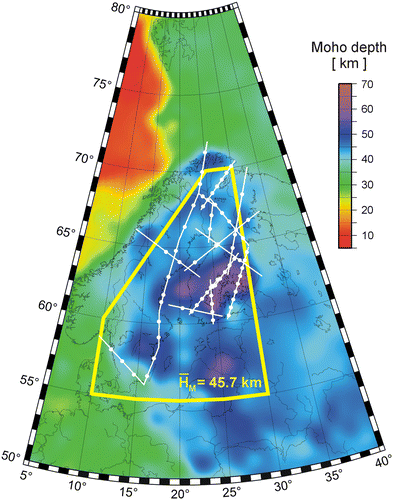
To determine the seismic velocity structure of the lithosphere and the LAB depth beneath the Baltic Shield, we studied travel times of local earthquakes. The relatively large number of permanent seismic stations in the Baltic Shield permits for relatively dense recording of the events, with 30–100 km distance between the stations. This spacing is sufficient in the LAB studies as the penetration depth of body waves is a few hundreds of km and the wave length is in the order of a few kilometres. Recording stations are not linearly aligned, which would have permitted for easy 2D interpretation of the structures along the profile, but scattered in a wide corridor of a few hundreds of kilometres width. This means that two stations at similar epicentral distance may lie at locations with significantly different altitudes and Moho depths. To model the lower lithosphere and asthenosphere, the original data need to be time-corrected for topography and Moho depth variation for each event and each station location. Topography for seismic station locations changes from close to sea level up to 630 m (see Fig. ).
Differences in the Moho depth in the study area are significant. As seen from Fig. , the Moho depth in the Baltic Shield is varying of 30–60 km (Grad et al. Citation2009). An average Moho depth was calculated for the area within the yellow frame shown in Fig. , using data from the digital Moho depth map by Grad et al. (Citation2009). The average depth is 45.7 km, and in the reference model a value of 46 km depth was used. P-wave velocities in the reference model were compiled from seismic studies in the area. In Fig. , the investigated profiles are shown by white lines (Hirschleber et al. Citation1975; Lund Citation1979; Guggisberg Citation1986; Luosto Citation1986; Grad & Luosto Citation1987; Luosto et al. Citation1989, Citation1990, Citation1994; Grad et al. Citation1991; FENNIA Working Group Citation1998; Uski et al. Citation2012; Tiira et al. Citation2014) and places of sampled velocities are shown by white dots. All velocity–depth relations were sampled at 1-km depth intervals. The velocity values were weighted according to reliability of the models. The highest weight was given to data from modern refraction and wide-angle reflection profiles with a dense system of observations and good reciprocal coverage, e.g. SVEKA (Grad & Luosto Citation1987), BALTIC (Luosto et al. Citation1990) and POLAR (Luosto et al. Citation1989). Velocity in the crust and uppermost mantle was directly extracted from 2D numerical models with a spacing of 60 km along profiles. Only parts of models sufficiently sampled by rays were used in velocity–depth analysis. Published 1D models were adopted for older profiles with a sparse system of observations, e.g. Blue Road (Lund Citation1979), FENNOLORA (Guggisberg Citation1986) and Sylen-Porvoo (Luosto Citation1986).
P-wave velocities in the crust and uppermost mantle of the Baltic Shield were sampled in 67 locations (white dots in Fig. ). Comparison with location of seismic stations (Fig. ) shows a good coverage for the entire Baltic Shield. In total, 4269 values of velocity were used for the determination of average velocity–depth relations in the crust and uppermost mantle. The data were fitted by linear functions:
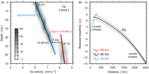
Travel times for the reference model are shown by the black line in Fig. (b). For comparison, two travel time curves for shallower Moho (34 km depth, blue line) and deeper Moho (58 km depth, red line) are shown. Time differences are about ± 2 s at distances between 300 and 500 km, decreasing to about ± 1 s at distances of 1000 to 1500 km. Travel times were calculated with 1-km intervals for Moho depths from 34 to 58 km. The time corrections were calculated using interpolation for both distances and the Moho depths below the event and station. In the modelling of each event, we used “true” depth of the event, making correction only for the Moho depth (difference between the depth of the event and the Moho depth). The final time corrections included also the correction for topography.
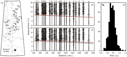
An example of the application of time corrections is shown in Fig. . The map in Fig. (a) shows the location of event no. 3 (Lubin; marked by black star) and seismic stations (black dots) with their numbers. Corresponding sections with and without corrections are shown in Fig. (b),(c), respectively. Red dots are picks of first arrivals (the same picks are shown in both sections). Red lines are travel times and grey bands show scattering of the data. Application of the time corrections improves correlation. The scattering of first arrivals is about 1 s for the section with the time corrections (Fig. (b)), and about 2 s for the section without corrections (Fig. (c)). The histogram in Fig. (d) shows the distribution of 604 total time corrections. About 93% of the corrections are in the range from − 0.1 to 0.8 s, with a maximum for the 0.2–0.5 s interval (282 corrections). Such a processing sequence was applied for all sections in this paper, which permits us to use a reference crustal model without topography (0 m above sea level) and with the reference Moho at 46 km depth. After applying the corrections, all sections correspond to Moho depth of 46 km and stations at sea level.
Searching for asthenosphere beneath the Baltic Shield
To study the LAB in the Baltic Shield, we chose nine events (Table , Fig. ) from the outskirts of the shield. For all record sections, time corrections were applied as described in the previous section. Poor-quality and noisy seismograms were removed from the sections. Some seismograms were also omitted to avoid crowding of seismograms from stations with similar epicentral distances. All record sections were normalized, filtered and drawn with a reduction velocity of 8 km s− 1 (in some cases with a reduction velocity of 4.5 km s− 1 for sections of S-waves).
Modelling of all sections in this paper was done using the ray-tracing technique and software SEIS83 (Červený & Pšenčík Citation1984). As a reference crustal model for P-wave velocity, we used the model described in the previous section. Crustal S-wave velocities were recalculated from P velocities using the relation VP/VS = 1.67 in the uppermost crystalline basement and VP/VS = 1.77 in the lower crust (see e.g. Grad & Luosto Citation1987; Bogdanova et al. Citation2006; Uski et al. Citation2012). The models of the mantle structure were derived by trial-and-error forward modelling. Travel times and synthetic seismograms were calculated for 1D models with Earth-flattening transformation for waves from a point source (Hill Citation1972). This transformation permits to calculate travel times for a flat model and transform for a spherical Earth.
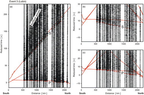
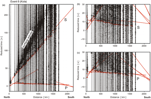
Two examples of the record sections for event no. 3 (Lubin) and for event no. 6 (Kola) are shown in Figs. and . Apart from the full wave fields of P, S and surface waves (Figs. (a) and (a)), enlarged parts of the sections are shown for S-waves (Figs. (b) and (b)) and P-waves (Figs. (c) and (c)). Red dots are the picked first arrivals of P- and S-waves, and red lines are the first arrivals of P- and S-waves calculated for the iasp91 model (Kennett & Engdahl Citation1991). Although the crustal thickness in the iasp91 model is only 35 km (in comparison with 46 km for the Baltic Shield), observed P and S arrivals are both significantly earlier than predicted by the iasp91 model – at a distance of 1700 km c. 3–4 s for P-waves and c. 6–8 s for S-waves. This is a clear indication that lithospheric P and S velocities beneath the Baltic Shield are higher than those of the iasp91 model. Also, the observed continuation of the first arrivals up to 1700–2000 km distance could be interpreted as a lack of a “shadow zone”. High lithospheric velocities for the EEC using Pn and Sn waves recorded at teleseismic distances were described nearly 50 years ago by Båth (Citation1966).
Sections with records up to 2200–3000 km distances are shown in Figs. and . For event no. 8 (Novaya Zemlya), good-quality first arrivals of P-waves are recorded in the distance range of 1300–3000 km. At an epicentral distance of about 1800 km, a clear “shadow zone” is visible (marked in Fig. by an arrow). Corresponding rays are shown in the ray diagram: red rays travelling in the lithosphere and navy blue rays reflected from the bottom of the asthenosphere and mantle including “410-” and “660”-km boundaries.
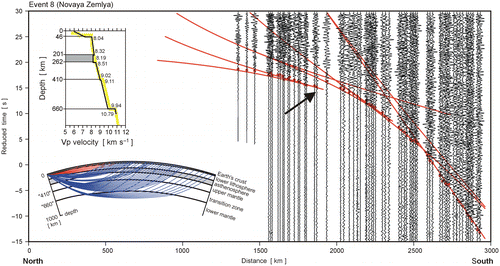
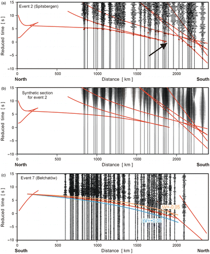
Also shown in Fig. is a comparison between the 1D velocity model for this event and the iasp91 model. An interesting observation is related to the frequency of the first arrivals. The lithospheric phases have significantly higher frequencies than the deeper phases and this change is observed at relatively short epicentral distance (compare section at distances 1900 and 2100 km). One explanation could be strong attenuation of high-frequency content for a pulse travelling through the asthenosphere. In such a case, the asthenosphere should be characterized by a lower value of the quality factor QP. A broad zone of low velocities and low values of QP was found beneath the FENNOLORA profile between depths of 100 and 160 km (Hauser & Stangl Citation1990; Stangl Citation1990).
For event no. 2 (Spitsbergen), good-quality P-waves are recorded in the distance range of 800–2400 km (Fig. ). First arrivals are far away from explosive character – a monotonic increase in amplitude to maximum of the seismic moment takes about 5 s (Pirli et al. Citation2010). In such a case, correlation of further arrivals is practically impossible. This is illustrated in Fig. (B) showing synthetic seismograms calculated for an extremely long-source pulse. However, because of the large magnitude of the event (M = 5.9), correlation of the first arrivals was unquestionable and was done manually using the software ZPLOT (Zelt Citation1994), which allowed flexible use of scaling, zooming, filtering and reduction velocity. For the two northern events at Spitsbergen and Novaya Zemlya, we observe a low-velocity layer, or asthenosphere. The LAB beneath Barents Sea was found at a depth of about 200 km (198 and 201 km for events no. 2 and no. 8, respectively).
The section for event no. 7 (Bełchatów) shows continuous first arrivals of P-waves with no evidence for a “shadow zone” in the whole range of registration (Fig. (c)). A lack of “shadow zone” could be interpreted as a lack of asthenosphere beneath central part of the Baltic Shield, or that the LAB occurs deeper in this area (>200 km).
For event no. 7 (Bełchatów), an example of the resolution test of calculated travel times is shown in Fig. (c). The arrival times of P-phase were calculated for the lower lithosphere (lid) model perturbed by +0.05 and − 0.05 km s− 1 relative to the final model (see red curve in Fig. (b)). Travel times shown by blue and orange lines are significantly too early and too late. This indicates that the average lid velocity could be determined with an accuracy better than ± 0.05 km s− 1. Uncertainties in the order of ± 0.05 km s− 1 are rather small, particularly if we compare it with the results of receiver function or teleseismic tomography. However, in our method, the seismic rays are travelling nearly horizontally in the lid and over long distances in the order of 1000–1500 km. In receiver function and teleseismic tomography studies, rays cross the lid nearly vertically with ray paths of about 200–300 km long only.
Models of the lower lithosphere structure
Our other data do not show evidence for the existence of the asthenosphere beneath the Baltic Shield. However, they contain information about the lower lithosphere heterogeneities, which could be deduced from P- and S-waves (Figs. ).
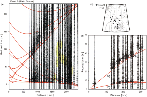
The sections shown in Fig. need more explanation. About 4 min (precisely 257.7 s) after event no. 9 (Rhine Graben, M = 4.0), at a distance of about 1800 km towards the northeast, a smaller earthquake occurred in western Finland (event no. 10, M = 1.1; see Table ). The section in Fig. (a) shows both events, recorded simultaneously. Phases attributed to the small event in Finland are highlighted in yellow (recorded at epicentral distances of 1500–2200 km from event no. 9). In Fig. (b)(c), the location of this event and the record section are, respectively, shown. Pg, Pn, Sg and Sn waves calculated for the reference model of the Baltic Shield fit observations quite well. For event no. 9 (Fig. (a)), strong P- and S-waves are recorded up to 1500 km distance. However, in the distance range 1600–2300 km, the strong P-waves have no corresponding strong S-waves. This fact could be interpreted as lowering of the S-wave velocity (the S-wave asthenosphere); another explanation could be lower quality factor for S-waves (“Qs asthenosphere”?).
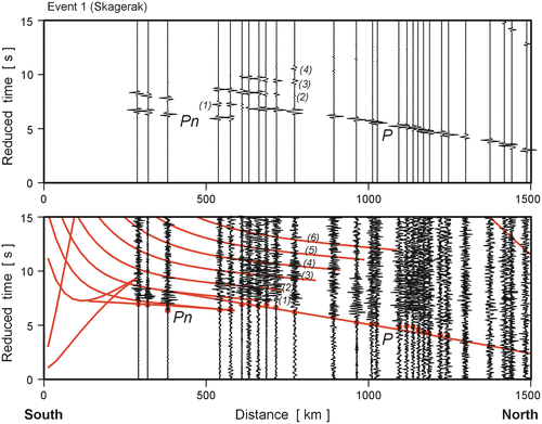
Lower lithosphere heterogeneities were interpreted beneath southern Sweden using data for event no. 1 (Skagerak). At a distance of c. 600 km, a small break in the continuity of the first arrivals of P-waves is observed (Fig. ). This can be explained by a model with a 16-km-thick low velocity layer (LVL) 15 km below the Moho and with a P-wave velocity drop of − 0.33 km s− 1. Such a velocity contrast is sufficient to explain the strong amplitudes, seen in the distance range of 1600–1800 km, as multiple reflections within the LVL. Red lines in Fig. show the first arrivals (Pn and P), reflection from the bottom of the LVL (1) and the travel times of five multiples in the LVL (2)–(6). In synthetic seismograms, reflection from the bottom of the LVL (1) and multiples (2) and (3) are strong, (4) is weak and higher multiples practically invisible. We do not interpret the LVL as the asthenosphere but as an inhomogeneity within the lower lithosphere.
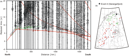
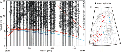
The next record section (Fig. (a)) illustrates a differentiation of the upper mantle velocities observed for the event no. 4 (Varangerfjord). Although time corrections have been applied, considerable scattering of the first arrivals is observed, particularly in the distance interval of 200–600 km. Later arrivals are marked in green and corresponding stations are also marked in green in the neighbouring map (Fig. (b)). Low velocities in the lower lithosphere coincide with the northern part of the Baltic Shield and “normal velocities” with the area towards the south (red dots). Even larger scattering of the first arrivals, up to about 3 s at about 800 km distance, is observed for event no. 5 (Skåne) shown in Fig. . In this case, the first arrival picks were split into three groups: normal arrivals to the north (red dots), faster to the northeast (light blue dots) and the fastest to the east (navy blue dots).
In the last two sections for event no. 4 (Varangerfjord) and for event no. 5 (Skåne), the thick grey bar highlights far-distance Pg waves recorded up to about 700 km distance (Figs. and ). This means, qualitatively, that attenuation of P-waves in the Baltic Shield crust is relatively low. Beneath the SVEKA profile in Finland (Grad & Luosto Citation1994), the QP-factor in the uppermost 1 km is only 50–80, but in the crystalline crust it reaches values of 500–800, which means that attenuation in the crust is extremely low.
The records of the last two sections (Figs. and ) reach distances up to about 1700 km, too short to reach the LAB in the central part of the Baltic Shield, where it is at depth deeper than 200 km. On the other hand, both events, located in the northern and in the southern parts of the shield, give valuable information about the lower lithosphere – lid. Based on these data, the Baltic Shield lid can be divided into areas of different P-wave velocities (Fig. (a)): normal velocity (approximately corresponding to the area of Sweden), faster velocities (central and southern Finland), the fastest velocities (at the southeastern edge of the shield) and the lowest velocities (coincides with the northern part of the Baltic Shield in northern Finland and northern Norway).
Summary of the upper mantle structure and comparison with other methods
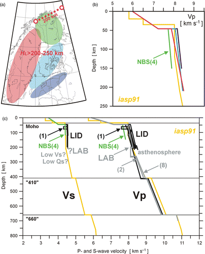
The seismic structure of the lithosphere–asthenosphere system beneath the Baltic Shield was studied using local earthquakes with magnitudes ranging from 2.7 to 5.9. Good-quality records were obtained up to 2200–3000 km distances by a relatively dense network of seismic stations, with a station spacing of 30–100 km. All the data were corrected for topography and Moho depth for each event and each station location, using a reference model of the Baltic Shield with 46-km-thick crust. A summary of the Baltic Shield structure is compiled in Fig. , which shows a map of the velocity provinces (Fig. (a)), P-wave velocities in the lid (Fig. (b)), and P- and S-wave velocities in the upper mantle (Fig. (c)).
In general, P and S arrivals observed in the Baltic Shield are significantly earlier than predicted by the iasp91 global velocity model, which clearly indicates that lithospheric P and S velocities of the Baltic Shield are higher (see Figs. (b),(c) and (b),(c)). On other cratons, velocities in c. 200 km deep lithosphere consistently reach on average about 5% higher values when compared with global averages (Eaton et al. Citation2009; Lebedev et al. Citation2009; Jones et al. Citation2010).
For the two northern events (Spitsbergen and Novaya Zemlya), we observe a LVL that we interpret as the asthenosphere. The LAB beneath Barents Sea was found at the depth of 198 and 201 km for event no. 2 (Spitsbergen) and for event no. 8 (Novaya Zemlya), respectively. The locations of the deepest points reached by rays in the lithosphere are shown in the map (Fig. (a)) by two red circles, and the red-dotted line shows an approximately 200-km isoline of the LAB depth. Other data show that LAB in the central Baltic Shield, if it exists, should be deeper than 200–250 km. These depths coincide with results of surface wave tomography of the Barents Sea and surrounding regions (Levshin et al. Citation2007), as well as thermal modelling of the EEC (Artemieva Citation2003, Citation2007). The asthenosphere thickness for the events at Spitsbergen and Novaya Zemlya was determined only from P-waves, and they are 69 and 61 km, respectively (see grey lines in Fig. (c)). Analysis of the other record sections shows that the first arrivals of P-waves are continuous in the whole range of registration, while corresponding S-waves are weaker. Weak S-waves can be explained by lowering the S-wave velocity or decreasing the quality factor for S-waves (S-wave asthenosphere or QS asthenosphere, it means a lower S-quality factor).
The thick lithosphere beneath the Baltic Shield was also found from teleseismic data recorded by broadband stations of the Swedish National Seismic Network. Using waves converted from S to P in the uppermost mantle, the LAB was clearly imaged at depths of about 200 km (Olsson et al. Citation2007). Beneath the Teleseismic Tomography across the Tornquist Zone in Germany–Denmark–Sweden (TOR) array, existence of a major near-vertical lateral change in the P and S velocities of several percents was observed up to depths of 250 km, more or less directly below the edge of the Baltic Shield (Shomali et al. Citation2006). Shomali et al. (Citation2006) conclude that there is no asthenosphere under the southern Baltic Shield area for which four possibilities can be considered: there may be no conventional asthenospheric layer; the base of the lithosphere is deep and is not resolvable based on the TOR data-set; the transition (LAB) is characterized with a small velocity change and resolution of the base of the model is low. A deep LAB has also been found for other cratons, e.g. beneath the Slave craton in the northwestern Canadian Shield (Chen et al. Citation2007). The 1D inversion of phase velocities yields high upper mantle S-wave velocities of 4.7 ± 0.2 km s− 1 that persist to 220 ± 65 km depth and thus define the cratonic lithosphere. The Rayleigh wave phase velocities at the period range of 20–142 s give the greatest sensitivity at depths of 28–200 km. The lithosphere is thinner beneath the eastern margin of the South Australia Craton. Prominent S-phases from a negative velocity contrast were found at depths of 131 ± 9 km, consistent with the LAB depth range derived from surface wave tomography (Ford et al. Citation2010).
From the analysis of record sections from different areas in the Baltic Shield, the lid of the shield can be divided into areas of different P-wave velocities. In Fig. (a), the area of normal velocity is marked in red (approximately corresponding to the area of Sweden), faster velocities in blue (central and southern Finland), fastest velocities in navy blue (at the southeastern edge of the shield) and the area of the lowest velocities is marked in green (coincides with the northern part of the Baltic Shield in northern Finland and northern Norway). The corresponding models of P-wave velocity are shown in the same colours in Fig. . Differentiation of the velocity could be interpreted as heterogeneity of the lid. However, another interpretation could be anisotropy of the lithosphere, with the fast velocity direction approximately in the east–west direction and the slow velocity direction approximately in the south–north direction.
The upper mantle structure under the Baltic Shield has also been studied using teleseismic P and S tomography and shear-wave splitting (Eken et al. Citation2007, Citation2008, Citation2010). The results indicate P-wave velocity perturbations of ± 3% down to at least 470 km below the SNSN. Below Central Sweden, where ray coverage is the best, the data reveal a large region of relatively low velocity at depths of c. 300 km. In the TOR experiment, joint analysis of shear-wave splitting parameters and the directional dependence of teleseismic P residuals show different lithosphere thicknesses and different orientations of seismic anisotropy in the mantle lithosphere. The three blocks separated by the major sutures are clearly differentiated by the orientation of large-scale olivine fabric in the mantle lithosphere. Fast velocities in the cratonic lithosphere of the southern Sweden domain are parallel to the craton edge (Babuška & Plomerová Citation2004; Plomerová & Babuška Citation2010).
Regional teleseismic tomography carried out within the SVEKALAPKO seismic experiment was designed to study the upper mantle of the Baltic Shield between the Archaean and Proterozoic domains (Bruneton et al. Citation2004). The 3D shear-wave velocity model obtained from the fundamental mode Rayleigh waves shows lateral variations in velocities down to 150 km depth. The model exhibits variations in the S-wave velocities up to ± 3%; however, they are not noticeably different beneath the Archaean and Proterozoic domains. As the thermal variations beneath this part of shield are very small, these lateral variations must be caused by different rock compositions.
Apart from regional velocity differentiation, we found small-scale lithospheric inhomogeneities. Beneath southern Sweden, 15 km below the Moho, a LVL of 16 km thickness with a − 0.33-km s− 1 drop of velocity for P-waves was found. Reflected waves and multiples in the LVL agree well with observations (Fig. ). For the same area of southern Sweden, a lithospheric reflector was found at a similar depth from FENNOLORA data (e.g. Guggisberg Citation1986), as well as in the uppermost mantle beneath southern Finland from local events registered by the SVEKALAPKO seismic array (Yliniemi et al. Citation2004). The analyses of data from the TOR experiment all show the Tornquist zone to be a sharp boundary throughout the lithosphere, with a lithosphere thickness of at least 200 km for the southernmost part of the Baltic Shield (Shomali et al. Citation2006).
Conclusions
The asthenosphere was found at a depth of c. 200 km in the area north of the Baltic Shield (beneath the Barents Sea).
No evidence was found for the asthenosphere beneath the Baltic Shield – it has to be deeper than 200 km, if it exists at all. Even if it exists at greater depths, it could not be detected by the “refraction” method. For distances larger than about 2000 km, a “shadow zone” in the first arrivals would be masked by deeper waves from the “410-” and “660”-km boundaries.
Difficulties in the interpretation of later arrivals result from the complicated source function of natural earthquakes (e.g. event no. 2) and from multireflections in the LVL (event no. 1). Interpretation can also be complicated by seismic noise when signals from distant earthquakes are not strong enough or obscured by simultaneous recording of small local events (see events no. 9 and 10).
Differentiation of the velocity in the lid could be interpreted as regional heterogeneity or anisotropy; however, more 3D tomographic studies are required.
Acknowledgements
The authors thank Finnish Academy of Science and Letters, Väisälä Foundation, for financial support. This work was partially supported by NCN grants UMO-2011/01/B/ST10/06653 and DEC-2011/02/A/ST10/00284. The authors are also grateful to the staff at the SNSN for giving the authors access to their data. Waveform data from seismic stations operated by the Institute of Seismology of the University of Helsinki, the Sodankylä Geophysical Observatory of the University of Oulu and from the SNSN were used in this study. For specific events, data from Norwegian and Russian stations were made available by the Bergen Seismological Observatory and NORSAR in Norway. The authors wish to thank GEOFON, GFZ German Research Centre for Geosciences for earthquake information and waveform data. The authors also thank two referees, Prof. C. Juhlin and Prof. R.W. England, for their helpful comments. The authors are grateful to Dr Emilia Koivisto and editor Dr Magnus Ripa for improving the English language. Geographic data handling and plotting were done with the GMT software by P. Wessel and W.H.F Smith (Wessel & Smith Citation1991, Citation1998).
Notes
* Current affiliation: Department of Mineral Resources, Geological Survey of Sweden, P.O. Box 670, SE-75128 Uppsala, Sweden
References
- Ahjos, T. & Uski, M., 1992: Earthquakes in northern Europe in 1375–1989. Tectonophysics207, 1–23. Updated catalogue (1375-2008). Available at: http://www.seismo.helsinki.
- Amante, C. & Eakins, B.W., 2009: ETOPO1 1 arc-minute global relief model: procedures, data sources and analysis. NOAA Technical Memorandum NESDIS NGDC-24, 19 pp.
- Anderson, D.L. & Toksöz, M.N., 1963: Surface waves on a spherical Earth. 1. Upper mantle structure from Love waves. Journal of Geophysical Research68 (11), 3483–3500.
- Artemieva, I.M. & Mooney, W.D., 2001: Thermal thickness and evolution of Precambrian lithosphere: a global study. Journal of Geophysical Research106 (B), 16387–16414.
- Artemieva, I.M., 2003: Lithospheric structure, composition, and thermal regime of the East European Craton: implications for the subsidence of the Russian platform. Earth and Planetary Science Letters213, 431–446. 10.1016/S0012-821X(03)00327-3.
- Artemieva, I.M., 2007: Dynamic topography of the East European craton: Shedding light upon lithospheric structure, composition and mantle dynamics. Global and Planetary Change58, 411–434. 10.1016/j.gloplacha.2007.02.013.
- Arvidsson, R., 1996: Fennoscandian earthquakes: whole crust rupturing related to postglacial rebound. Science274, 744–746.
- Arvidsson, R. & Kulhanek, O., 1994: Seismodynamics of Sweden deduced from earthquake focal mechanisms. Geophysical Journal International16, 377–392.
- Babuška, V. & Plomerová, J., 2004: The Sorgenfrei-Tornquist Zone as the mantle edge of Baltica lithosphere: new evidence from three-dimensional seismic anisotropy. Terra Nova16, 243–249.
- Båth, M., 1966: Propagation of Sn and Pn to teleseismic distances. Pure and Applied Geophysics64, 19–30.
- Bogdanova, S.V., Gorbatschev, R. & Garetsky, R.G., 2005: The East European Craton. In R.C.Selley, L.R.Cocks & I.R.Plimer (eds.): Encyclopedia of geology 2, 34–49. Elsevier, Amsterdam.
- Bogdanova, S., Gorbatschev, R., Grad, M., Janik, T., Guterch, A., Kozlovskaya, E., Motuza, G., Skridlaite, G., Starostenko, V., Taran, L. & EUROBRIDGE and POLONAISE Working Groups, 2006: EUROBRIDGE: new insight into the geodynamic evolution of the East European Craton. In D.G.Gee & R.A.Stephenson (eds.): European lithosphere dynamics, 32, 599–625. Geological Society, London, Memoirs.
- Bruneton, M., Pedersen, H.A., Farra, R., Arndt, N.T., Vacher, P., Achauer, U., Alinaghi, A., Ansorge, J., Bock, G., Friedrich, W., Grad, M., Guterch, A., Heikkinen, P., Hjelt, S.E., Hyvonen, T.L., Ikonen, J.P., Kissling, E., Komminaho, K., Korja, A., Kozlovskaya, E., Nevsky, M.V., Paulssen, H., Pavlenkova, N.I., Plomerova, J., Raita, T., Riznichenko, O.Y., Roberts, R.G., Sandoval, S., Sanina, I.A., Sharov, N.V., Shomali, Z.H., Tiikkainen, J., Wielandt, E., Wylegalla, K., Yliniemi, J. & Yurov, Y.G., 2004: Complex lithospheric structure under the central Baltic Shield from surface wave tomography. Journal of Geophysical Research109, B10303. 1029/2003JB002947.
- Calcagnile, G., 1982: The lithosphere–asthenosphere system in Fennoscandia. Tectonophysics90, 19–35. 10.1016/0040-1951(82)90251-7.
- Calcagnile, G. & Panza, G.F., 1987: Properties of the lithosphere–asthenosphere system in Europe with a view toward Earth conductivity. Pure and Applied Geophysics125 (2–3), 241–254.
- Cara, M., Nercessian, A. & Nolet, G., 1980: New inferences from higher mode data in western Europe and northern Eurasia. Geophysical Journal of the Royal Astronomical Society61, 459–478.
- Červený, V. & Pšenčík, I., 1984: SEIS83 – numerical modeling of seismic wave fields in 2-D laterally varying layered structure by the ray method. In E.R.Engdahl (ed.): Documentation of earthquake algorithm. World Data Center A for Solid Earth Geophysics, Boulder, Rep. SE-35, 36–40.
- Chen, C.-W., Rondenay, S., Weeraratne, D.S. & Snyder, D.B., 2007: New constraints on the upper mantle structure of the Slave craton from Rayleigh wave inversion. Geophysical Research Letters34, 1–5.
- Dost, B., 1990: Upper mantle structure under western Europe from fundamental and higher mode surface waves using the NARS array. Geophysical Journal International100, 131–151.
- Draber, D., Guterch, B. & Lewandowska-Marciniak, H., 2002: Local earthquakes recorded by Polish seismological stations 1995–1997. Publications of the Institute of Geophysics Polish Academy of ScienceB-24, 3–13.
- Eaton, D.W., Darbyshire, F., Evans, R.L., Grütter, H., Jones, A.G. & Yuan, X., 2009: The elusive lithosphere–asthenosphere boundary (LAB) beneath cratons. Lithos109, 1–22. 10.1016/j.lithos.2008.05.009.
- Eken, T., Plomerová, J., Roberts, R., Vecsey, L., Babuška, V., Shomali, H. & Bodvarsson, R., 2010: Seismic anisotropy of the mantle lithosphere beneath the Swedish National Seismological Network (SNSN). Tectonophysics480, 241–258.
- Eken, T., Shomali, Z.H., Roberts, R. & Bödvarsson, R., 2007: Upper-mantle structure of the Baltic Shield below the Swedish National Seismological Network (SNSN) resolved by teleseismic tomography. Geophysical Journal International169, 617–630.
- Eken, T., Shomali, Z.H., Roberts, R., Hieronymus, C.F. & Bodvarsson, R., 2008: S and P velocity heterogeneities within the upper mantle below the Baltic Shield. Tectonophysics462, 109–124.
- EUGENO-S Working Group, 1988: Crustal structure and tectonic evolution of the transition between the Baltic Shield and the north German Caledonides (the EUGENO-S Project). Tectonophysics150, 253–348.
- FENNIA Working Group, 1998: P- and S-velocity structure of the Fennoscandian Shield beneath the FENNIA Profile in Southern Finland. Institute of Seismology University of Helsinki Report S-38, 14 pp.
- Ford, H.A., Fischer, K.M., Abt, D.L., Rychert, C.A. & Elkins-Tanton, L.T., 2010: The lithosphere–asthenosphere boundary and cratonic lithospheric layering beneath Australia from Sp wave imaging. Earth and Planetary Science Letters300, 299–310.
- Gorman, A.R., Németh, B., Clowes, R.M. & Hajnal, Z., 2006: An investigation of upper mantle heterogeneity beneath the Archaean and Proterozoic crust of western Canada from Lithoprobe controlled-source seismic experiments. Tectonophysics416, 187–207.
- Grad, M., 1988: Seismic model of the Earth's crust and upper mantle for the east European platform. Physics of the Earth and Planetary Interiors51, 182–184.
- Grad, M., Guterch, A. & Lund, C.-E., 1991: Seismic models of the lower lithosphere beneath the southern Baltic Sea between Sweden and Poland. Tectonophysics189, 219–227.
- Grad, M. & Luosto, U., 1987: Seismic models of the crust of the Baltic shield along the SVEKA profile in Finland. Annales Geophysicae5B (6), 639–650.
- Grad, M. & Luosto, U., 1994: Seismic velocities and Q-factors in the uppermost crust beneath the SVEKA profile in Finland. Tectonophysics230, 1–18.
- Grad, M., Tiira, T. & ESC Working Group, 2009: The Moho depth map of the European plate. Geophysical Journal International176, 279–292. 10.1111/j.1365-246X.2008.03919.x.
- Gregersen, S., Voss, P., Shomali, Z.H., Grad, M., Roberts, R.G. & TOR Working Group, 2006: Physical differences in the deep lithosphere of Northern and Central Europe. In D.G.Gee & R.A.Stephenson (eds.): European lithosphere dynamics, 32, 313–322. Geological Society, London, Memoirs.
- Guggisberg, B., 1986: Eine zweidimensionale refraktionseismische Interpretation der Geschwindigkeits-Tiefen-Structur des oberen Erdmantels unter dem Fennoskandischen Shild (Projekt FENNOLORA). Diss. ETH Nr 7945, 199 pp, Zürich.
- Gutenberg, B., 1959: Physics of the Earth's interior. Academic Press, New York. 240 pp.
- Hauser, F. & Stangl, R., 1990: The structure of the crust and the lithosphere in Fennoscandia derrived from a joint interpretation of P- and S-wave data of the FENNOLORA refraction seismic profile. In R.Freeman & S.Mueller (eds.): Sixth EGT workshop: data compilation and synoptic interpretation, 71–92. European Science Foundation, Strasbourg.
- Hirschleber, H.B., Lund, C.-E., Meissner, R., Vogel, A. & Weinrebe, W., 1975: Seismic investigations along the Scandinavian Blue Road traverse. Journal of Geophysics41, 135–148.
- Hill, P., 1972: An Earth-flattening transformation for waves from a point source. Bulletin of the Seismological Society of America62 (5), 1195–1210.
- Hyvönen, T., Tiira, T., Korja, A., Heikkinen, P., Rautioaho, E. & SVEKALAPKO Seismic Tomography Working Group, 2007: A tomographic crustal velocity model of the central Fennoscandian Shield. Geophysical Journal International168, 1210–1226.
- Jones, A.G., Plomerova, J., Korja, T., Sodoudi, F. & Spakman, W., 2010: Europe from the bottom up: a statistical examination of the central and northern European lithosphere–asthenosphere boundary from comparing seismological and electromagnetic observations. Lithos120, 14–29.
- Johnson, L.R., 1967: Array measurements of P velocities in the upper mantle. Journal of Geophysical Research72, 6309–6325.
- Karato, S., 2010: Rheology of the Earth's mantle: A historical review. Gondwana Research18, 17–45.
- Kennett, B.L.N. & Engdahl, E.R., 1991: Traveltimes for global earthquake locations and phase identifications. Geophysical Journal International105, 429–465.
- Korja, T., 2007: How is the European lithosphere imaged by magnetotellurics?Surveys in Geophysics28, 239–272. 10.1007/s10712-007-9024-9.
- Kozlovskaya, E., Kosarev, G., Aleshin, I., Riznichenko, O. & Sanina, I., 2008: Structure and composition of the crust and upper mantle of the Archean–Proterozoic boundary in the Fennoscandian shield obtained by joint inversion of receiver function and surface wave phase velocity of recording of the SVEKALAPKO array. Geophysical Journal International175, 135–152. 10.1111/j.1365-246X.2008.03876.x.
- Lebedev, S., Boonen, J. & Trampert, J., 2009: Seismic structure of Precambrian lithosphere: new constraints from broad-band surface-wave dispersion. Lithos109, 96–111.
- Levshin, A.L., Schweitzer, J., Weidle, C., Shapiro, N.M. & Ritzwoller, M.H., 2007: Surface wave tomography of the Barents Sea and surrounding regions. Geophysical Journal International170, 441–459. 10.1111/j.1365-246X.2006.03285.x.
- Li, X., Yuan, X. & Kind, R., 2007: The lithosphere–asthenosphere boundary beneath the western United States. Geophysical Journal International170, 700–710. 10.1111/j.1365-246X.2007.03428.x.
- Lund, C.-E., 1979: The fine structure of the lower lithosphere underneath the Blue Road profile in northern Scandinavia. Tectonophysics56, 111–122.
- Luosto, U., 1986: Reinterpretation of Sylen-Porvoo refraction data. Institute of Seismology University of Helsinki Report S-13, 19 pp.
- Luosto, U., 1997: Structure of the Earth's crust in Fennoscandia as revealed from refraction and wide-angle reflection studies. Geophysica33, 3–16.
- Luosto, U., Flüh, E.R., Lund, C.-E. & Working Group, 1989: The crustal structure along the POLAR profile from seismic refraction investigations. Tectonophysics162, 51–85.
- Luosto, U., Tiira, T., Korhonen, H., Azbel, I., Burmin, V., Buyanov, A., Kosminskaya, I., Ionkis, V. & Sharov, N., 1990: Crust and upper mantle structure along the DSS Baltic profile in SE Finland. Geophysical Journal International101, 89–110. 10.1111/j.1365-246X.1990.tb00760.x.
- Luosto, U., Grad, M., Guterch, A., Heikkinen, P., Janik, T., Komminaho, K., Lund, C., Thybo, H. & Yliniemi, J., 1994: Crustal structure along the SVEKA'91 profile in Finland. In K.Makropoulos & P.Suhadolc (eds.): European Seismological Commission, XXIV General Assembly, 1994 September 19–24, Athens, Greece, Proceedings and Activity Report 1992–1994. Vol. II, 974–983, University of Athens.
- Martinec, Z. & Wolf, D., 2005: Inverting the Fennoscandian relaxation-time spectrum in terms of an axisymmetric viscosity distribution with a lithospheric root. Journal of Geodesy39, 143–163.
- Meissner, R., 1986: The continental crust – a geophysical approach. In International geophysics series. vol. 34, Academic Press Inc., Orlando, 426 pp.
- Nolet, G., 1977: The upper mantle under western Europe inferred from the dispersion of Rayleigh modes. Journal of Geophysics43, 265–285.
- Olsson, S., 2007: Analyses of seismic wave conversion in the crust and upper mantle beneath the Baltic Shield. PhD thesis, Digital Comprehensive Summaries of Uppsala Dissertations from the Faculty of Science and Technology, 319.
- Olsson, S., Roberts, R.G. & Böðvarsson, R., 2007: Analysis of waves converted from S to P in the upper mantle beneath the Baltic Shield. Earth and Planetary Science Letters257, 37–46.
- Panza, G.F., 1985: Lateral variations in the lithosphere in correspondence of the Southern Segment of EGT. In D.A.Galson & St. Mueller (eds.): Second EGT workshop: the southern segment, 47–51. ESF, Strasbourg, France.
- Pasyanos, M.E., 2010: Lithospheric thickness modeled from long-period surface wave dispersion. Tectonophysics481, 38–50.
- Pirli, M., Schweitzer, J., Ottemöller, L., Raeesi, M., Mjelde, R., Atakan, K., Guterch, A., Gibbons, S.J., Paulsen, B., Dębski, W., Wiejacz, P. & Kværna, T., 2010: Preliminary analysis of the 21 February 2008 Svalbard (Norway) seismic sequence. Seismological Research Letters81, 63–75.
- Plomerová, J. & Babuška, V., 2010: Long memory of mantle lithosphere fabric – European LAB constrained from seismic anisotropy. Lithos120, 131–143. 10.1016/j.lithos.2010.01.008.
- Rondenay, S., Bostock, M.G., Hearn, T.M., White, D.J. & Elis, R.M., 2009: Lithospheric assembly and modifications of the SE Canadian Shield: Abitibi-Grenville teleseismic experiment. Journal of Geophysical Research105, 13, 735–13, 754.
- Rychert, C.A., Shearer, P.M. & Fischer, K.M., 2010: Scattered wave imaging of the lithosphere–asthenosphere boundary. Lithos120, 173–185.
- Rychert, C.A., Fischer, K.M. & Rondenay, S., 2005: A sharp lithosphere–asthenosphere boundary imaged beneath eastern North America. Nature436, 542–545.
- Schubert, G., Froidevaux, C. & Yuen, D.A., 1976: Oceanic lithosphere and asthenosphere: thermal and mechanical structure. Journal of Geophysical Research81, 3525–3540.
- Shomali, Z.H., Roberts, R.G., Pedersen, L.B. & The TOR Working Group, 2006: Lithospheric structure of the Tornquist Zone resolved by nonlinear P and S teleseismic tomography along the TOR array. Tectonophysics416, 133–149.
- Slunga, R., 1991: The Baltic Shield earthquakes. Tectonophysics189, 323–331.
- Stacey, F.D., 1969: Physics of the Earth. Wiley, New York.
- Stangl, R., 1990: Die Struktur der Lithosphäre in Schweden, abgeleitet aus einer gemeinsamen Interpretation der P- und S-Wellen Registrierungen auf dem FENNOLORA-Profil. PhD-thesis, Universität Karlsruhe.
- Tiira, T., Janik, T., Kozlovskaya, E., Grad, M., Korja, A., Komminaho, K., Hegedűs, E., Kovács, C.A., Silvennoinen, H. & Brückl, E., 2014: Crustal architecture of the inverted Central Lapland rift along HUKKA 2007 profile. Pure and Applied Geophysics 171, 1129–1152. https://doi.org/doi:10.1007/s00024-013-0725-3.
- Uski, M. & Raime, M., 2010: Earthquakes in Northern Europe in 2008. Institute of Seismology, University of Helsinki, Rep., R-271, 1–36.
- Uski, M., Tiira, T., Grad, M. & Yliniemi, J., 2012: Crustal seismic structure and depth distribution of earthquakes in the Archean Kuusamo region, Fennoscandian Shield. Journal of Geodynamics53, 61–80. 10.1016/j.jog.2011.08.005.
- Wessel, P. & Smith, W.H.F., 1991: Free software helps map and display data. EOS, Transactions AGU72 (41), 445–446.
- Wessel, P. & Smith, W.H.F., 1998: New, improved version of Generic Mapping Tools released. EOS, Transactions AGU79 (47), 579.
- Wiejacz, P. & Rudziński, Ł., 2010: Seismic event of January 22, 2010 near Bełchatów, Poland. Acta Geophysica58, 988–994. 10.2478/s11600-010-0030-9.
- Wilde-Piórko, M., Świeczak, M., Grad, M. & Majdański, M., 2010: Integrated seismic model of the crust and upper mantle of the Trans-European Suture zone between the Precambrian craton and Phanerozoic terranes in Central Europe. Tectonophysics481, 108–115. 10.1016/j.tecto.2009.05.002.
- Yliniemi, J., Kozlovskaya, E., Hjelt, S.-E., Komminaho, K. & Ushakov, A., 2004: Structure of the crust and uppermost mantle beneath southern Finland revealed by analysis of local events registered by the SVEKALAPKO seismic array. Tectonophysics394, 41–67.
- Zelt, C.A., 1994: ZPLOT – an iteractive plotting and picking program for seismic data. Bullard Labarotary. University of Cambridge, Cambridge.
- Zielhuis, A. & Nolet, G., 1994: The deep seismic expression of an ancient plate boundary in Europe. Science265, 79–81.