
Abstract
The paper presents three-dimensional (3D) finite element models of straight and angled implants and their zirconium-based superstructures. The key objective was to compare the influence of different loading conditions on the stress distribution of straight and angled implants and the zirconia frameworks. 3D finite element straight- and angled-implant models of a mandibular section of bone with missing second molars and their zirconium-based superstructures were used. The straight and angled implants were 4.7 × 13-mm screw-type dental implant systems. Total loads of 300 N were applied in a vertical direction and in an oblique (30° to the vertical) direction buccolingually. Maximum and minimum von Mises stress values of the titanium structures (abutment and implant body) and zirconia frameworks were calculated. When the two groups were examined, the highest stress value was in the zirconia framework of the angled implant-supported model with an oblique loading force (731.46 MPa). The lowest stress values were concentrated in the straight implant-supported model. Thus, the stress values in the angled implant-supported crown were higher than those in the straight implant-supported model. Stress values with oblique loading forces were higher than the values with vertical loading forces. The highest stress value in the zirconia framework was similar to the ultimate strength of the zirconia.
Introduction
Implants have been used to provide prosthetic, anatomical, aesthetic and functional solutions for partial or total tooth loss.[Citation1–3] Due to the variability of anatomical structures and positions, implants can not always be placed in the most desirable locations. Thus, implants are sometimes placed in an inclined position.[Citation1,Citation4,Citation5] ‘Straight’ implants are often tilted where it is important to avoid some anatomical structure, such as the inferior alveolar nerve or the maxillary sinus.[Citation1,Citation4]
For prosthetic parallelism, angled abutments are needed; such angled abutments make the angled implants geometrically similar to straight implants.[Citation1] Previous studies reported no clinical difference between tilted and straight implants.[Citation5,Citation6] The biomechanical characteristics of such implants were analysed and compared with straight implant designs.[Citation7] Many studies have focused on the biomechanical behaviour and the clinical outcomes of angled implants.[Citation7–9] Based on these studies, such implants have been recommended for anatomical, prosthetic and biomechanical reasons. A variety of implant shapes and prosthetic concepts have been investigated in the search for improved shapes to enhance the applicability of implants.[Citation10,Citation11]
The choice of framework is important in clinical dental implant-supported prosthesis. Frequently, in practice metal--ceramic combinations are used. In recent years, zirconia frameworks, in other words Y-TZP (yttrium-oxide partially stabilized) frameworks, are frequently used in dental implant-supported prosthesis. In our study, we used zirconia framework. A recently developed core material, Y-TZP, was initially used biomedically in orthopaedics for total hip replacements. Results were successful because of the material's advantageous mechanical properties.[Citation12,Citation13] According to the available reports, Y-TZP shows superior strength, better mechanical performance, high fracture resistance, and higher abrasion resistance, colour stability and better aesthetic properties than other all-ceramic cores.[Citation12,Citation14]
Over the past three decades, finite element analysis (FEA) has become an increasingly useful tool for the prediction of stress effects in implants and the surrounding bone. FEA enables assessment of more realistic animate or inanimate structures. All models are divided into mathematically meaningful parts (elements). Then, using a computer, the stress, strain and displacement values for each can be calculated.[Citation15]
Vertical and oblique loads from mastication cause axial forces and bending moments and result in stress gradients in the implant as well as in the bone. The success or failure of a dental implant is related to which stresses are transferred to the surrounding bone.[Citation16] Loading stresses from the implant to the surrounding bone depend on the bone–implant interface, loading locations (vertical and oblique), the shape, the prosthesis type, the length and diameter of the implants and characteristics of the implant surface, and the quantity and quality of the surrounding bone.[Citation16]
The von Mises stress is commonly used as a stress metric. Von Mises stress is the combination of normal and shear stresses occurring in all directions. Such stress is important in examinations of restorative materials and the resulting tooth-tissue damage [Citation17].
The aim of the present study was to compare the stress values and the strength of straight and angled implant-supported crowns loaded with vertical and oblique forces, according to the von Mises stress analysis.
Materials and methods
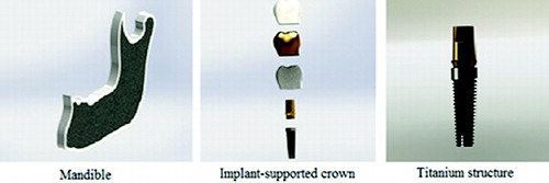
Three-dimensional (3D) finite element models of straight and angled implants with a missing mandibular second molar tooth were created. 3D tetrahedral structural solid models were used to create the bone, implant, framework and occlusal surface materials (). The mandibular bone was modelled as a cancellous core bone surrounded by a 2-mm-thick cortical layer in the upper part. The crowns consisted of framework material and porcelain. The length and diameter of the crown were 8 and 6 mm, respectively. The straight and angled implants were 4.7 × 13-mm screw-type dental implant systems (Zimmer Dental, Carlsbad, CA, USA), and the angled implant had a 30° slope. The frameworks were developed according to the manufacturer's instructions on Y-TZP coping (Nobel-Procera, NobelBiocare AB, Göteborg, Sweden). The design of the frameworks respected the anatomical form of the final restoration: a minimum and a maximum occlusal veneering thickness of 1 and 2 mm, respectively. The frameworks were customized with a minimum thickness of 0.8 mm. Feldspathic porcelain (Ceramco II, Dentsply, Burlington, NJ, USA) was used for the occlusal surfaces.
Figure 1. Mandible, implant-supported crown and titanium structure (abutment + implant body) model.
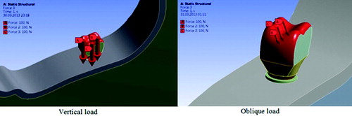
lists the elasticity modules and Poisson ratios of materials used in this study. An average occlusal force of 300 N was used. Total loads at 300 N were applied at the tip of the buccal cusp (100 N), distal fossa (100 N) and mesial fossa (100 N) of the crowns in the vertical direction and in an oblique direction (30° to the vertical) buccolingually ().
Table 1. Poisson ratio and Young's moduli values of materials used in the study.
Figure 2. Examples of vertical and oblique loading forces of 300 N.
The geometry of the teeth models was according to Wheeler.[Citation21] The applied forces were static. Stress levels were calculated using von Mises stress values. Von Mises stresses are appropriate for use with hard materials, such as implants, abutments, frameworks and porcelain.
To perform this study we used an Intel Pentium D CPU 3.00 GHz processor, with a 250 GB hard disk and 3.00 GB of RAM. The computer was equipped with the Windows XP Professional operating system (ver. 2002 with Service Pack 3). Finite element stress analysis and 3D model creation were performed using a laser scanner (NextEngine, Inc., Santa Monica, CA, USA), 3D modelling software (Rhinoceros 4.0, McNeel North America, Seattle, WA, USA) and the stress analysis software (ANSYS Rel.6.0, ANSYS Inc., Houston, TX, USA).
In total, eight models were created. The maximum and minimum von Mises stress values for each were calculated.
Results and discussion
In this study, the finite element stress analysis technique was used to compare stress distributions. The finite element method (FEM) has been demonstrated to be useful in a number of dental studies. The FEM results were presented in terms of the von Mises stress values.[Citation22–24] Since the values that finite element stress analysis gives are in fact variances that occur as a result of non-mathematical calculations, no statistical analysis was conducted. The purpose was, instead, to make a deep analysis of the values and stress distributions.
The maximum and minimum von Mises stress values of the titanium structures (abutment + implant body) and zirconia frameworks of the mandibular straight and angled implant-supported crowns were compared under vertical and oblique occlusal loading forces. Maximum stress values were used for comparisons. In this way, the eight models created were compared with each other according to their maximum and minimum stresses.
The maximum bite force developed by the stomatognathic system in the posterior region is in the range 300–800 N for the first molar teeth.[Citation25,Citation26] In this study, a total force of 300 N was applied at the tip of buccal cusp (100 N), distal fossa (100 N) and mesial fossa (100 N) of the crowns in the vertical direction and in an oblique direction (30° to the vertical) buccolingually.[Citation27,Citation28]
presents the stress distribution within the titanium structure and zirconia framework for the straight implant-supported crown. For both loading forces, maximum stresses were concentrated at the neck of the implant body of the titanium structure; however, minimum stresses were concentrated at the root apex of the implant body part of the titanium structure (). Moreover, while the maximum stress values for the zirconia frameworks were concentrated around the gingival area for both loading forces, minimum stresses were concentrated at the occlusal area of the zirconia frameworks. Maximum stresses were 62.51 MPa for the titanium structure with vertical loading, 244.52 MPa for the titanium structure with oblique loading, 64.02 MPa for the zirconia framework with vertical loading and 229.74 MPa for the zirconia framework with oblique loading ().
Figure 3. Stress analysis of the straight implant-supported crown.
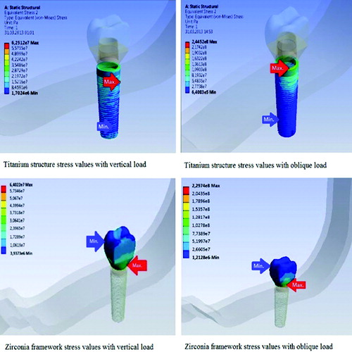
Table 2. Maximum and minimum stress values after force application (MPa).
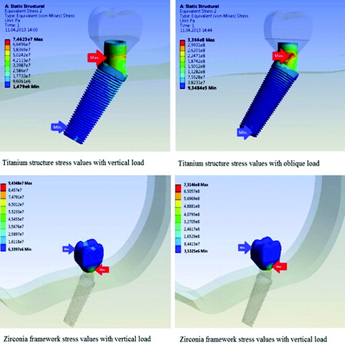
illustrates the stress distribution within the titanium structure and zirconia framework for the angled implant-supported crown. For both oblique and vertical loading forces, maximum stresses were concentrated at the abutment part of the titanium structure; however, minimum stresses were concentrated at the root apex of the implant body part of the titanium structure (). Moreover, the maximum stress values for the zirconia frameworks were concentrated around the gingival area for both loading forces and minimum stresses were concentrated at the occlusal area of the zirconia frameworks. Maximum stresses were 74.62 MPa for the titanium structure with vertical loading, 336.6 MPa for the titanium structure with oblique loading, 94.34 MPa for the zirconia framework with vertical loading and 731.46 MPa for the zirconia framework with oblique loading ().
Figure 4. Stress analysis of the angled implant-supported crown.
Oblique occlusal forces are important to be considered when FEA is applied to dental implants, because the stress results in the structures will be more realistic than those obtained using a vertical occlusal force.[Citation29,Citation30] Papavasiliou et al. [Citation31] showed that oblique loads could increase stresses by up to 10-fold. Similarly, the results of the present study indicated that oblique loading forces caused the highest maximum stress values for both the titanium structures and the zirconia frameworks.
When the two prosthesis-implant systems were examined, the results showed different stress distribution patterns for the two groups. The use of angled implants induced stress concentration in critical points, especially for oblique loads. The highest stress value was concentrated in the zirconia framework of the angled implant-supported model with the oblique loading force (731.46 MPa) (). The lowest stress values were concentrated in the straight implant-supported model (). Similarly, Canay et al.[Citation7] reported a fivefold increase in stress in the platform of an angled implant versus that of a straight implant. Schroeder et al. [Citation32], Sutter et al. [Citation8] and Satoh et al. [Citation33] showed similar results with respect to angled implants. However, Las Casas et al. [Citation1] indicated that stresses in an angled implant were lower than in a straight implant, whereas Cruz et al. [Citation34] and Ferreira [Citation35] showed basically identical stress distribution patterns for both systems.
According to the results obtained in the present study, the stress values with oblique loading forces were higher than with vertical loading forces for both the titanium structures and the zirconia frameworks in both groups. Moreover, the stress values in the angled model were higher than those in the straight model. Furthermore, the zirconia frameworks showed higher stress values than the titanium structures. This could be explained by the fact that zirconia has a higher elastic modulus than titanium. Indeed, Y-TZP has high tensile strength (900–1200 MPa) and a high elastic modulus (210,000 MPa); its elastic modulus being higher than those of all commonly used dental alloys.[Citation36]
Actually, the stress value in the zirconia framework of the angled implant-supported model was considerably higher than expected (731.46 MPa). Since this value is similar to the ultimate strength (900–1200 MPa) of zirconia, the use of a zirconia framework for angled implant-supported crowns is questionable. The zirconia framework used in the present study was also used by Sannino et al. [Citation12], who reported that maximum von Mises stress values were concentrated around the gingival area of the Y-TZP frameworks. Similarly, in our study we found that the maximum stress values were concentrated around the gingival area.
For angled implant-supported models, the von Mises stresses were concentrated at the abutment part of the titanium structure; however, for the straight implant-supported model, stresses were concentrated at the body of the implant. Accordingly, we conclude that loading forces are transmitted through the straight implant better than through the angled implant. Thus, the loading stresses, especially oblique stresses, on angled implant-supported crowns could be harmful to the structure.
Conclusions
Within the limitations of this study, based on the results obtained, it was shown that the stress values were higher in the angled implant-supported crown than in the straight one; and in the model with oblique loading forces than with vertical ones, for both the titanium structures and the zirconia frameworks. Zirconia frameworks showed higher stress values than the titanium structures because of the high elastic modulus of zirconia. The highest stress value was in the zirconia framework of the angled implant-supported model; the value being similar to the ultimate strength of zirconia. Von Mises stresses were concentrated at the abutment part of the titanium structure for the angled implant-supported model; however, for the straight implant-supported model, stresses were concentrated at the body of the implant. Also, the zirconia framework showed the highest maximum stress values around the gingival area. The obtained results could prove useful for clinicians in the field of dental implantology practices.
Acknowledgements
The authors would like to thank Dr Emre Ari (Dicle University, Department of Mechanical Engineering) for his helpful advice on the finite element analysis.
Disclosure statement
The authors deny any conflicts of interest.
References
- Las Casas EB, Ferreira PC, Cimini CAJR, Toledo EM, Barra LP, Cruz M. Comparative 3D finite element stress analysis of straight and angled wedge-shaped implant designs. Int J Oral Maxillofac Implants. 2008;23:215–225.
- Adell R, Lekholm U, Rockler B, Branemark P-I. A 15-year study of osseointegrated implants in the treatment of the edentulous jaw. Int J Oral Surg. 1981;10:387–416.
- Buser D, Mericske-Stern R, Bernard JP, Behneke A, Behneke N, Hirt HP, Belser UC, Lang NP. Long-term evaluation of non-submerged ITI implants. Part 1: 8-year life table analysis of a prospective multi-center study with 2359 implants. Clin Oral Implants Res. 1997;8:161–172.
- Krekmanov L, Kahn M, Rangert B, Lındstrom H. Tilting of posterior mandibular and maxillary implants for improved prosthesis support. Int J Oral Maxillofac Implants. 2000;15:405–414.
- Çağlar A, Aydın C, Ozen J, Yılmaz C, Korkmaz T. Effects of mesiodistal inclination of implants on stress distribution in implant-supported fixed prostheses. Int J Oral Maxillofac Implants. 2006;21:36–44.
- Eger DE, Gunsolley JC, Feldman S. Comparison of angled and standard abutments and their effect on clinical outcomes: a preliminary report. Int J Oral Maxillofac Implants. 2000;15:819–823.
- Canay S, Hersek N, Akpınar I, Asık Z. Comparison of stress distribution around vertical and angled implants with finite-element analysis. Quintessence Int. 1996;27:591–598.
- Sutter F, Schroeder A, Buser DA. The new concept of ITI hollow cylinder and hollow screw implants, 1: engineering and design. Int J Oral Maxillofac Implants. 1988;3:161–172.
- Ten Bruggenkate CM, Oosterbeek HS, Krekeler G, Asikainen PJ. The placement of angled implants in the edentulous maxilla for the use of overdentures. J Prosthet Dent. 1991;66:807–809.
- Rieger MR, Fareed K, Adams WK, Tanquist R. A bone stress distribution for three endosseous implants. J Prosthet Dent. 1989;61:223–228.
- Koca OL, Eskitascioglu G, Usumez A. Three-dimensional finite-element analysis of functional stresses in different bone locations produced by implants placed in the maxillary posterior region of the sinus floor. J Prosthet Dent. 2005;93:38–44.
- Sannino G, Pozzi A, Schiavetti R, Barlattani A. Stress distribution on a three-unit implant-supported zirconia framework. A 3D finite element analysis and fatigue test. Oral Implantol. 2012;5:11–20.
- Raigrodski AJ, Chiche GJ. The safety and efficacy of anterior ceramic fixed partial dentures: a review of the literature. J Prosthet Dent. 2001;86:520–525.
- Mclean JW, Kedge M. The science and art of dental ceramics. In: Preston J, editor. Perspectives in dental ceramics. Chicago (IL): Quintessence; 1988. p. 13–40.
- Sonugelen M, Artuc C. Ağız Protezleri ve Biyomekanik [Oral prostheses and biomechanics]. İzmir: Ege Univ Diş Hek Fak Yayınları; 2002. Turkish.
- Geng J, Yan W, Xu W. Application of the finite element method in ımplant dentistry. Zhejiang: Springer; 2008.
- Beer FP, Johnston ER. Mechanics of materials. New York (NY): McGraw-Hill; 1981.
- Baggi L, Cappeloni I, Girolima MD, Maceri F, Vairo G. The influence of implant diameter and length on stress distribution of osseointegrated implants related to crestal bone geometry. J Prosthet Dent. 2008;100:422–431.
- Sevimay M, Turhan F, Kılıçarslan MA, Eskitaşçıoğlu G. Three dimensional finite element analysis of the effect of different bone quality on stress distribution in an implant-supported crown. J Prosthet Dent. 2005;93:227–234.
- O'Brien WJ, editor. Dental materials and their selection. 3rd ed. Hanover Park (IL): Quintessence Publishing Co., Inc.; 2002.
- Ash MM, Nelson N. Wheeler's dental anatomy, physiology, and occlusion. 8th ed. Philadelphia (PA): Saunders; 2002.
- Magne P, Perakis N, Belser UC, Krejci I. Stress distribution of inlay-anchored adhesive fixed partial dentures: a finite element analysis of the influence of restorative materials and abutment preparation design. J Prosthet Dent. 2002;87:516–527.
- Ona M, Watanabe C, Igarashi Y, Wakabayashi N. Influence of preparation design on failure risks of ceramic inlays: a finite element analysis. J Adhes Dent. 201;13:367–373.
- Belli S, Eskitaşcioglu G, Eraslan O, Senawongse P, Tagami J. Effect of hybrid layer on stress distribution in a premolar tooth restored with composite or ceramic inlay: an FEM study. J Biomed Mater Res B. 2005;74:665–668.
- Bates JF, Stafford GD, Harrison A. Masticatory function – a review of the literature. 1. The form of the masticatory cycle. J Oral Rehabil. 1975;2:281–301.
- Gibbs CH, Mahan PE, Mauderli A, Lundeen HC, Walsh EK. Limits of human bite strength. J Prosthet Dent. 1986;56:226–229.
- Eskitascioglu G, Usumez A, Sevimay M, Soykan E, Unsal E. The influence of occlusal loading location on stresses transferred to implant-supported prostheses and supporting bone: a three-dimensional finite element study. J Prosthet Dent. 2004;91:144–150.
- Tanaka M, Naito T, Yokota M, Kohno M. Finite element analysis of the possible mechanism of cervical lesion formation by occlusal force. J Oral Rehabil. 2003;30:60–67.
- Desai SR, Singh R, Karthikeyan I, Reetika G. Three-dimensional finite element analysis of effect of prosthetic materials and short implant biomechanics on D4 bone under immediate loading. J Dental Implants. 2012;2:2–8.
- Holmgren EP, Seckinger RJ, Kilgren LM, Mante F. Evaluating parameters of osseointegrated dental implants using finite element analysis-a two-dimensional comparative study examining the effects of implant diameter, implant shape, and load direction. J Oral Implantol. 1998;24:80–88.
- Papavasiliou G, Kamposiora P, Bayne SC, Felton DA. Three-dimensional finite element analysis of stress-distribution around single tooth implants as a function of bony support, prosthesis type, and loading during function. J Prosthet Dent. 1996;76:633–640.
- Schroeder A, Sutter F, Krekeler G. Orale Implantologie: Allgemeine Grundlagen Und ITI-Hohlzylindersystem [Oral implantology: general principles and ITI hollow cylinder system]. Stuttgart: Georg Thieme Verlag; 1988. German.
- Satoh T, Maeda Y, Komiyama Y. Biomechanical rationale for intentionally inclined implants in the posterior mandible using 3D finite element analysis. Int J Oral Maxillofac Implants. 2005;20:533–539.
- Cruz M, Wassall T, Toledo EM, Da Silva Barra LP, Cruz S. Finite element stress analysis of dental prostheses supported by straight and angled implants. Int J Oral Maxillofac Implants. 2009;24:391–403.
- Ferreira PC. Modeling of the biomechanical behaviour of an edentulous mandible with vertical and angled implants [dissertation]. Belo Horizonte: Federal University of Minas Gerais; 2003.
- Piconi C, Maccauro G. Zirconia as a ceramic biomaterial. Biomaterials. 1999;20:1–25.