
 ?Mathematical formulae have been encoded as MathML and are displayed in this HTML version using MathJax in order to improve their display. Uncheck the box to turn MathJax off. This feature requires Javascript. Click on a formula to zoom.
ABSTRACT
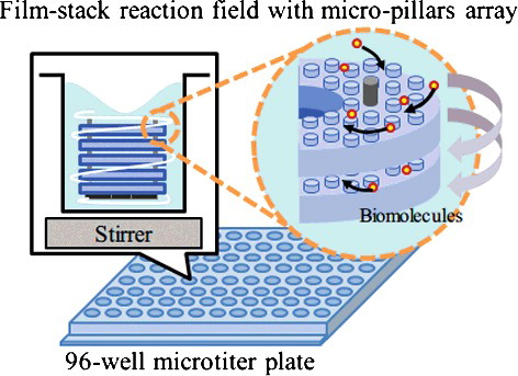
For high sensitivity and rapid reaction of enzyme-linked immunosorbent assay (ELISA), the film-stack reaction field with micro-pillars array was designed and developed. The film-stack reaction field was fabricated by a nanoimprint process and an automatic punch-press process. The films with different gaps between micro-pillars (5, 10 and 50 μm) were prepared. These reaction fields were evaluated by IgA ELISA using 96-well microtitre plates and the computational simulation analysis of the fluid flow and the particle trajectory. Compared with ELISA using only the microtitre plate, higher detection sensitivity and shorter incubation time were achieved using the film-stack reaction field due to the increased surface area and the circulating flow through the space between films in a well by the rotation of the film-stack reaction field. Furthermore, in the ELISA results obtained using the film-stack reaction fields, the fluorescence intensities in 10-μm and 50-μm pillar gaps were the minimum and maximum values, respectively. This trend was due to the flow rate between micro-pillars, and the number and the diffusion distance of supplied biomolecules to the inertial space in the film-stack reaction field. In simulation results, the trend of the number of adsorbed biomolecule particles with different gaps between micro-pillars was in agreement with the trend in the ELISA results. Hence, these simulation analyses were validated in the quantitative evaluation of this reaction field and could be applied in the design of this reaction field as an effective design tool.
Introduction
Immunoassays, such as enzyme-linked immunosorbent assay (ELISA), are very important methods for the detection of various proteins in immunologic reactions with an application in numerous disciplines including the diagnosis of infectious diseases [Citation1–6]. ELISAs are basically carried out in 96-well microtitre plates, which provide advantages such as high specificity, sensitivity and ability to perform multiple assays in a parallel way [Citation1–4]. Nonetheless, it takes a long time to complete the assay due to the large diffusion distance, the requirement of large volumes of reagents, and the lack of portability [Citation2–9]. Recently, with the development of the microfabrication techniques, micro bio-analysis devices (MBDs), such as micro-total analysis systems and lab-on-a-chip, are demanded to achieve rapid detection of biomolecules [Citation10–12]. This is due to the short diffusion distance of biomolecules and the high surface-to-volume ratio by miniaturizing a reaction field. However, a whole system with MBDs becomes complicated by using dedicated devices such as a supply pump and a specialized detection system. Furthermore, for the fabrication techniques of MBDs, there are two approaches: a top-down process and a bottom-up process. The top-down process reduces a large piece of material to produce the form with a desired shape and size of micrometer scale. However, it has multiple steps which induce high cost for mass production. On the other hand, the bottom-up process easily builds up the form with nanometer scale from nano-components (for example, atom, molecular and nano-materials) by self-assembly, but it is difficult to control the desired shape and size [Citation13,Citation14]. Therefore, the novel fabrication technique of MBDs is required for high quality and mass production at a low cost. Moreover, many researchers have developed different kinds of reaction fields in MBDs by trial and error, but an optimized design of the reaction field for high sensitivity and rapid reaction has not been achieved. The design parameters, such as the size, shape, surface area and surface properties of the reaction field, are important factors because these parameters relate to the physical phenomena (e.g. the convection of buffer solution, the diffusion of biomolecules, and the surface interaction between a reaction field and a biomolecule) [Citation15–18]. These phenomena influence the transport, adsorption and reaction of target biomolecules [Citation19,Citation20]. Therefore, a design tool with consideration of the physical phenomena is required in the optimized design of a reaction field for high sensitivity and rapid reaction.
Singh et al. [Citation21] have suggested the film-stack reaction field with micro-pillars array for the ELISA device as shown in . This device is composed of several films with a micro-pillars array and a magnetic sheet at the bottom of the device. This achieves high detection sensitivity due to the large surface area and rapid reaction due to the device rotation by a magnetic stirrer in an ELISA process. This reaction field is placed in a well of a 96-well microtitre plate and the measurements are performed with a conventional ELISA microplate reader. Moreover, the fabrication process of this device includes the nanoimprint process for the fabrication of micro-pillars array on a film and the punch-press process for the shaping and stacking of circular film automatically. Therefore, this process is expected to give high quality and low-cost mass production. On the other hand, ELISA tests using reaction fields of different shapes and dimensions of micro-pillars have been performed but an optimized design, however, has not been reported.
Figure 1. Schematic image of a film-stack reaction field with a micro-pillars array in a well of a 96-well microtitre plate.
The focus of this paper is on the structural dimensions of a micro-pillars array on a film as the design parameter with the aim to investigate the influence of the micro-pillars dimension on the detection sensitivity and reaction time by ELISA experiment and computational analysis. The computational analysis as a design tool is expected to optimize the design of the reaction field for high sensitivity and rapid reaction. The computational analysis was based on the fluid-flow analysis based on finite elements method (FEM) and the particle trajectory analysis based on the Newtonian equation of movement using the fluid-flow analysis for the biomolecules transport. These analyses clarified the effects of the structural dimension of the micro-pillars array on the flow vectors and the number of adsorbed biomolecules in this device.
Materials and methods
Experiments
Fabrication of the film-stack reaction field with micro-pillars array
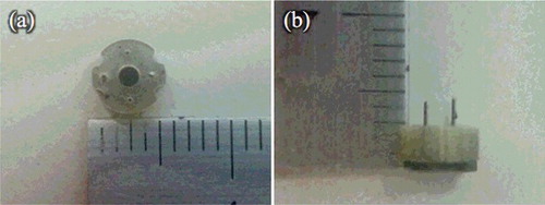
shows the appearance view of the film-stack reaction field. A polyethylene terephthalate (PET) sheet was used as the base film. Acrylic resin was coated on this film and hexagonal-patterned micro-pillars were moulded by a nanoimprint process. Then, five films with micro-pillars array were automatically punched and stacked by a press machine. The outside diameter and the central-hole diameter of the punched film are 5.0 mm and 2.0 mm, respectively. Five punched films were fixed by two metal pins. Moreover, a magnetic sheet which was punched in the form of a cross shape was fixed at the bottom of the film-stack reaction field in order to rotate this reaction field in a well by a magnetic stirrer during the ELISA procedure.
Figure 2. Optical images of the film-stack reaction field with a micro-pillars array: top view (a); side view (b). The outside diameter and the central-hole diameter were 5.0 and 2.0 mm, respectively. The height from a top film to a bottom magnetic sheet is approximately 3.0 mm. The space between the films is 10 μm, which depends on the height of a micro-pillar.
The different dimensions of the micro-pillars array were prepared to design a highly effective reaction field. gives the structural dimensions of the micro-pillars array. shows scanning electron microscope (SEM) images of micro-pillars array of different dimensions.
Table 1. Structural dimensions of the micro-pillars array.
Figure 3. SEM images of micro-pillars array on the film. The diameters and heights of the micro-pillars are 50 and 10 μm, respectively. The gaps between the micro-pillars are 5 μm (a), 10 μm (b) and 50 μm (c).
IgA ELISA
IgA ELISA was carried out using wells with or without film-stack reaction fields with different dimensions of a micro-pillars array at room temperature. For the incubation of Human IgA (Bethyl Laboratories, Inc., USA) on the surfaces of wells and the film-stack reaction fields, 100 μL of 10% purified Human IgA diluted in 0.1 mol/L carbonate buffer solution (CBS, pH = 9.5) was added to each well. In the wells with the film-stack reaction fields, these reaction fields were rotated by a magnetic stirrer for 1 min and left for 59 min. The well without the reaction field was left for 1 h. After the incubation, the human IgA solution was removed from each well and each well was washed with 300 μL of Tris buffer saline (TBS, pH = 8.0) containing 0.05% Tween-20 (TBS-T). Then, blocking was performed using 200 μL of TBS containing bovine serum albumin (TBS-BSA; EMD Millipore Corp., USA) for 30 min. In the case of the wells with the film-stack reaction fields, these reaction fields were rotated by a magnetic stirrer for 1 min and left for 29 min. After the blocking, the TBS-BSA solution was removed from each well and each well was washed with 300 μL of TBS-T. Furthermore, for the incubation of horseradish peroxidase conjugated goat Human IgA antibody (HRP-IgA, Bethyl Laboratories, Inc., USA) in each well, 100 μL of 0.01% HRP-IgA diluted in TBS-BSA was added to each well. This step was performed in two incubation times of 5 and 15 min to evaluate the duration of HRP-IgA incubation in each well. The reaction fields were kept rotating during HRP-IgA incubation. After the incubation, the HRP-IgA solution was removed from each well and each well was washed by 300 μL of TBS-T. Finally, 100 μL of 1% Amplex® Red (Thermo Fisher Scientific Inc., USA) solution diluted in 50 mmol/L phosphate buffer saline (PBS, pH = 7.4) and hydrogen peroxide solution was added to each well. Then, the plates were developed in a dark place for 15 min, where the reaction fields were kept rotating. After Amplex® Red stop reagent (Thermo Fisher Scientific Inc., USA) was added to each well, 80 μL of the reaction solution was moved to another well in order to keep the height of the solution level in all wells. The fluorescence intensity in each well was measured by a plate reader (Spectra Fluoar, TECAN, Switzerland). The rotating speed of the film-stack reaction field was 2500 rpm in each step.
Computational analysis
Geometry model
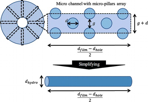
In this work, three geometry models were employed, as shown in . The first model is a whole well with a film-stack reaction field, which is with no micro-pillars array and two-dimensional axisymmetric due to the simple axisymmetric geometry ((a)). In this model the fluid flow in a well with rotating a film-stack reaction field was analyzed. To verify the fluid flow in different gaps between micro-pillars, the micro-channel with micro-pillars on a film was modelled as two-dimensional geometry in the second model ((b)). The third model is a two-dimensional circular tube with hydrodynamic diameter which is calculated using the diameter and the gap of the micro-pillars array ((c)). The hydrodynamic diameter is expressed by(1)
(1)
Figure 4. Geometry models in the fluid-flow analysis and the particle trajectory analysis. A whole well (a) with a film-stack reaction field; a micro-channel (b) with different dimensions of micro-pillars array on a film; a circular tube (c) with hydrodynamic diameter dhydro. dfilm and dhole are the outside diameter and the central-hole diameter of a film, respectively; dhydro is calculated using the diameter and the gap of the micro-pillars array.
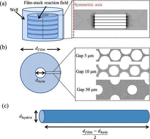
In the equation, dhydro is the hydrodynamic diameter, g is the gap between micro-pillars, and h is the height of a micro-pillar. This model is the simplified model of a micro-channel with micro-pillars array (see ) and was used in the particle trajectory analysis. A circular-tube model has been employed in many studies investigating the particle trajectory for microfluidic devices and bio-applications. Adamczyk and Van De Ven [Citation22] investigated the particle transport and deposition in a circular channel. Waghmare and Mitra [Citation23] studied the transport of biomolecules and cells through buffer solution in micro-channels for immunoassay-based sensing devices. Chatterjee et al. [Citation24] theoretically verified the particle transport in a circular micro-channel whose surface is electrically patterned. The flow distribution in a circular-tube channel, as shown in many reports, is based on the Hagen–Poiseuille law. Therefore, the simulation conditions of a circular tube in these studies were applied to this work. In the analysis of fluid-flow analysis and the particle trajectory, COMSOL Multiphysics® (COMCOL, Inc., USA) was employed as the simulation software based on the FEM.
Figure 5. Conceptual image of the micro-channel model and the circular-tube model. The space between films is assumed to be composed of multiple micro-channels. The number of micro-channels depends on the structural dimensions of the micro-pillars array. A circular tube with hydrodynamic diameter is the simplified model of a micro-channel with a micro-pillars array.
Governing equation and boundary conditions of the fluid-flow analysis
The buffer solution is assumed to flow in a well, or through a micro-channel and a circular tube at steady state. A two-dimensional incompressible Navier–Stokes equation was used along with the continuity equation to find the fluid velocity profile throughout the domain.(2)
(2)
In this equation, u is the flow velocity vector, p is the pressure, ρ is the density and μ is the viscosity. The density and the viscosity are assumed to be the same as those of water. In the first model, which is a whole well with a film-stack reaction field, the moving boundary condition is assumed to be at the film walls. The movement velocity is assumed to be the rotation velocity of the film-stack reaction field around the symmetrical axis. Therefore, the movement velocity is given by(3)
(3)
Here, vφ is the movement velocity around the symmetric axis, r is the circumferential distance in the first model and ω is the angular velocity. The angular velocity equals 2πnrpm (nrpm is the rotation number of a film-stack reaction field).
In the second model, the no-slip boundary condition is assumed at the micro-pillar walls. The symmetric boundary condition is assumed at the channel walls. A constant velocity is specified at the inlet. This velocity is the average velocity at the space between films calculated in the first model. The outlet is assumed to be at zero pressure.
In the third model, the no-slip boundary condition is assumed at the walls. A constant velocity is specified at the inlet. This velocity is the average velocity between micro-pillars calculated in the second model. The outlet is assumed to be at zero pressure.
The conditions of the fluid-flow analyses in all models are shown in .
Table 2. Conditions used in the fluid-flow analysis in all models.
Particle trajectory analysis
To analyze the biomolecules transport with different dimensions of the micro-pillars array, particle trajectory analysis was carried out using the third model. Biomolecules are assumed to be transported by the acting force such as gravity force, buoyancy force, drag force and Brownian force. The governing equation with this assumption is denoted by the Newtonian equation of motion:(4)
(4)
In this equation, mp is the mass of a biomolecule particle and vp is the particle velocity vector.
Fmass is a gravity and buoyancy force, and is given by(5)
(5) where ga is the gravitational acceleration vector, ρp is the particle density and ρ is the density of the buffer solution
FD is the drag force induced by the buffer flow.(6)
(6) in which μ is the viscosity of the buffer solution, rp is the particle radius, and u is the velocity of the buffer solution calculated in the fluid-flow analysis in the third model.
FB is the Brownian force modelled as a Gaussian white noise process [Citation25–27].(7)
(7)
In this equation, ξ is a Gaussian random number with zero mean and unit variance, kB is Boltzmann constant, T is the absolute temperature, Δt is the magnitude of the time step.
As the boundary conditions of the particle trajectory analysis, biomolecule particles are assumed to be supplied from the tube inlet with a different number of particles in each dimension of the micro-pillars array. The space between the films is assumed to be composed of multiple micro-channels and a circular tube is the simplified model of a micro-channel with the micro-pillars array, as shown in . The number of circular tubes is given by(8)
(8) where Ntube is the number of circular tubes, dhole is the central-hole diameter of a film-stack reaction field and d is the diameter of a micro-pillar. Therefore, the number of supplied biomolecule particles to a circular tube is expressed by
(9)
(9)
Here, nb is the number of supplied biomolecule particles to a circular tube and ntotal is the total number of biomolecules in a well. On the other hand, biomolecule particles are assumed to be ejected to the tube outlet and adsorbed onto the tube walls. In this analysis, the number of adsorbed biomolecule particles on the walls was evaluated by comparison with different dimensions of the micro-pillars array in a film-stack reaction field, which is almost proportional to the fluorescence intensity in IgA ELISA. The conditions of the particle analysis are presented in .
Table 3. Conditions used in the particle trajectory analysis.
Results and discussion
The fluorescence intensity in IgA ELISA
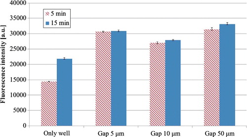
The fluorescence intensities at two durations of incubation time for HRP-IgA in wells with or without film-stack reaction fields with different dimensions of micro-pillars array are presented in . The results showed that the average intensity of all wells with film-stack reaction fields was 2.0-fold and 1.4-fold higher than that in wells without film-stack reaction fields at the incubation times of 5 and 15 min, respectively. This is due to the increase of the surface area of reactions by using the film-stack reaction fields. The surface area of a well only is 93 mm2, whereas the average surface area of all wells with film-stack reaction fields is 287 mm2, which is 209% higher compared to that of the wells without film-stack reaction fields. Furthermore, the average intensity at 5 min compared to the one at 15 min was 3% lower in all wells with film-stack reaction fields and 34% lower in the wells without film-stack reaction fields. This indicated that the HRP-IgA reaction on the surface in a well became more rapid and almost saturated using a film-stack reaction field. On the other hand, the surface area of the wells with the film-stack reaction fields with different dimensions of micro-pillars array is 301 mm2 in the case of 5-μm gaps, 293 mm2 in the case of 10-μm gaps and 267 mm2 in the case of 50-μm gaps. Thus, it might be expected that the fluorescence intensity would be highest with the 5-μm gaps and that the relationship between the intensity and the gap size of the micro-pillars array would be linear. However, the maximum intensity was actually that achieved with the 50-μm gaps, and the lowest one with the 10-μm gaps. In the reaction field with the buffer flow, not only the surface area of the reaction field, but also the convection flow and the diffusion distance of biomolecules affect the number of adsorbed or reacting biomolecules, which is closely related to the detection sensitivity [Citation8,Citation27]. In the case of the film-stack reaction field, the surface area was increased by the number of stacked films and micro-pillars array. On the other hand, the flow velocity and diffusion distance of biomolecules depend on the rotation speed of this reaction field and the structural dimensions of the micro-pillars array. Therefore, these parameters should be considered for high sensitivity and rapid reaction. In the fluorescence intensities at 5 min, the difference between the intensities achieved with gaps of 5 and 50 μm was small and the intensity measured with the gaps of 10 μm was lowest. Moreover, the difference between the intensities at 5 and 15 min in the case of 5-μm gaps was smaller than that in the case of 50-μm gaps. These results might indicate that the fluorescence intensity in the reaction fields with 5-μm gaps became saturated at 5 min and the gradient of the intensity in the fields with 50-μm gaps from 0 s to the time constant is equal to or less than the one in the fields with 5-μm gaps. Therefore, the influence of the other incubation times besides 5 and 15 min on the fluorescence intensities measured with each gap size needs to be verified. As a next step in our study, the influence of the detection sensitivity and the incubation time on these parameters was verified by the analyses of the fluid flow and the particle trajectory.
Figure 6. Fluorescence intensities at two incubation times for HRP-IgA in wells with or without film-stack reaction fields with different dimensions of micro-pillars array (N = 3).
Fluid-flow and particle trajectory analysis
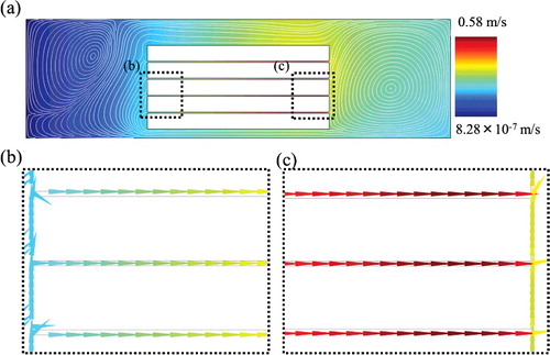
IgA ELISA indicated higher sensitivity and more rapid reaction with all film-stack reaction fields compared with wells only. According to the fluid-flow analysis in the first model of a whole well with a film-stack reaction field (), the circulating flow through the space between films in a well is induced by the rotation of a film-stack reaction field using a magnetic stirrer. This flow is expected to promote the rapid supply of biomolecules to the surface in a well. Therefore, this result shows that the convection flow in a well and the number of films provide high detection sensitivity and short incubation time in IgA ELISA using the film-stack reaction field.
Figure 7. Flow velocity and streamline at the fluidic analysis in the first model of a whole well with a film-stack reaction field: a whole geometry (a); enlarged images (b) and (c), which show the flow velocity vectors. The flow direction is from the central-hole to the outside of a film-stack reaction field. The average velocity between films is 0.43 m/s.
On the other hand, the trend of the fluorescence intensity in film-stack reaction fields with different dimensions was not linear with respect to the gap size between micro-pillars. Hence, the influence of different dimensions of micro-pillars array on the fluorescence intensity was investigated by the analysis of the fluid flow and the particle trajectory in the second and third models, which are the micro-channel with micro-pillars array and the circular tube with the hydrodynamic diameter, respectively.
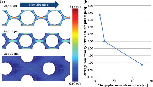
(a) shows the fluid velocity and streamline of micro-channels with different dimensions of micro-pillars array using the second model. The inlet velocity of all channels was 0.43 m/s, which is the average velocity between films calculated by the first model as shown in . In the 5- and 10-μm gaps, the high velocity was distributed between the micro-pillars, whereas the distribution of the flow velocity was relatively uniform in the 50-μm gaps. The average velocities between micro-pillars were 4.35 m/s in the 5-μm gaps, 2.50 m/s in the 10-μm gaps and 0.86 m/s in the 50-μm gaps as shown in (b). The high velocity induces a high shear rate, which prevents the adsorption of biomolecules on a surface [Citation28]. Using these average velocities as the inlet velocities of the third model, the fluid flow and the particle trajectory analyses were performed.
Figure 8. Fluid velocity and streamline of micro-channels with different dimensions of micro-pillars array using the second model (a); average flow velocity between micro-pillars with different dimensions (b). The inlet velocity of all channels is 0.43 m/s, which is the average velocity between films calculated by the first model as shown in .
presents the number of adsorbed biomolecule particles on the wall of a circular tube in the third model. Although the 5-μm gaps provide the shortest diffusion distance of biomolecule particles in all gaps, the number of adsorbed biomolecule particles in the 50-μm gaps was highest in all tubes. In the 50-μm gaps, a higher number of biomolecule particles were supplied to the tube compared with the other gap sizes. Moreover, the rapid fluid velocity in the 5-μm gaps may prevent the adsorption of biomolecule particles. Furthermore, it is considered that the minimum number of adsorbed biomolecule particles in the 10-μm gap is due to both the low number of supplied particles and the high flow velocity in the tube. On the other hand, to evaluate the number of adsorbed biomolecule particles in the space between films, the total number of adsorbed biomolecule particles in all circular tubes was calculated by multiplying the number in a circular tube by the number of circular tubes per space between films (see Equation Equation8(8)
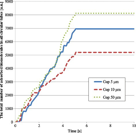
(8) ), as shown in . The trend of this number was almost the same as that of the fluorescence intensity in , which validated these analyses of the fluid flow and the particle trajectory in the quantitative evaluation of a film-stack reaction field. Furthermore, the ratio of the number of adsorbed biomolecules in the 5-μm gaps to the one in the 50-μm gaps increased compared with the case of the circular tube in . This is due to the number of circular tubes, which are 114 in the case of 5-μm gaps, 105 in case of 10-μm gaps and 63 in the case of 50 μm gaps. The number of circular tubes is proportional to the surface area of a film-stack reaction field. Therefore, the results from these analyses showed that the detection sensitivity and the incubation time are particularly related to the surface area, the structural dimensions, the flow velocity and the number and the diffusion distance of the supplied biomolecules to the inertial space in the film-stack reaction field. Moreover, these analyses can be applied on the design of this reaction field as an effective design tool. Hence, considering the above factors, the optimized design of the film-stack reaction field with the analyses of the fluid flow and the particle trajectory can be expected to produce a reaction field with high sensitivity and rapid reaction.
Figure 9. Number of adsorbed biomolecule particles in a circular tube with hydrodynamic diameter by particle trajectory analysis in the third model.
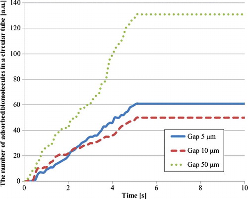
Figure 10. Total number of adsorbed biomolecule particles in all circular tubes. This number was calculated by multiplying the number of adsorbed biomolecule particles in a circular tube by the number of circular tubes per space between films as shown in EquationEquation (8(8)
(8) ). There are 114 circular tubes in the 5-μm gap, 105 ones in the 10-μm gap and 63 ones in the 50-μm gap.
Conclusions
The film-stack reaction field with different dimensions of a micro-pillars array was verified for its optimization to high sensitivity and rapid ELISA reaction in this work. These reaction fields were characterized by IgA ELISA, the fluid-flow analysis based on FEM and the particle trajectory analysis using the fluid-flow analysis. The film-stack reaction field was fabricated by a nanoimprint process and automatic punch-press process. The results from the fluid-flow analysis indicated that, compared with IgA ELISA using only a 96-well microtitre plate, higher detection sensitivity and shorter incubation time were achieved using the film-stack reaction field due to the increase in the surface area and the circulating flow through the space between films in a well by the rotation of the film-stack reaction field using a magnetic stirrer. Furthermore, in the ELISA results using the film-stack reaction fields, the fluorescence intensity in the fields with 10-μm pillar gaps was the local minimum value and the one in the fields with 50-μm pillar gaps was the maximum value. The simulation analyses showed that this trend of the fluorescence intensity with different gaps between micro-pillars was brought about by the flow rate between micro-pillars and the number and diffusion distance of biomolecules supplied to the inertial space in the film-stack reaction field. Moreover, the trend in the number of adsorbed biomolecule particles with different gaps between micro-pillars was similar to the trend in the ELISA results in the particle trajectory analysis. Hence, these simulation analyses could be considered validated in the quantitative evaluation of a film-stack reaction field, and can be applied on the design of this reaction field as an effective design tool. The optimized design of the film-stack reaction field using the analyses of the fluid flow and the particle trajectory can be expected to produce a reaction field with high sensitivity and rapid reaction. The developed film-stack reaction field is expected to be applied on various ELISAs and other diagnosis devices by the verification of the wider efficiency in this reaction field.
Disclosure statement
No potential conflict of interest was reported by the authors.
Additional information
Funding
References
- Engvall E. The ELISA, enzyme-linked immunosorbent assay. Clin Chem. 2010;56(2):319–320.
- Sun S, Yang M, Kostov Y, et al. ELISA-LOC: lab-on-a-chip for enzyme-linked immunodetection. Lab Chip. 2010;16:2093–2100.
- Chin CD, Laksanasopin T, Cheung YK, et al. Microfluidics-based diagnostics of infectious diseases in the developing world. Nat Med. 2011;17:1015–1019.
- Zheng C, WAng J, Yuhong Pang, et al. High-throughput immunoassay through in-channel microfluidic paitterning. Lab Chip. 2012;12(14):2487–2490.
- Lequin RM. Enzyme Immunoassay (EIA)/Enzyme-Linked Immunosorbent Assay (ELISA). Clin Chem. 2005;51:2415–2418.
- Voller A, Bartlett A, Bidwell DE. Enzyme immunoassays with special reference to ELISA techniques. J Clin Pathol. 1978;31(6):507–520.
- Mendoza LG, McQuary P, Mongan A, et al. High-throughput microarray-based Enzyme-Linked Immunosorbent Assay (ELISA). BioTechniques. 1999;27:778–788.
- Xue S, Zeng H, Yang J, et al. A compact immunoassay platform based on a multicapillary glass plate. Sensors. 2014;14(5):9132–9144.
- Inoue Y, Nishiwaki M, Kudo Y, et al. Preparation of two-dimensionally ordered microbeads structure dispensed with an ink-jet and its application to ELISA. Anal Sci. 2009;25(2):325–239.
- Geschke O, Klank H, Telleman P. Microsystem engineering of lab-on-a-chip devices. Weinheim: Wiley -VCH; 2004. p. 13–36.
- Manz A, Graber N, Widmer HM. Miniaturized total chemical analysis systems: a novel concept for chemical sensing. Sens Actuators B Chem. 1990;1(1–6):244–248.
- Voldman J, Gray ML, Schmidt MA. Microfabrication in biology and medicine. Annu Rev Biomed Eng. 1999;1:401–425.
- Moronuki N. [Surface functions brought by surface micro structures]. Tokyo: Morikita; 2011. Japanese.
- Suzuki Y, Pabjańczyk-Wlazło E, Onoda J, et al. Fabrication and evaluation of micro-structured reaction field with vertically aligned carbon nanotubes for micro bio-analysis device. Mech Eng J. 2016;3(2), 15–00567. [ 9 p].
- Parsa H, Chin CD, Mongkolwisetwara P, et al. Effect of volume- and time-based constraints on capture of analytes in microfluidic heterogeneous immunoassays. Lab Chip. 2008;8(12):2062–2070.
- Wild D. The immunoassay handbook. Amsterdam: Elsevier Science; 2005. p. 175–202.
- Rossier JS, Gokulranga G, Girault HH, et al. Characterization of protein adsorption and immunosorption kinetics in photoablated polymer microchannels. Langmuir. 2000;16:8489–8494.
- Goldstein B, Coombs D, He X, et al. The influence of transport on the kinetics of binding to surface receptors: application to cells and BIAcore. J Mol Recognit. 1999;12(5):293–299.
- Jomeh S, Hoorfar M. Numerical modeling of mass transport in microfluidic biomolecule-capturing devices equipped with reactive surfaces. Chem Eng J. 2010;165(5):668–677.
- Jomeh S, Hoorfar M. Study of the effect of electric field and electroneutrality on transport of biomolecules in microreactors. Microfluid Nanofluid. 2012;12(1):279–294.
- Singh H, Morita T, Suzuki Y, et al. High sensitivity, high surface area Enzyme-linked Immunosorbent Assay (ELISA). Biomed Mater Eng. 2015;26(3–4):115–127.
- Adamczyk Z, Van De Ven TGM. Deposition of particles under external forces in laminar flow through parallel-plate and cylindrical channels. J Colloid Interface Sci. 1981;80(2):340–356.
- Waghmare PR, Mitra SK. Mechanism of cell transport in a microchannel with binding between cell surface and immobilized biomolecules. ASME 2009 international mechanical engineering congress and exposition. Proceedings; 2009 Nov 13–19; Lake Buena Vista, FL. ASME; 2010. New York: ASME; 2009. p. 779–784.
- Chatterjee R, Bhattacharjee S, Mitra SK. Particle transport in patterned cylindrical microchannels. Microfluid Nanofluid. 2012;12(1):41–51.
- Amy L, Ahmadi G. Dispersion and deposition of spherical, particles from point sources in a turbulent channel flow. Aerosol Sci Technol. 1992;16(4):209–226.
- Myung-m K, Zydney AL. Effect of electrostatic, hydrodynamic, and Brownian forces on particle trajectories and sieving in normal flow filtration. J Colloid Interface Sci. 2004;269(2):425–431.
- Liu Y, Zhang Y, Lu Z, et al. 3-D microarray and its microfabrication-free fluidic immunoassay device. Anal Chim Acta. 2015;889:187–193.
- Kim J, Ryu G, Shin I, et al. Effect of shear rates on protein adsorption in the total artificial heart. ASAIO J. 1992;38(3):M532–M535.