
 ?Mathematical formulae have been encoded as MathML and are displayed in this HTML version using MathJax in order to improve their display. Uncheck the box to turn MathJax off. This feature requires Javascript. Click on a formula to zoom.
ABSTRACT
There is an increase in the incidence of hip fractures worldwide in recent years, associated with the upward trend in the life expectancy of the human population. Hip fractures occur mostly in patients aged over 60 years. Therefore, the task for optimization of hip fracture treatment and maximal patients’ recovery is of serious social importance. Many scientists devote their efforts to improving the solutions to such cases. This work presents a specific algorithm developed for registration of human femoral head far cortex and human femoral head end. Its realization is a very successful robot application in the orthopaedic surgery – automatic bone drilling. The experimental specimens are human hip heads obtained during hip-joint excision arthroplasty. The device indicates the maximal hole depths which could be reached. Such information helps to determine and calculate the accurate implant size to ensure its positioning in the desired area of the hip head and reaching maximal fixation strength. The risk of penetration into the joint capsule is eliminated by software defence that the robot is responsible for. The proposed solution is a promising approach towards improvement of the precision and outcome of hip fracture treatment.
Introduction
There has recently been a growing interest in robots for specific orthopaedic manipulations, aiming at greater accuracy and safety, reduced invasiveness, shorter intervention time and faster patient recovery [Citation1–3]. The most prominent orthopaedic robots are RoboDoc (Integrated Surgical Systems, Sacramento, CA), Acrobot (Imperial College London), MARS (MiniAture Robot for Surgery, Masor Robotics Ltd), CRIGOS (Compact Robot for Image Guided Orthopaedic Surgery), CASPAR (Computer Assisted Surgical Planning and Robotics system, OrtoMaquet), RIO robotic arm (MAKO Surgical Corp.), iBlock (Praxim Inc., an Orthopaedic Synergy Inc. company) and Navio PFS (Blue Belt Technologies) [Citation4]. These robotized systems, however, are very expensive, complicated and require special maintenance [Citation3].
The new research directions in surgical robotics are focused on the development of small, special-purpose and cost-effective robotized surgical devices that will be easy to use and more convenient in the confined operative field [Citation1,Citation3]. Several studies refer to the development of miniature robots like MARS or hand-held robots [Citation5]. Such devices would greatly facilitate the cutting and bone drilling manipulations in orthopaedic surgery, viz. total knee arthroplasty (TKA) and total hip arthroplasty (THA) as well as bone fractures [Citation1,Citation3].
The hip-fracture is generally a break in the upper part of the femur bone. It occurs mostly in patients aged over 60 years. Worldwide, there is a clear upward trend in the life expectancy of the human population. It is expected for the number of individuals aged 65 years and older to increase from the current 323 million to 1555 million by the year 2050. These demographic changes can be expected to cause an increase in the number of hip fractures from 1.66 million in 1990 to 1996 and 26 million in 2050 [Citation6]. Moreover, hip fractures are proven as one of the main reasons for mortality of the elderly. For example, the mortality by the end of the first year after the trauma reaches 27.3% depending on the kind of hip fracture and the type of treatment [Citation7]. These data underline the social importance of the problem and a lot of researchers have devoted their efforts to optimization of hip fracture treatment and maximal recovery of patients.
Classification and treatment of hip fractures
The classification of hip fractures is the basis for their right diagnosis and treatment. Hip fractures are classified into different subgroups depending on the anatomical localization and fracture complexity [Citation8,Citation9]. There are two main categories, the intracapsular (femoral neck) fractures and the extracapsular (trochanteric and subtrochanteric) fractures.
Trochanteric and subtrochanteric fractures [Citation9] are usually treated with a sliding hip screw (SHS) or an intramedullary nail (IMN). Both techniques as well as the fixation of the intracapsular fractures require the hole to be realized through the lateral femur cortex in the trochanteric area. Such a hole must pass through the neck and must reach as close as possible to the end of the femoral head [Citation8].
Implant positioning
For metal osteosynthesis of fractures of the proximal hip, the implant goes through the side hip cortex and anchors in the hip neck and hip head. Stable fixation is achieved when the implant is incorporated into the hip head. The screw should be placed through the crossing area of the principal tensile group with other groups. The neck has the highest density in this area, so the screw can reach a maximum depth without capsule penetration [Citation10]. The trabecular structure pattern of proximal femur [Citation11] is shown in .
Figure 1. Trabecular structure of proximal femur [Citation11].
![Figure 1. Trabecular structure of proximal femur [Citation11].](/cms/asset/70950513-634f-4878-9b13-8d853fd313cd/tbeq_a_1407256_f0001_oc.jpg)
Ward's Triangle is the area of the femoral neck formed by the intersection of three bundles of trabeculae: principal (primary) compressive trabeculae medially, principal (primary) tensile and secondary compressive trabeculae laterally. It is an area of low bone density. In older patients, diminution of the trabeculae leads to enlargement and indistinctness of this region between the load-bearing trabecular patterns. In the case of osteopenia (T-score ranging from −1 to −2.5) and especially of osteoporosis (T-score of less than −2.5), this effect additionally enlarges the zone with lower bone density.
In order to unify the implant tip positioning, the hip head is divided into nine zones [Citation12] according to the superior, inferior, anterior and posterior part of the head. Most authors favour the central (centre–centre) position or an inferior position for placement of the screw into the hip head. There is nearly unanimous agreement that the anterior–superior location must be avoided.
Postoperative complications
The postoperative complications related to fracture treatment by osteosynthesis mostly appear as femoral head cut-out, implant penetration into the capsule or difficult recovery of the fracture due to fixation destruction. All this requires reoperation and changing the implant or arthroplasty. The postoperative complications are also a result of various factors, such as poor reduction, low bone density (osteoporosis), unstable fracture, valgus angle etc. However, the main reason for these complications is wrong positioning of the implant screws into the femoral neck-head fragment of the proximal femur. As an implant-positioning criterion, the TAD-index (Tip-to-Apex Distance) [Citation12] is used. The optimal positioning corresponds to TAD-index minimization. For example, for the cut-out probability, the most reliable prognosis factor is the TAD-index. If the TAD-index is less than 24 mm, such cut-out cases are not registered [Citation12].
Aim of the present research
The aim of this work was to achieve a maximally accurate depth of the hole. This is done by registration of the human femoral head far cortex or hip head end by applying automatic drilling. The result would be optimal implant positioning into the hip head and elimination of the risk of capsule penetration.
Subjects and methods
Specimens
The experimental specimens were human hip heads obtained during hip joint excision arthroplasty of patients – women and men – aged between 41 and 89 years. The need for operative intervention was hip neck fracture or osteoartrosis where the hip head had to be cut out. The hip head was cut by instruments which cannot destroy the head surface. After that, the hip heads were kept in a refrigerated state.
The experiments were executed on the following day (within less than 24 h) in the same laboratory under the same temperature conditions. The bone samples were fresh. shows a specimen of a human hip head taken after hip joint arthroplasty.
Figure 2. Human femoral hip head.
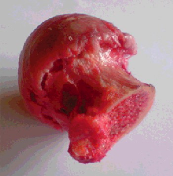
The study was approved by the local ethics committee at the Orthopaedics and Trauma Clinical Centre of the Ministry of Interior (Bulgaria). Written consent forms were obtained from all patients.
Drilling system
The experiments were executed using the Orthopaedic bone-Drilling Robot ‘ODRO’ [Citation13–15]. The executive module, its power and control block and structure drawing are shown in , respectively.
Figure 3. Automatic executive drilling module of ODRO and its accessories.
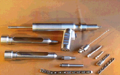
Figure 4. Power/control block of ODRO.
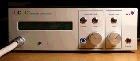
Figure 5. Structure drawing of ODRO. The numbers 1, 2 and 3 indicate the linear drive, the load cell and the rotary drive, respectively.
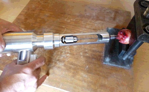
‘ODRO’ is just a prototype and is still not a tradable robot. It has not been commonly used in robotic surgery. However, a few real operations were successfully made in hospital by using ODRO. The drilling starts at the moment the device detects that the drill bit has come into contact with the bone and automatically stops when the manipulation criteria are fulfilled depending on the chosen mode. The experimental setup is shown in .
Figure 6. Experimental setup.
Note: The firm contact between the robot corpus and the bone can be seen.
Data analysis
The force signals are captured by the sensor inside ODRO. Specific sets of data are periodically sent to the PC for future analysis. The variation of the thrust force in time was graphically presented (by Microsoft Excel) and analyzed. The time was expressed in arbitrary units (AU) of measurement; 1 unit is defined as the scoring time, i.e. the interval of time between two measurements.
Results and discussion
The ultimate force (in newton) that the bone tissue can withstand is 60 N. In our experiments, such force was registered in the case of drilling the far cortex of the hip head of a 45-year-old man with a speed of 4 mm/s and a 2.8-mm drill bit (, case number 27).
Table 1. Experimental data obtained at 1000 rpm rotation speed and a drill bit diameter of 2.8 mm.
Thrust force variation during the drilling process
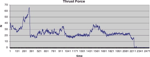
The thrust force variation depends on the zone where the drilling is executed. shows the thrust force graph when the drilling goes along the neck axis. It clearly shows the thrust force arising in the cross-section zone (500–1030 AU) as well as the hip head cortex (1430–1750 AU).
Figure 7. Thrust force as a function of time.
Note: A specimen obtained during arthroplasty in a 78-year-old male patient. Drilling along the femoral head-neck axis; maximum drilling velocity Vmax = 4 mm/s; drill bit 2.8 mm; total time 16.68 s, 2506 AU.
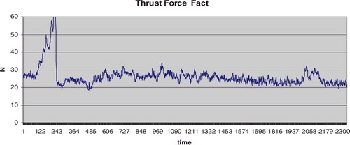
On the other hand, the thrust force stays relatively constant in the case of drilling close to the neck wall medially () with a small rise in the area of the cortex (about 2050 AU). That makes the detection of the cortex by ORDO uncertain.
Figure 8. Thrust force as a function of time.
Note: Specimen obtained during arthroplasty in an 80-year-old female patient. Drilling close to the neck wall medially; Vmax = 2 mm/s; drill bit 2.8 mm; total time 15.46 s, 2330 AU.
Thus, the successful hip head end registration together with the guaranteed stopping of drilling before the bone cartilage (approximately 2 mm) area would ensure a hole of a maximum depth, regardless of the implant position along the neck axis. The eventual damage of the joint cartilage surface in this case is not a problem. A damage with a surface of less than 6 mm2 [Citation16] is considered to have no negative results in terms of regeneration capability.
Femoral head-structure detection
We developed an algorithm for registration of the drill bit position when it reaches the hip head end during the drilling process. The translation motion control is based on the force feedback. А modified PI control law is used to calculate the new position (number of steps of the linear drive stepper motor). The numbers of steps are , where k is the discretization time interval which the linear motor (respectively the drill-bit position) must reach in a given interval ∆t of time:
Here
;
,
;
and
are feedback coefficients of the proportional and integral component of the control low;
is the measured actual thrust force;
is the reference force which the algorithm has to maintain during the drilling process. It is determined based on the thrust force for any specific object of interest.
Considering our specific task, the following comments have to be made. The hip head cortex registration depends on the bone density evaluation in the current drilling zone. Thus, an integral component Ids is formed in a sliding window in the same current drilling zone. It gives information about the bone density deviation there:where
is the dimension of Ids from the view point of sample discretization. Its value is updated after every
samples. Decreasing of Ids indicates drilling in an area of higher bone density and its increasing, vice versa, i.e. drilling in an area of lower bone density. The latter is relative to the density of neck area corresponding to Reference Force
.
A parameter ΔIds is formed as a difference between two values of Ids (obtained one after the other). It gives information about the tissue density deviation at the current drilling area. The higher the ΔIds, the larger the bone density deviation comprising the current zone and the zone drilled just before. The comparison of the ΔIds value with some appropriately chosen reference value is a criterion to take a decision for ending the hip head drilling.
The dimension of Ids from the viewpoint of the number of subtractions () ensures accurate monitoring of the trend towards increasing or decreasing the bone density and, at the same time, minimizes the ‘not typical force sensor data’ in the drilling area.
The dimension of Ids from the viewpoint of the number of samples of discretization concerns the drill bit penetration when it starts moving in a low-density area or after the whole head drilling.
Our algorithm is developed to analyze the experimental results concerning the detection of human femoral head far cortex. It has the following steps:
| (1) | Reference thrust force | ||||
| (2) | Forming of the integral component of the control low according to the bone density in the current drill bit position; | ||||
| (3) | Identification of the ‘cross section’ appearance in the area where | ||||
| (4) | Identification of the ‘cross section’ end in the area where | ||||
| (5) | Identification of the thrust force arising in the far cortex area where | ||||
The algorithm for far cortex registration described above works correctly for drilling along the neck axis. But if the drilling is executed close to the neck wall, the ‘cross section’ area stays above or below the hole. Because of that, the resistance force arising in such a case simply means that the far cortex has been reached.
The drilling zone features are not known before the drilling execution. Then an additional criterion must be involved to determine the reason for occurrence of higher bone density: the registration of the ‘cross section’ area or the far cortex. In our particular case, such a criterion for taking a decision is the moment of reaching bone structure of higher density relative to the contact point. Taking into account the schematic drawing in and the drill bit contact point with the neck, it could be considered that the ‘cross section’ area is located at a distance not greater than 25 mm from the contact point. This distance helps to determine whether the occurrence of higher density corresponds to the beginning of the ‘cross section’ area or the hip head far cortex. Then it is possible to make a decision whether to continue drilling or to stop.
For safety reasons, simultaneously with the algorithm for far cortex registration, a check for inequality ΔIds > ΔIref is being done for the purpose of hip head registration. There ΔIref is a limit value specified up to the start of drilling. Its exceeding switches on the emergency drilling stop.
Generalizing, the contact detection mechanism and the auto-stop mechanism are function of the following parameters: – resistant force before contact registration (free motion);
– measured actual thrust force;
– reference force determined for any particular object based on the thrust force;
;
,
;
,
. Here k is the discretization time interval and
is the dimension of Ids.
Experimental verification of the new criterion during the drilling process
shows an excised femoral head of a 78-year-old man and presents the experimental results obtained during its hip head drilling along the neck axis and far cortex registration.
Figure 9. Hip head, man, 78 years old.
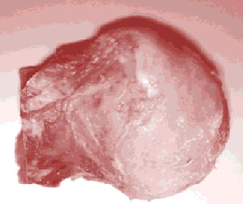
Figure 10. Hip head drilling along the neck axis and far cortex registration for a specimen obtained from a 78-year-old man.
Note: Vmax = 4 mm/s; drill bit 2.8 mm; total time 1500 s, 735 AU; n = 5. Hole depth 46.7 mm (preliminarily set depth of 53.0 mm). The blue line indicates the measured actual thrust force values of . The values of the Integral component Ids (red line) are scaled by multiplication of 10−1.
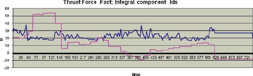
The beginning of the‘cross section’ area is at 350 AU where Ids < 0; the cortex is detected at about 610 AU where Ids again takes the value less than 0. After the contact (from 50 to 150 AU), the drilling is executed at a speed of 1 mm/s and later it continues at 4 mm/s. Taking into account the process duration, the ‘cross section’ (Ids < 0, 350 AU) appears at a distance of about 18 mm from the contact point.
A drilling regime is developed where a parameter ‘preliminarily set depth’ is used. It cannot take a greater value at any point of the drilling process. In this mode, the drilling stops automatically if just one of the following three conditions is fulfilled: hip head cortex registration, hip head end registration and reaching the preliminary set depth value. presents the results obtained for hip head end registration in the case of drilling close to the neck wall laterally.
Figure 11. Hip head end registration during drilling close to the wall laterally.
Note: 78-year-old man; Vmax = 4 mm/s; drill bit 2.8 mm; total time 13,797 s, 683 AU; n = 5. Hole depth 38.9 mm (preliminarily set depth of 53.0 mm). The blue line indicates the measured actual thrust force values of . The values of the Integral component Ids (red line) and ΔIds (yellow line) are scaled by multiplication of 10−1.
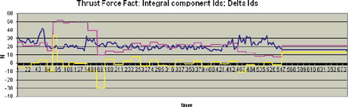
During the drilling process, there is Ids > 0. The hip head end is registered at 550 AU where ΔIds > ΔIref. The accuracy of the hip head end registration is 0.1 mm and the working area of the robot ODRO is 100 mm. Thus, the successful hip head end registration together with the guaranteed stop of drilling before the bone cartilage surface (the cartilage area thickness is approximately 2 mm) would ensure a maximum hole depth without capsule penetration.
Information about the final result appears on the display after the drilling ends. The information on the display in corresponds to the drilling process shown in and the one in corresponds to the graph in .
Figure 12. Final result of drilling along the neck axis.
Figure 13. Final result of drilling close to the neck wall laterally.
The information on the display shown in is interpreted as follows:
| – | 53.0 mm – preliminarily set depth; | ||||
| – | 46.7 – the hole depth where the drilling is finished; | ||||
| – | OK – no missing motor steps are registered; a check is done after the drilling end when the drill bit moves back to its Home position, i.e. the displayed hole depth is correct with 0.1 mm accuracy; | ||||
| – | Hip Cortex Find – stop because of registration of the femoral head far cortex. | ||||
By analogy, the information on the display shown in is interpreted as follows:
| – | 53.0 mm – preliminarily set depth; | ||||
| – | 38.9 – the hole depth where the drilling has finished; | ||||
| – | OK – no missing motor steps are registered; | ||||
| – | Hip Head End – stop because of registration of the hip head end. | ||||
For the particular case, a preliminarily set depth of 53.0 mm is taken. The aim is to indicate if the algorithm for far cortex registration or hip head end fails. The maximal length from the contact point to the apex of the femoral head is 50 mm. If the drilling stops because of the preliminarily set depth, the display information will read: 53.0 / 53.0 mm OK.
The choice of optimal implants is also based on various additional criteria. Pre-operative planning of the implant size is based on X-ray imaging. At the same time, the X-ray amplification makes corrections of the planned implant size. This problem has been addressed by a large amount of scientific research. The amplifying factor is investigated depending on the distance between the object and the X-ray source as well as the distance between the object and the X-ray film. Standardization is proposed for distances when visual evaluation is applied. Corresponding tables are created for right calculation of the image coefficient of amplification [Citation17] and correction, respectively. Additionally, these values can be made more precise by using calibration markers placed mostly in the big trochanter area. This approach is used in pre-operative digital methods. Digital X-ray images are analyzed by specific software and the right correction of the X-ray amplification is obtained [Citation18]. The maximal drilling depth determination by using the X-ray amplification correction additionally guarantees that of the risk of capsule penetration is eliminated.
Perspectives
The operative hip fractures treatment by osteosynthesis includes femur lateral cortex drilling in the trochanter area. The hole goes through the femoral neck and reaches some depth into the hip head. To preserve the tissue substance while the implants pass through, their right position is firstly determined by a special screw leading Kirshner's nails (K-nails) [Citation19]. Their small diameter (1.5 mm) allows various changes in the direction of placement without femoral head destruction. Reaching the least distance to the far cortex is possible by following the leading K-nail movement under fluoroscopic control in two projections. Any errors in the evaluation of the K-nail position relative to the cortex may either cause the nail to penetrate into the hip joint or, may lead to insufficient penetration which is not sufficient for stable implant fixation later.
The algorithm developed in this work takes into account the bone structure in the femoral neck area. It is applied for automatic detection of human femoral head far cortex. It works without the need for fluoroscopic control during the drilling process. Thus, the hole depth is optimized and the risk of penetration into the joint capsule is eliminated. As a result, information about the maximal hole depth which could be reached is obtained. Such information allows determining and calculating the right screw or implant size. This ensures its positioning in the desired hip head area and, consequently, maximal fixation strength. In case of inability to detect the head far cortex, the risk of penetration into the joint capsule is reduced to a minimum by software limitation of the maximal hole depth. The robot is responsible for this protection. Moreover, the automatic femoral head drilling decreases the operative time and minimizes the X-ray exposure of the patient and especially, of the surgical team. To the best of our knowledge, such an approach is proposed here for the first time. The known approaches for automatic bone drilling concern determination of the outer bone wall – where the drill bit goes out of the bone, i.e. the breakthrough [Citation20–22].
Up to now, we have developed algorithms for the common approach in automatic femur bone drilling: drilling only the first cortex or both cortices, setting the desired drilling depth for specific screws at a fixed preset value etc. [Citation13]. In future, we are planning to combine these algorithms with the one developed here, i.e. starting ‘as usual’ through the femur, followed by registration of the femur neck and then applying the new algorithm for the femoral head. This has the potential of becoming a successful method of automatic bone drilling for placing the implant in optimal position without (or with minimal) fluoroscopic control and without capsule penetration.
Conclusions
To the best of our knowledge, this is the first report of an algorithm for automatic human femoral head far cortex detection that is based on the bone structure in the femoral neck area. The approach applied here has the advantage of predicting the optimal hole depth, coupled with eliminating (or minimizing) the need for fluoroscopic control during the drilling process and the risk of capsule penetration. This makes it possible to determine and calculate the most appropriate screw or implant size and ensures maximal fixation strength through precise positioning in the desired area of the hip head. The robotized device furthermore includes software limitation of the maximal hole depth in order to eliminate the risk of penetration into the joint capsule even in cases when the algorithm is unable to detect the head far cortex. What is more, the automatic femoral head drilling decreases the operative time and minimizes the X-ray exposure of both the patient and the surgical team. Future work will focus on combining the algorithm proposed here with previous ones with the aim to develop a reliable method of automatic bone drilling for placing the implant in optimal position without (or with minimal) fluoroscopic control and without capsule penetration.
Disclosure statement
No potential conflict of interest was reported by the authors.
Additional information
Funding
References
- Sugano N. Computer-assisted orthopedic surgery. J Orthop Sci. 2003;8:442–448. DOI:10.1007/s10776-002-0623-6
- Finley DS, Nguyen NT. Surgical robotics. Curr Surg. 2005;62(2):262–272. DOI:10.1016/j.cursur.2004.11.005
- Gomes P. Surgical robotics: reviewing the past, analysing the present, imagining the future. Robot Comput-Integr Manuf. 2011;27:261–266. DOI:10.1016/j.rcim.2010.06.009
- Beasley RA. Medical robots: current systems and research directions. J Robotics. 2012 [cited 2017 Oct 02];2012:40161. [14 pages]. DOI:10.1155/2012/401613
- Allotta B, Giacalone G, Rinaldi L. A hand-held drilling tool for orthopedic surgery. IEEE Trans Mechatronics. 1997;2(4):218–229. DOI:10.1109/3516.653046
- Dennison E, Mohamed MA, Cooper C. Epidemiology of osteoporosis. Rheum Dis Clin North Am. 2006;32:617–629. DOI:10.1016/j.rdc.2006.08.003
- Panula J, Pihlajamäki H, Mattila V, et al. Mortality and cause of death in hip fracture patients aged 65 or older – a population-based study. BMC Musculoskelet Disord. 2011 [cited 2017 Sep 20];12:105. DOI:10.1186/1471-2474-12-105
- Matre K, Havelin LI, Gjertsen J-E, et al. Sliding hip screw versus IM nail in reverse oblique trochanteric and subtrochanteric fractures. A study of 2716 patients in the Norwegian Hip Fracture Register. Injury. 2013;44(6):735–742. DOI:10.1016/j.injury.2012.12.010
- Butler M, Forte M, Kane RL et al., Treatment of common hip fractures. Evidence Report/Technology Assessment No. 184, AHRQ Publication No. 09-E013. Rockville (MD): Agency for Healthcare Research and Quality; 2009. Available from: www.ahrq.gov
- Kastelov R, Yordanov T, Bonchev B. A three-year clinical experience with treatment of unstable fractures of the proximal femur using minimally invasive surgical technique. Poster session presented at: 14th Congress of the EFFORT; 2013 Jun 5–8; Istanbul, Turkey.
- Kwon JY, Naito H, Matsumoto T, et al. Osteocyte apoptosis-induced bone resorption in mechanical remodeling simulation – computational model for trabecular bone structure. In: Ntuli TM, editor. Apoptosis and medicine. Rijeka: InTech; 2012. DOI: 10.5772/50301
- Baumgaertner MR, Curtin SL, Lindskog DM, et al. The value of the tip-apex distance in predicting failure of fixation of peritrochanteric fractures of the hip. J Bone Joint Surg [Am]. 1995;77:1058–1064. DOI:10.2106/00004623-199507000-00012
- Boiadjiev G, Kastelov R, Boiadjiev T, et al. Design and performance study of an orthopaedic surgery robotized module for automatic bone drilling. Int J Med Robot. 2013;9(4):455–463. DOI:10.1002/rcs.1479
- Boiadjiev G, Kastelov R, Boiadjiev T, et al. Automatic bone drilling – more precise, reliable and safe manipulation in the orthopaedic surgery. J Theor Appl Mechanics. 2016;46(2):51–64. DOI:10.1515/jtam-2016-0010
- Boiadjiev T, Boiadjiev G, Delchev K, et al. Far cortex automatic detection aimed for partial or full bone drilling by a robot system in orthopaedic surgery. Biotechnol Biotechnol Equip. 2017;31:200–205. DOI:10.1080/13102818.2016.1234947
- Convery FR, Akeson WH, Keown GH. The repair of large osteochondral defects. An experimental study in horses. Clin Orthop Relat Res. 1972;82:253–262. DOI:10.1097/00003086-197201000-00033
- Eggli S, Pisan M, Muller ME. The value of preoperative planning for total hip arthroplasty. J Bone Joint Surg Br. 1998;80-B(3):382–390. DOI:10.1302/0301-620X.80B3.7764
- Davila JA, Kransdorf MJ, Duffy GP. Surgical planning of total hip arthroplasty: accuracy of computer-assissted EndoMap software in predicting component size. Skeletal Radiol. 2006;35:390–393. DOI:10.1007/s00256-006-0106-4
- Kastelov R, Bonchev B. The choice of implant in the treatment of unstable trochanteric fractures in the elderly patients. Paper presented at: 2nd Fragility Fractures Network Global Congress; 2013 Aug 29–31; Berlin, Germany.
- Lee W-Y, Shih C-L. Control and breakthrough detection of a three-axis robotic bone drilling system. Mechatronics. 2006;16(2):73–84. DOI:10.1016/j.mechatronics.2005.11.002
- Aziz MH, Ayub MA, Jaafar R. Real-time algorithm for detection of breakthrough bone drilling. Proc Eng. 2012;41:352–359. DOI:10.1016/j.proeng.2012.07.184
- Taha Z, Salah A, Lee J. Bone breakthrough detection for orthopedic robot-assisted surgery. In: Cakravastia Andi, editor. Proceedings of the 9th Asia Pacific Industrial Engineering & Management Systems Conference (APIEMS 2008); 2008 Dec 3–5; Nusa Dua, Bali, Indonesia. Bandung (Indonesia): Department of Industrial Engineering Institut Teknologi Bandung and Department of Industrial Engineering, Institut Teknologi Sepuluh Nopember; 2008. p. 2742–2746.