
 ?Mathematical formulae have been encoded as MathML and are displayed in this HTML version using MathJax in order to improve their display. Uncheck the box to turn MathJax off. This feature requires Javascript. Click on a formula to zoom.
Abstract
To facilitate the construction of intact model of fractured bone and satisfy the representation of fracture information, a novel approach of constructing a restored model of fractured femur (RMFF) based on anatomic feature is put forward. First, the fracture mesh model is divided into major segments by removing the comminuted part. Next, through the constraint-based deformation of parameterized template with a few valid parameters of fracture segments, the intact reference surface model is constructed to represent normal anatomy of individual fractured femur, and the feature points of the reference model are extracted. Then, based on the solution of matrix equations of rigid registration between available feature points of fracture segments and the ones of the reference model, major fracture segments are piecewise adjusted to original proper positions respectively. Finally, the internal part of the reference model cut with the boundary curves of major segments is employed to represent the surface of the comminuted part, and the surface of the comminuted part is merged with adjusted segments to acquire the intact model. Simulation experimental results show that RMFFs can be reconstructed rapidly and accurately according to available information of the fractured femur.
Introduction
With the trend of global aging as well as traffic accident increasing, pathological degeneration and violent injury have become two major causes of human femoral fractures [Citation1]. Advancements in Computer Aided Orthopedics Surgery (CAOS) promote extensive application of fracture fixation in clinical surgery, and have increased the success rate of fracture treatment [Citation2]. As we all know, three-dimensional (3D) models play a significant role in the precise representation of the anatomic morphology of a patient’s skeleton during the orthopedic diagnosis, surgical planning, simulation surgery and implant selection [Citation3, Citation4]. Therefore, accurate model construction of human bone, especially restored fracture model containing individual fracture marks [Citation5], is of great significance in digital preoperative planning for doctors and in guiding the development of orthopedic implants for medical equipment manufacturers. Thus, accurate model construction becomes a fundamental part in the improvement of the surgical treatment of fractures.
Three-dimensional modeling of human bones can be achieved with individual continuous tomography images by employing image processing, image segmentation, surface extraction and mesh simplification [Citation6]. However, high-dose irradiation outputted by scanning equipment may increase the potential harm to patients’ health [Citation7]. To overcome this drawback, the template-based strategy was proposed in the description of typical anatomic features of bones. By employing interpolation, free-form deformation, nonrigid registration, Laplacian deformation and other algorithms, previously created template models were recursively modified to match the individual 2D information extracted from a few digital radiography (DR) images [Citation8–11]. Nevertheless, both the lack of typical skeletal features set in the template model and the calibration error of DR images before contour extraction [Citation6], are still large challenges in improving the modeling precision. In view of the fact that statistical shape modeling (SSM) has the advantages in delineating average shape and variable deviations of a given population [Citation12], SSM-based methods have been increasingly applied in 3D modeling to solve the issue of how to obtain a representative reference model of bones. In accordance with individual plane images [Citation13] and 3D point sets [Citation14], femur models can be quickly generated by reconfiguring the SSM model. Consequently, the robustness and accuracy of 3D modeling of individual bones are greatly improved.
Compared to the overall construction of bones, the accurate reconstruction of anatomic structure and the description of major fracture marks are more useful and meaningful in related medical applications, such as preoperative planning, surgery simulation as well as orthopedic implant design, and this is very important for the improvement of fracture treatment. Therefore, how to restore fracture segments and reconstruct the original anatomy model of damaged bones is of great significance in orthopedic modeling. But, so far, there are few technical details available regarding the anatomic restoration and fracture reduction of damaged models. Manual splicing of fracture fragments can achieve an approximate reduction of fracture segments [Citation15, Citation16]; however, the precision of the reconstructed model is largely dependent on medical experience. What is more, the entire restoration process is time-consuming and laborious, and it is hard to reuse. In clinical practice, doctors often adopt the mirror image of the contralateral native bone of a patient to represent the damaged bone anatomy to avoid the dull and onerous manual stitching. Nevertheless, because the human skeleton is not entirely contralateral [Citation17], the original anatomic structure and shape described using the mirror bone image [Citation18, Citation19] may lead to underlying functional malformation post operation [Citation20]. Although point registration is a promising technology for the rapid alignment between 3D models [Citation21, Citation22], existing methods can seldom be employed in fracture anatomic restoration because of two challenges. One is the fact that the rotation and displacement of segment parts in the fractured bone directly lead to a change of normal anatomic appearance. The other challenge is that any individual bone cannot be selected as the reference object for the significant difference of shape and structure.
In summary, all of the previous methods pay little attention to the anatomic feature description, and can hardly achieve quick and correct reconstruction of fractured bones. These methods are still far from being completely satisfactory for the users. As a result, how to restore the 3D model of an individual bone is still an urgent issue to be solved .
This work puts forward a novel approach of constructing a restored model of fractured femur (RMFF) to restore major fracture segments to their original normal positions rapidly and to construct the intact model with key fracture marks, based on the extraction and registration of typical anatomic features of human skeleton.
Subjects and methods
In this study, 20 healthy right femurs of Chinese female volunteers living in Southern Jiangsu of China with no previous trauma and no history of diseases were selected and scanned by 64-slice CT (MSCT, Aquilion 64, Toshiba, Zoetermeer, Netherlands) to acquire mesh models. The average age of the volunteers was 37.3 ± 6.8 years, (range: 31 to 46 years). The average height was 158.8 ± 5.6 mm (range: 154.3 to 163.7 mm). On this basis, simulated models were generated by cutting intact models to represent AO/OTA 32B3 type fractures.
Ethics statement
The institution’s internal review board approved the protocol and each patient provided an informed consent form before this study.
Overview of proposed approach
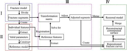
Taking a mesh model of fractured bone pre-generated from CT images as input, the approach of constructing restored model of fractured femur (RMFF) included the following steps based on previous research works [Citation23–26].
Step 1. Remove comminuted parts of the fractured bone, and divide the intact model into major segments.
Step 2. Create the intact reference surface model of individual femur based on the constraint deformation of the parameterized template with a few valid parameters measured from the fracture segments [Citation23], and extract the feature points of the reference model to represent the original shape and structure of the fractured bone.
Step 3. Solve for transformation matrices of the rigid registration between available feature points of fracture segments and the ones of the reference model, and then piecewise adjust major fracture segments to their original proper positions according to the matrices respectively.
Step 4. Cut the internal part of the reference model cut with the boundary curves of major segments to create the surface of the comminuted part, and merge it with adjusted segments to acquire the intact model of individual bone.
The complete workflow of reconstructing the RMFF from individual fractured model is shown in . Steps 2–4 are the most important ones of the above four steps, which will be expounded in the following sections.
Figure 1. Flow diagram of constructing restored model based on anatomic features.
Extracting anatomic features
The description of anatomic features of femur shape and structure and the extraction of effective feature information about the damaged bone are two important prerequisites for accurate anatomic reconstruction of the individual fracture restored model. Therefore, the methods of defining and extracting anatomic features will be discussed in this section.
Defining anatomic features
Due to the significant differences in shape and structure of the femur, any individual bone is not suitable to delineate the typical anatomic features of the femur. Therefore, in this study, an average model pre-generated from healthy adult female femur scans in southern Jiangsu province of China [Citation24] served to shield individual differences and represent the typical anatomic information of a specific population.
The construction of skeleton models traditionally uses a large number of discrete 3D points, and the points have different contributions to accurately describe the shape and structure of the bone of interest. Therefore, reasonable extraction of feature points having significant medical semantics not only can simplify the computational complexity of model processing, but also is beneficial to decrease the noise sensitivity of the 3D model and to improve the description accuracy of the femur anatomy.
On account of the irregular anatomic shape and the significant function of each feature region (e.g. head, neck, trochanter, shaft and condyle), it is very hard to delineate the 3D structure and shape of the bone effectively by the traditional method such as B-rep [Citation27]. In this work, femur features were represented in two levels, (i.e. functional structure and anatomic shape). In combination with the medical significance of the anatomic feature axis reported in the researches of parameter measurement and morphological analysis, the anatomic feature axes including the neck axis Nx, the proximal shaft axis Px and the distal shaft axis Dx were defined to characterize the overall anatomic structure of bones. These feature axes were created by fitting a number of feature points of structure (Ps) which are equidistant on the axis, as shown in .
Figure 2. Feature definition of femur anatomy.
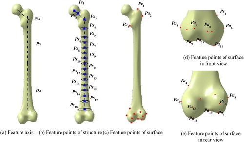
In addition, to describe the obvious visual geometric properties on the surface and their medical anatomic significance, a few intuitive points of anatomy (Pa) located at the convex or concave surface of the proximal and the distal regions (such as small trochanter) were extracted as shown in . The detailed definitions of Ps and Pa are listed in Appendix A and Appendix B.
Therefore, the anatomic feature AF of the femur may be characterized with two-level point sets (Ps and Pa), and its formal definition was given below:
(1)
(1)
where, Psi and Pai are the points in Ps and Pa, and m, n are the point number of two sets, respectively.
Extracting feature points
Ps extraction
The center of the femur head manifests as an approximate hemisphere, and it is of great significance in anatomy. The head center Ps1 was garnered by point fitting of the head region based on the least-square principle:
(2)
(2)
where Jh is the head fitting function, and Rh is the fitted radius of the hemisphere.
The center of the neck isthmus Ps2 was fitted from the points of the neck region by using the method described in a previous study [Citation28] as follows:
(3)
(3)
where Jn is the neck fitting function, xd, yd are the maxim values in x and y direction respectively, and
is the angle.
The shaft of the femur appears outward, and its detailed structural features such as the cadre's curvature can be hardly described with only one anatomic axis. Therefore, in this study, the femur was divided into proximal and distal parts based on the center of the femoral shaft isthmus, and the proximal axis Px and distal axis Dx were created by the fitting of the centers of each section with the following steps:
Step 1. Obtain the average value of all vertices and set to the center point of the femoral model Ps10.
Step 2. Acquire the section plane Pl passing through the Ps10 with the smallest region.
Step 3. Generate proximal axis Px and distal axis Dx by fitting center points of section plains parallel to Pl.
Step 4. Discretize Px and Dx into the continuous equidistant points Ps4 to Ps9 and Ps11 to Ps18 as shown in .
Figure 3. Extracting feature points of femur shaft.
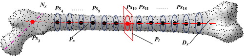
Finally, create Ps3, that is the intersection point between Px and Nx, in which, Nx passes through Ps1 and Ps2.
Fa extraction
The local height of the vertex has an advantage on the curvature description of the femur surface, and was employed to represent the position and convexity of the vertices. The absolute value of local height is greater, and the concave and convex parts at the corresponding point are more obvious. So, based on the apex height mapping principle, Pa was extracted with the following steps:
Step 1. Calculate the normal vector of the edge between the vertex V and its adjacent one (), and define NB as follows:
Figure 4. Definition of vertex height.
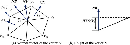
in which, NT is the normal vector of the vertex V, m is the number of triangular mesh associated with V, NT(Ti) is the normal vector of the triangular mesh Ti, AT(Ti) is the proportion of Ti.
Step 2. Obtain the height value between V and its adjacent one Vi:
where, HV is the projection in the vector NB(V,Vi).
Step 3. Compute the H value of V:
Step 4. Extract the feature point set of Pa based on H.
Repositioning major fracture segments
Besides the different description of the surface shape and the normal anatomic structure between individual bones, another key challenge for the construction of the patient's fracture restored model is how to adjust the fracture segments automatically and accurately to their correct positions based on the existing feature information. What is more, it is also the primary guideline to enhance the efficiency and accuracy of fracture restoration in this study.
Constructing individual reference model
To ensure that the femoral parametric feature model represents the individual structure and shape [Citation23], we created a reference model based on the existing parameters measured from the individual femur to describe the anatomic features of the fractured bone, and to guide the fracture repositioning. The major steps are as follows:
Step 1. Obtain a few of anatomic parameters such as head radius (Hr), head height (Hh) and condyle width (Clmc) of the damaged bone MFI, and then select the major fracture segments MFIi, as shown in ;
Figure 5. Steps of reference model construction.
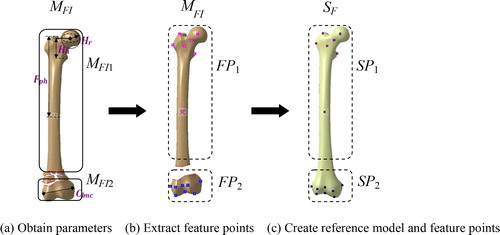
Step 2. Remove the parts of the comminuted segments, and extract the available feature points FPi of each fracture segment MFIi, as shown in ;
Step 3. Create an individual reference model SF by modifying the parameterized bone template with constraints, and extract the feature points SPi corresponding to each segment in the fractured model, as shown in .
Adjusting fracture segments
In complex fractured human bone models, the major fracture segments manifest themselves as rigid parts, and a small number of local fractures frequently appear comminuted. By using rigid alignment algorithms, the intact bone can be quickly adjusted to its original position. However, displacement and dislocation of fracture segments commonly appear in fractured femur models. Therefore, it is hard to accurately restore the segments to their original anatomic positions only by direct matching between the dislocation models and the reference ones. In this study, a segmented rigid registration method based on skeletal features is proposed. In it, rigid registration matrices H between point sets FPi and SPi were calculated based on the improved ICP registration algorithm. On the basis of the above, the fracture segment models MFIi were rotated and translated according to the specific transformation matrices R and T of H respectively.
(8)
(8)
(9)
(9)
(10)
(10)
where, R is the rotation matrix,
and
are the rotation angles in x, y and z direction, respectively, T is the translation matrix, V is the transformation vector and S is the scaling factor.
Compared with point set Pa, point set Ps used to create the anatomic axis is more important for the fracture restoration. Therefore, to improve the contribution of the structural feature points in rigid registration, a weighting factor is added to improve the ICP algorithm, in which, the
values of Ps are commonly larger than the one of Pa. The algorithm for adjusting the fracture segments based on feature points consists of the following major steps:
Step 1. Select a point FPij from FPi;
Step 2. Find the point SPij from SPi with the minimization of ǁSPij – SPijǁ;
Step 3. Solve for transformation matrix, and minimize the error Ei:
Step 4. Update FPij to FPij’ as follows:
Step 5. Calculate the average distance d between feature points;
Step 6. Return to Step 2;
Step 7. Stop iteration when d is less than the threshold or the number of iterations reaches the upper limit, and recorder Hi;
Step 8. Transform MFIi to obtain MFCi based on Hi;
Step 9. Group MFCi, and obtain the restored model MFC.
Constructing intact restored fracture model
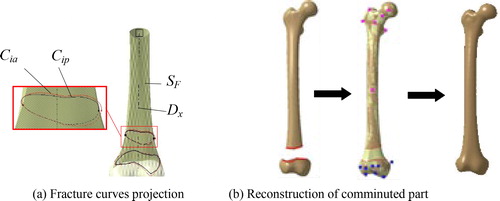
In the treatment of complex femoral fractures, especially comminuted fractures, fracture fragments are hard to fix. As a result, the parts that are too tiny need to be removed in the surgery [Citation7]. To reconstruct the complete anatomic model of an individual fracture, the surface of the comminuted region can be represented with the corresponding local part of the reference model with the following processes. Firstly, the major fracture curves Cip, defined as the segment boundaries near to the fracture site, were extracted based on the restored segments. Secondly, the reconstructed fracture curves Cia were generated by projecting Cip to the reference model SF along the normal direction of the distal axis Dx, as shown in . Then, the part of SF between Cip was cut to represent the surface of the comminuted region. Finally, the individual complete surface model was reconstructed by combining the surfaces of fracture segments with the reconstructed model of the comminuted region based on smoothing technology, as shown in .
Figure 6. Construction of individual intact restored fracture model.
Results and discussion
To evaluate and verify the feasibility of the methodology and algorithms presented in this work, simulation experiments were carried out to illustrate the modeling efficiency and the reconstruction accuracy of the proposed approach. Considering that it is hard to characterize the intact anatomic shape and structure of a real fractured bone, intact mesh models were cut at the distal end to create a simulation fracture model of AO/OTA 32B3 type fracture, and the simulation fracture models were adopted to evaluate the accuracy of fracture reduction.
Computation time
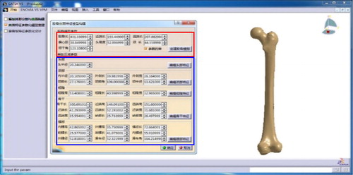
Using a 2.2GHz i5-5200u CPU with 4G RAM, the proposed methodology and algorithms were implemented in the software environment including MATLAB 7.11.0, Microsoft Visual Studio 2008 and CATIA V5 R21 integrated with ‘CAA and RADE’ toolkits. With a few available parameters measured from the simulation fracture model, the reference model for an individual femur was constructed in the developed experimental platform ().
Figure 7. Experimental platform of constructing individual reference model.
Each vertex number of the simulation fracture model was simplified to around 5000. shows a case of model reconstruction and the experimental result for Sample A. Average values of time consumption in each stage were recorded and listed in .
Figure 8. Reconstruction results of Sample A.
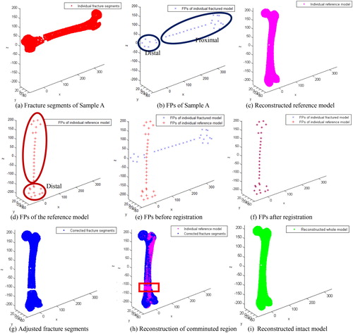
Table 1. Average time consumption of stages.
Reconstruction accuracy
To evaluate the reconstruction accuracy of the proposed method, we compared individual restored models against corresponding reference models and their original normal anatomic models respectively. The Hausdorff distance [Citation29] served as the evaluation indicator to quantify the reconstruction error of the individual sample; model error ME was formulary defined as follows:
(12)
(12)
where A is the equal step sampling point set in the individual restored model, A= {a1, a2, …, an}; B is the equal step sampling point set in the individual reference model or original normal model, B= {b1, b2, …, bn}.
A shape comparison between the restored model and its reference model of two samples (Sample B and Sample C) are shown in , and a detailed comparison of the anatomic regions (e.g. head, condyle and shaft) between the reconstructed model and the original model are shown in . The average error of each anatomic region is listed in . Because of the various degree of shape difference between an individual bone with the average bone, various differences of the reconstructed individual reference anatomy based on the parameterized feature template were found (), and these errors are similar to that reported in the literature [Citation23]. In addition, the individual restored fracture model has a strong similarity with the original normal anatomic model. Because of that, the reconstruction error can be limited within 0.3 mm or even lower as shown in . Thus, the restoration results can meet the needs of further medical applications.
Figure 9. Shape comparisons between reconstructed and reference model.
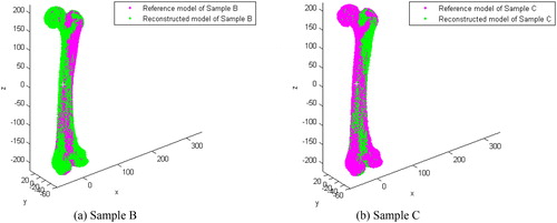
Figure 10. Shape comparisons between reconstructed and original model.
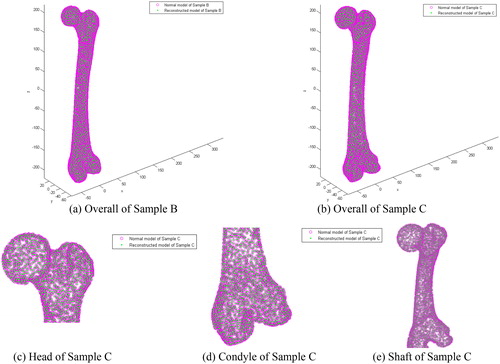
Table 2. Average error of sample model reconstruction (mm).
Method comparison
Compared with certain other approaches, the suggested method for supporting the construction of RMFFs based on anatomic features has a number of advantages. It is a more efficient approach for anatomy feature representation of individual bones (). (i) The referential model may be quickly and efficiently acquired from existing fracture models. (ii) The improved ICP algorithm of this study may contribute to the slight improvement of modeling efficiency and construction accuracy. (ii) After adjustment of the fracture segments, the major fracture curves can be atomically reconstructed to direct many medical applications. Still more, through some available data extracted from existing fractured models, it is easier and more convenient for a user to construct the restored model of fractured bones.
Table 3. Comparison of existing methods of restoring fractured bones.
The key objectives, such as the length restoration and the correct alignment of various featured parts, should be accurately achieved in reconstructing restored fracture models. Anatomic axes and feature points are certainly capable of describing the functional structure and surface shape of the femur. By using the existing parameterized template model, the reference model and feature points of individual bone can be quickly constructed based on a little valid information of the fractured bone. With segment-based rigid registration of a limited number of feature points, the time-consumption of the overall rigid registration between a large number of point sets could be effectively addressed, and the efficiency of model reconstruction can be slightly improved.
The main significance and characteristics of this work are as follows. (i) It defines key features for accurate description of the anatomic features of the femur in two levels of surface point set and structure point set, and provides the automatic methods for feature extraction. (ii) It provides a method for automatic and accurate transformation of major fracture segments to their original positions based on feature points by improving the ICP algorithm. (iii) It extends the existing methodology for intact femur modeling, and provides the major fracture marks for further medical applications.
The proposed method of constructing a restored model constitutes a very promising and useful extension of anatomic features for feature-based modeling. However, some directions must be researched in future work, including the following avenues of investigation: (i) The restoration and reconstruction of solid model of fracture bones would be studied to meet more needs of digital orthopedic applications. (ii) More powerful description method of anatomic features must to be researched to enhance the medical semantics in bone modeling. (iii) Depth cooperation with medical personnel has to be strengthened to study the optimal method of reconstruction of different types of fracture models.
Conclusions
To facilitate the representation of the original normal anatomic features of fractured bones and to avoid manual stitching, this paper proposes a mechanism for constructing a restored model of human fractured femurs according to the specific information of damaged bones. Anatomic features characterized in two levels (functional structure and surface shape) are defined as key factors according to prior medical knowledge to guide the restoration of dislocated segments to their original normal positions in fracture bones. The method simplifies the process of fracture segment restoration by replacing a large number of vertices in lower level with a few semantic feature points, and can improve the reconstruction efficiency. Although there are some errors in the reconstruction of the individual referent model, the information of the individual skeletal anatomy and the anatomic structure can be reconstructed accurately. This research indicates that for the first time we have proposed a novel method for restoring fracture segments from existing fractured femur models rather than manually, and provides an effective technical tool for the accuracy improvement of individual restored fracture models.
Disclosure statement
No potential conflict of interest was reported by the authors.
Additional information
Funding
Related Research Data
References
- Hierholzer C, Von R, Pötzel T, et al. Outcome analysis of retrograde nailing and less invasive stabilization system in distal femoral fractures: A retrospective analysis. Indian J Orthop. 2011;45:243–250.
- Zhong S, Yin Q, Zhang Y, et al. Clinical digital orthopedics: the innovation of theoretical system and clinical application. Beijing (China): People’s Military Medical Press; 2011.
- Jimenezdelgado JJ, Paulanogodino F, Pulidoramramirez R, et al. Computer assisted preoperative planning of bone fracture reduction: simulation techniques and new trends. Med Image Anal. 2016;30:30–45.
- Majstorovic V, Trajanovic M, Vitkovic N, et al. Reverse engineering of human bones by using method of anatomic features. CIRP Ann Manufact Technol. 2013;62:167–170.
- Poelert S, Valstar E, Weinans H, et al. Patient-specific finite element modeling of bones. Proc Inst Mech Eng H. 2013;227:464–478.
- Baishali G, Santanu M. 3D modeling of X-ray images: a review. Int J Comput Appl. 2015;132:40–46.
- Mccollough C, Primak A, Braun N, et al. Strategies for reducing radiation dose in CT. Radiol Clin N Am. 2009;47:27–40.
- Oliveira F, Tavares J. Medical image registration: a review. Comput Methods Biomech Biomed Eng. 2014;17:73–93.
- Zhang B, Sun J, Chi Z, et al. 3D reconstruction of patient-specific femurs using Coherent Point Drift. Telkomnika 2013;11:1101–1110.
- Galibarov P, Prendergast P, Lennon A. A method to reconstruct patient-specific proximal femur surface models from planar pre-operative radiographs. Med Eng Phys. 2010;32:1180–1188.
- Karade V, Ravi B. 3D femur model reconstruction from biplane X-ray images: a novel method based on Laplacian surface deformation. Int J Cars 2015;10:473–485.
- Sarkalkan N, Weinans H, Zadpoor A. Statistical shape and appearance models of bones. Bone 2014; 60:129–140.
- Yu W, Zheng G. 2D-3D regularized deformable b-spline registration: application to the proximal femur. Int Symp Biomed Imaging 2015;829–832.
- Bernard F, Salamanca L, Thunberg J, et al. Shape-aware surface reconstruction from sparse 3D point-clouds. Med Image Anal. 2017;38:77–89.
- Longtao R, Yunpeng Z, Zhijian G, et al. Computer-aided personalized anatomic plated of the distal femur. J Clin Rehabil Tissue Eng Res. 2011;15:2309–2312.
- Xiaoguang S, Jitan Z, Peng D. Personalized design for dissection steel plate based on CT picture and reverse engineering. Mach Des Manuf. 2011;7:161–162.
- Dimitriou D, Tsai TY, Yue B, et al. Side-to-side variation in normal femoral morphology: 3D CT analysis of 122 femurs. Orthopaed Traumatol Surg Res. 2016;102:91–97.
- Hu L, Zhang J, Li C, et al. A femur fracture reduction method based on anatomy of the contralateral side. Comput Biol Med. 2013;43:840–846.
- Buschbaum J, Fremd R, Pohlemann T, et al. Computer-assisted fracture reduction: a new approach for repositioning femoral fractures and planning reduction paths. Int J Cars 2015;10:149–159.
- Ollivier M, Laumonerie P, Liarno S, et al. Which factors influence proximal femoral asymmetry? Clin Case Rep. 2018;100B:839–844.
- Jian B, Vemuri B. Robust point set registration using Gaussian mixture models. IEEE Trans Pattern Anal Mach Intell. 2011;33:1633–1645.
- Senin N, Colosimo BM, Pacella M. Point set augmentation through fitting for enhanced ICP registration of point clouds in multisensor coordinate metrology. Robot Comput Integr Manuf. 2013;29:39–52.
- Chen X, He K, Chen Z, et al. Construction of femur model based on parametric surface feature. J Comput-Aided Des Comput Graph. 2015;27:2367–2375.
- Chen X, He K, Chen Z, et al. Quick construction of femoral model using surface feature parameterization. Mol Cell Biomech. 2015;12:123–146.
- Chen X, He K, Chen Z, et al. A parametric approach to construct femur models and their fixation plates. Biotechnol Biotechnol Equipment 2016;30:1–9.
- Chen X, He K, Chen Z. A novel computer-aided approach for parametric investigation of custom design of fracture fixation plates. Comput Math Methods Med. 2017;2017:1–7.
- Sunil VB, Agarwal R, Pande SS. An approach to recognize interacting features from B-Rep CAD models of prismatic machined parts using a hybrid (graph and rule based) technique. Comput Ind. 2010;61:686–701.
- Byoung-Keon P, Ji-Hoon B, Bon-Yeol K. Function-based morphing methodology for parameterizing patient-specific models of human proximal femurs. Comput-Aided Des. 2014;51:31–38.
- Dekkers E, Pawlicki R, Pawlicki R, et al. A sketching interface for feature curve recovery of free-form surfaces. Comput-Aided Des. 2011;43:771–780.