
ABSTRACT
The recently developed intelligent excavation robot in Korea is a fully automated excavator equipped with global 3D modeling capabilities for an entire earthwork site and an intelligent task planning system. The intelligent excavation robot includes features such as autonomous driving, 3D surround modeling, autonomous excavation, loading, etc. An intelligent excavation robot features technology that allows for accurate recognition of objects near the excavator, including the terrain of surrounding environments, location of obstacles in the excavator’s path, and any approaching trucks and moving people. Such technology is critical to ensuring work quality and safety. In this study, we develop the hardware for a 3D surround laser sensing system that enables 3D image modeling of the terrain surrounding an intelligent excavation robot. By mounting a sensor onto an intelligent excavation robot, we conducted performance tests to determine the robot’s 3D modeling capabilities of the terrains and obstacles at an actual earthwork site. The experimental results are applied to an object recognition system for detecting the properties of the terrain of the workspace around the excavator, any approaching people, trucks, obstacles, etc. The proposed hardware includes a wide range of applications in the development of future automated construction equipment.
1. Introduction
1.1. Backgrounds and purpose
Excavators are some of the most notable construction equipment used for earthworks. Excavators perform a wide range of tasks such as cutting, banking, gathering, loading, leveling, and grading earth. The number of registered excavators worldwide is increasingly on the rise, and there are several attachments to excavators that are under continuous development, making excavators more effective for earthworks.
Research on automated excavation first began with unmanned, remote-controlled excavators developed by Japan in the 1980s, and some of the prominent studies that followed include the autonomous loading system (Cannon Citation1999; Singh and Simmons Citation1992; Stentz et al. Citation1999) developed by Carnegie Mellon University in the 1990s; the autonomous hydraulic excavator (Yamamoto et al. Citation2009) developed by the Public Works Research Institute (PWRI) in 2008, and the intelligent excavation robot (IES) developed by Korea in 2011. Among these, the intelligent excavation robot (IES) recently developed by Korea is a fully automated excavation robot that is capable of autonomous driving, 3D modeling, excavation task planning, autonomous excavation, loading, etc. IES features global 3D modeling capabilities of the entire worksite and an intelligent task planning system. To develop such an intelligent excavation robot, the technology that allows for accurate recognition of objects near the excavator, including the terrain of surrounding environments, the location of obstacles in the excavator’s path, any approaching trucks and moving people, forms the core technology that is critical to ensuring work quality and safety.
To create three dimensional models of the surrounding terrains and approaching objects around an excavator, Stentz et al. (Citation1999) utilized two-axis laser scanners mounted on the excavator to scan and recognize trucks; whereas, Yamamoto (Citation2008) used GPS (global positioning system) and a direction sensor installed on a truck that was designed to operate in harsh environments to accomplish excavation operations. In the study by Stentz et al. (Citation1999), unless an excavator is situated on top of an elevated bench and a truck stops at a designated location, it can be difficult to recognize either the truck or any other nearby object. In addition, Yamamoto’s (Citation2006) study involved multiple loading trucks that were outfitted with GPS and direction sensors, which are both expensive, and any errors in the sensor data would result in a collision between the bucket of the excavator and the truck, posing another serious problem.
Therefore, to enable 360 degrees 3D modeling of the surroundings around an intelligent excavation robot, this study develops hardware for a new type of 3D surround sensing system that minimizes blind spots and offers prompt, accurate modeling of surrounding objects in a wide variety of terrains. In addition, we install the developed sensor onto an intelligent excavation robot to test its performance using actual earthwork site terrains and obstacles. It is anticipated that the sensing system proposed in this study will provide the necessary support for accurate, fully automated excavation operations, presenting wide applications in the development of automated construction equipment.
1.2. Study scope and methodology
3D surround sensing technology refers to technology that uses geometric data on the terrain of the local area surrounding an intelligent excavation robot and nearby objects. The data is used to create three-dimensional models, and the three-dimensional geometric information captured from the excavator surroundings is then fed into object recognition algorithms to recognize terrains, people, trucks, obstacles, etc. The geometric data is ultimately used to create paths for loading trucks and to avoid obstacles. The scope of this research is only limited to developing hardware for the 3D surround sensing system, which will be used to create three-dimensional models of local terrains and objects surrounding the excavation robot. Real-time data processing of the 3D surround sensing system, including object recognition algorithms that separately recognize terrains and objects from three-dimensional geometric data, will be later discussed in subsequent research. The methodology used in this research is as follows:
1.2.1. Analysis of prior work and considerations for system hardware design
In this study, we examine the research and development status of domestic and overseas 3D surround modeling technologies by focusing on prior research work on automated earthmoving equipment and analyzing their problems. Based on the problems identified, we identify some of the considerations that are required to develop a 3D surround sensing system for the intelligent excavation robot.
1.2.2. Analysis of the optimal location of the 3D surround sensor
Excavation operations mostly involve soil digging, and 3D image modeling of a digging area below the ground without any blind spots requires an analysis of where the sensor should be located on the intelligent excavation robot. In this study, we identify the right location of the sensor that minimizes blind spots in the creation of three dimensional models of the local area around the intelligent excavation robot.
1.2.3. Hardware design of the 3D surround sensor
Our prior research employed a 2D laser scanner as an ideal sensor for the intelligent excavation robot. As we employ the sensor, we perform an analysis of its sensing area, instrument movement direction, location of rotational axis, sensor rotation method, etc. and design a layout of the sensing system. We also review the driving part, center of gravity for rotation, scanning area, sensor installation method, etc. in a detailed design.
1.2.4. 3D surround sensor installation and field test
In this study, we build the hardware for a 3D surround sensor; install the hardware onto the intelligent excavation robot; and execute tests. We also develop data processing software for the 3D surround sensing system and execute performance tests at an actual earthwork site to verify its 3D terrain modeling capabilities.
2. Analysis of prior work on 3D modeling technology for intelligent excavation robot
2.1. Definition of 3D surround modeling technology
The productivity and quality of earthmoving work can be significantly affected by the degree of rationality of task planning. Effective task planning in earthmoving operations must be based on a sound understanding of the terrain and ground characteristics at a particular job site, rather than solely focusing on the experience and skills of an equipment operator. Rational task planning for automated excavation equipment operating in an earthmoving environment requires the creation of a virtual environment (world model) that mimics the real environment based on three-dimensional data and the ability to update real-time changes to the workspace terrain (local model) in three dimensions as the work progresses. In addition, based on such a 3D virtual environment, an optimized earthwork task plan must be formulated through region segmentation, optimal platform positioning, and sequencing tasks (Seo, Park, and Jang Citation2007).
To build a three-dimensional environment of an earthwork site, we create a three dimensional model of the overall topology of the job site, which is referred to as “global modeling.” Moreover, in this research, we define “local modeling” as the creation of real-time 3D models of changing terrains surrounding an automated earthmoving machine, thereby updating the global model. In global modeling, a terrestrial 3D laser scanner is used to generate 3D topographic data, which is then compared to the design drawing so as to generate information on the scope of a working area and the amount of work required. Local modeling, on the other hand, focuses on the creation of a 3D model of a relative working area that changes as the automated earthmoving machine moves. As shown in , the working area within an eight-meter radius of the intelligent excavation robot and the loading area, which is situated within a 20-meter radius, are subject to 3D modeling.
Figure 1. Global area and local area (Yoo, Kwon, and Kim Citation2013).
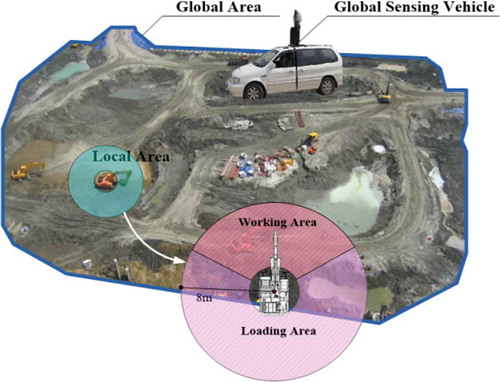
3D surround modeling technology involves using data on the terrain of the local area surrounding the excavator, including the geometry of nearby objects, and then creating 3D representations. 3D surround modeling is ultimately used to create paths for the intelligent excavation robot to carry away earth, load trucks, or avoid obstacles by sensing nearby trucks, people, and obstacles. The object recognition data is then sent to the remote station. The results of 3D surround modeling presented in this study can be used as important information to execute path planning for the boom, arm, and bucket of the intelligent excavation robot. In addition, the results are used to determine the amount of earth that must be excavated by comparing the volumes before and after each excavation operation. The 3D surround modeling results can also be used to develop an excavation quality inspection process to inspect and decide whether the excavation operation at the current location of the platform can be achieved by comparing against 3D design information. In addition, the results of the earthmoving amount calculation process can be used to estimate the amount that must be loaded onto the truck.
If the 3D surround modeling technology is coupled with object recognition technology to recognize loading trucks, obstacles, people, etc., the combined technologies can serve as critical information for setting a travel path and an alternative path for the intelligent excavation robot, which can be used to make emergency stops while avoiding mobile obstacles. Moreover, to develop a collaboration system for coordinating with multiple automated earthmoving systems, including the man-machine interface (MMI) system, an object recognition system is used to reposition the automated machine for collision avoidance and path identification.
2.2. Analysis of 3D surround modeling technology development status
Research on a fully automated excavation robot can be traced back to earlier research on an autonomous loading system (“ALS”), which was conducted by Carnegie Mellon University in 1999. As shown in , Stentz et al. (Citation1999) conducted research on modeling a surrounding workspace in three dimensions by mounting 2-axis laser scanners on both sides of the ALS. In this system, the scanner on the right side performs 3D modeling of the workspace in front of the machine, while the left scanner detects trucks or objects that are approaching the machine, with the horizontal scanning angle for each scanner being 120 degrees. The two 2-axis laser scanners obtained from the ALS research comprise a laser distance measuring sensor fitted with two rotational axes and a reflector, which are basically the same as a 3D laser scanner in terms of structure, that are capable of measuring terrain points at a rate of 12 kHz. As the ALS was designed to recognize a truck using its left laser scanner, it can only perform loading operations when the excavator is located on top of an elevated bench with a truck parked at a designated location, which can be approached from left. In other words, in case where the excavator and the truck are at the same level or the truck is approaching from behind of the excavator platform, the loading operation becomes impossible. Given that excavators exhibit variable working patterns, regardless of the position of the excavator platform, the excavator should be able to perform a proper loading operation.
Figure 2. Autonomous loading system (CMU) (Stentz et al. Citation1999).
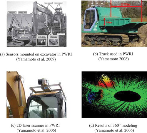
Meanwhile, the autonomous hydraulic excavator (“AHE”) developed by the Public Works Research Institute of Japan (“PWRI”) in 2006, which is shown in , is equipped with GPS, a direction sensor, gyro sensor, and an azimuth sensor with an independent task planning system. The AHE employs a stereo vision camera to enable 3D modeling of the front workspace and used a 2D laser scanner for 360-degree surrounding area modeling (Yamamoto Citation2008). Unlike the ALS, to recognize where a truck is located, the study adopted an approach of equipping the truck with GPS and direction sensors, as illustrated in . Such a system requires high-precision GPS and direction sensors, and the trucks used for testing were quite different from large dump trucks that typically operate on actual earthwork sites. As the truck loading system used by the PWRI of Japan does not involve direct modeling and recognition of the truck, its software configuration can be very simple. The problem, however, is the high costs involved in implementing high-precision sensors and in some scenarios, an estimation of the truck bed area may not be entirely reliable. In fact, for a GPS system that supports errors at the centimeter level, the per-unit cost is more than $8,500. In a solid communication environment, it operates within a margin of error of 1 cm, but when communication with the base is poor, errors of more than 10 cm can occur, indicating that performing a fully automated loading operation is highly likely to result in collision accidents.
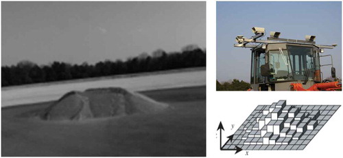
In 2008, the PWRI performed research on 3D modeling of a 360-degree area using a 2D laser scanner. As shown in , a sensor was mounted on top of the cab of the excavator to create a three-dimensional representation of the surrounding terrain by slowly rotating the swing body in a 360 degrees angle. In such a method, to obtain one page of topographic data, an excavator must stop its work and slowly rotate itself at constant speed, and if the rotation speed fluctuates, it is difficult to obtain an even distribution of points (). Another limitation is that 3D modeling based on data from a 2D laser scanner requires a precise horizontal rotation angle, which means that an additional sensor must be installed on the rotational axis of the excavator.
Figure 3. Autonomous hydraulic excavator (PWRI).
Also recently, there have been similar studies in Japan using a 2D laser scanner and stereo vision sensor mounted on top of a wheel loader to detect a dump truck and a pile of soil. In his study, Sarata et al. (Citation2007) used an algorithm that identifies a truck by detecting the ground plane and then a vertical straight line from the ground (). Later Sarata, Koyachi, and Sugawara (Citation2008) conducted research on detecting the location and shape of a pile of soil by measuring the height of the pile from the ground using stereo vision cameras installed on top of a wheel loader (). However, these methods have some limitations as the typical terrain on actual earthwork sites tends to be much more rough and uneven.
Figure 4. Detection of the location of a truck using 2D laser sensor (Sarata et al. Citation2007).
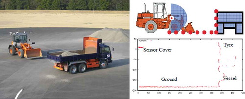
Figure 5. Detection of soil mound using stereo vision (Sarata, Koyachi, and Sugawara Citation2008).
Corke, Roberts, and Winstanley (Citation1999) developed a mining robot equipped with a stereo vision camera and conducted research on 3D modeling of rocks in an underground mine by projecting illumination (). Whiteborn, Debrunner, and Steele (Citation2003) conducted research on building 3D models of underground mining operations by mounting stereo vision equipment and headlights onto an LHD vehicle specifically developed for underground mining operations.
Figure 6. LHD vehicle (Whiteborn, Debrunner, and Steele Citation2003).
2.3. Considerations for 3D surround modeling sensor hardware
To design hardware for a 3D surround modeling sensor, this study analyzes some of the problems of previous research and identified the following considerations:
2.3.1. Minimizing blind spots for the surrounding terrain
In both studies performed by CMU and PWRI, the sensor systems of the fully automated excavation system focus on 3D modeling of the terrain of the work area in front of the excavator. This is because a fully automated excavation system typically travels to its work location and then stops its platform to scan the initial work area terrain after which with each digging operation, the system rescans the terrain to monitor the digging progress. Previously developed automated excavation systems are characterized by terrain modeling sensor systems mounted on the top of the cab facing downward, which is closely related to the shapes of the excavated terrain. As the stereo vision camera system and the laser scanning system are likely to create blind spots, these approaches are considered for minimizing blind spots in the excavated terrain, as much as possible, thereby precisely modeling the changing shape of the terrain after each bucket pass. In particular, when a sensing system is located over the top of the excavated terrain, perpendicular to the ground, blind spots can be minimized and the most even density modeling is made possible. Therefore, a 3D surround modeling sensor system must be located at a level that is as high as possible, pointing downward to allow for sensing of the terrain below.
2.3.2. 3D modeling of the 360° work area around the excavator
CMU’s fully automated excavation system uses a left scanner, among its two 2-axis scanners, to detect a truck, which is supposed to stop at a designated location within the 120 degree sensing range. If the truck is outside of this range, unless the excavator’s swing body rotates, it is impossible to detect the truck bed, let alone identify whether the tuck is anywhere near the excavator. This also has close implications for a possible collision between the excavator and the truck. Given that the excavators exhibit diverse operation patterns, they should be able to promptly and accurately recognize the truck bed from whichever direction the truck approaches within 360 degrees. In the CMU system; however, accurately recognizing the truck bed area requires the excavator to be positioned higher than the truck. Because the truck bed is as high as approximately three meters from the ground, blind spots will be created as the truck is scanned if the truck and excavator stay at the same level, which also means that the truck bed area cannot be fully covered for 3D modeling. In typical earthmoving scenarios, the excavator is often positioned on top of an elevated bench during the earthmoving operations, and the excavator and the truck frequently operate at the same altitude. To address this problem, a sensing system that rotates 360 degrees at constant speed must be designed to be located at a significantly high level from the ground while being closest as possible to the rotational axis of the excavator.
2.3.3. Implementing 3D topographic data-based object (trucks, site personnel, etc.) recognition
Because a fully automated excavation system does not involve any operator throughout the entire operation process, possible collisions with nearby obstacles or objects can be a critical issue. While the CMU research partially experimented with truck and object estimation, there is little research on the object recognition rate and truck bed recognition. In PWRI’s fully automated excavation system research, with its primary focus on 3D modeling of the front workspace, only the truck bed area was subject to estimation using GPS and direction sensors, and none was done on object detection. For an intelligent excavation system to be able to accurately and promptly recognize any obstacles or objects in the excavator’s path, a highly sophisticated object recognition algorithm is required to discern an object from 3D data on the local area in a prompt and accurate manner and to estimate the type of object, including its moving direction. Recognizing objects, such as loading trucks and site personnel, in atypical terrains requires 3D topographic data with significantly even and accurate density, which must be considered while designing the hardware for the 3D surround sensor.
3. Design and development of 3D surround sensor hardware
3.1. Analysis of the optimal location of a 3D surround sensor
Existing research on automated excavation focus on performing 3D modeling of changing workspace terrains and objects around an excavation robot, and most research use a stereo vision camera, 2D laser scanner, or 3D laser scanner as a sensor interface device for 3D modeling and object detection. A stereo vision camera can rapidly acquire video images but it exhibits a considerable amount of noise and its accuracy is very low, which means that the camera can take quite a long time to process the data; whereas a terrestrial 3D laser scanner is expensive and susceptible to vibrations in the external environments, and so modifying the laser scanner to suit the excavation operations can be a challenge. Therefore, in our previous research by Yoo, Kwon, and Kim (Citation2013) we identified five factors–economic feasibility, data acquisition speed and scope, accuracy, ease of installation, durability–and computed the weight for each factor using the analytic hierarchy process (AHP) method to determine the most ideal 3D modelling sensor for an intelligent excavation robot. The resulting weighted preference calculation determined that among a terrestrial 3D laser scanner, 2D laser scanner, stereo vision camera, and structured light sensor, a 2D laser scanner is the best fit for the intelligent excavation robot. Therefore, we use a 2D laser scanner to design hardware for a 3D surround sensor.
As the purpose of the 3D surround sensor of the intelligent excavation robot is to model the 360° area surrounding the excavator, definitions concerning the specifications of the intelligent excavation robot and the working area to be excavated must first be provided. In this research, we used Doosan Infracore’s DX-140LC, an excavator with a height of 2.8 meters, boom and arm length of 4.0 meters and 1.9 meters, respectively, maximum excavation distance of 8.2 meters, and maximum excavation depth of 5.0 meters from the ground.
The ultimate goal of the 3D surround sensor is to recognize and localize trucks or objects that are approaching the excavator, which requires an analysis of where the excavation system and the loading truck are located. In earthmoving operations, excavation (cutting) involves either piling up soil near the platform or loading it onto a truck that is in proximity of the platform. This means that the cutting area and the banking area typically exist independently of one another. Similarly, in the case of banking, the same applies to the loading area, but it is preferable for the excavator to be positioned at a higher location compared to the truck during the loading operation because this offers an unobstructed view to an operator of the rectangular loading area, minimizing potential accidents where the excavator’s arm or bucket might collide with the truck bed area. However, in actual earthwork sites, loading formation may be flexible depending on the condition of the terrain of the construction site, while in drainage construction, the truck and the excavator often operate at the same altitude. Therefore, a truck must be allowed to approach in whatever direction possible within 360 degrees from the rotational axis of the excavator. In addition, with or without an elevated bench, the three-dimensional coordinates of the truck bead area can be accurately recognized.
Because the 3D surround sensor of the intelligent excavation robot must model an area 360° around the excavator, the closer it is located to the center of the excavator on the XY plane, the better it is to evenly model the entire area, as illustrated in . In actual scenarios, aside from the excavation work area (30°-150°) around the center of the excavator platform, a truck can enter the remaining area (151°-360°) from any direction, and in some cases, a truck might even enter the front work area. Therefore, the area within 7.5 meters from the excavator’s rotational center must be set as a loadable area. Moreover, to predict whether a truck or object is approaching the excavation system, the look-ahead distance for determining whether anything is approaching should be 15 meters from the excavator’s center.
Meanwhile, the 3D surround sensor of the intelligent excavation robot creates blind spots, as shown in , no matter where the sensor is positioned because of the shape of the excavator itself. To minimize such blind spots, the sensor must be located as high as possible while also remaining close to the excavator’s central axis. illustrates the blind spots that can be created when the sensor is located at 4.7 meters above the ground, with the front blind space being 1.8 meters and the rear being 0.95 meters. To even out the front and rear blind space, it might be better to position the sensor at the center of the rotational axis or slightly to the right, but if the sensor is mounted on top of the cab, problems might arise while the vehicle is in motion. Moreover, collisions with the boom or even bigger blind spots caused by the boom are all possible concerns. Therefore, we decided that the optimal location of the sensor should be slightly to the left from the excavator’s central axis. illustrates the blind spots created by the sensor when viewed from the rear of the excavator because the cab is positioned on the left side. The sensor in the figure should be located slightly to the right from the rotational axis of the excavator to minimize the blind space on the left and right sides. As shown below, with the sensor positioned at 4.7 m above the ground, slightly to the left from the excavator’s central axis, the left and right blind spots are 1.15 m and 0.98 m, respectively.
Figure 7. Loading sensing area and blind spots caused by loading sensing area and sensor location.
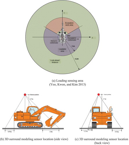
In conclusion, if the sensor is positioned closer to the excavator’s central axis, the blind spots created by the excavator will be minimized and most evenly distributed, and given the height of the truck (3m), the higher the sensor is positioned above the ground, the more it can scan the truck bed, thereby minimizing the blind spot for the truck bed. However, to determine the sensor’s height, mobility of the intelligent excavation robot must be considered. In addition, the fact that as the sensor gets higher, the impact caused by vibrations can become even greater. In this research, we considered the height of the cab, the amount of blind spots that can be created by the cab and boom and finally determined the back part of the excavator’s cab to be the optimal location for the sensor. We also designed the sensor such that it can be positioned at 4.7 meters above the ground.
3.2. 3D surround sensor layout design
The 2D laser scanner (LMS-151, SICK) used for terrain modeling in our prior research on intelligent excavation robots exhibits a sensing range of 270° around the Z-axis, as shown in , measuring 27,050 points per second with an angular resolution of 0.5°. The 2D laser scanner scans 270° on the XY plane at a rate of 50 Hz with one scan measuring 541 points with an angular resolution of 0.5°. A 2D laser scanner, unlike a 3D laser sensor with two rotational axes, is a one-axis sensor. This means that acquiring 3D geometric data using a 2D laser scanner must involve either the sensor moving horizontally at constant speed or rotating around either the X-axis or the Y-axis. In this study, as shown in , we set up the Y-axis of the 2D laser sensor such that it is positioned vertically downward while simultaneously directly rotating the Y-axis. This allows the sensor to simultaneously scan the right and left sides of the intelligent excavation robot, making it two times faster to create a 3D model of the full 360° workspace.
Figure 8. 2D laser scanner orientation.
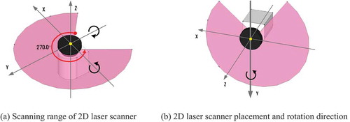
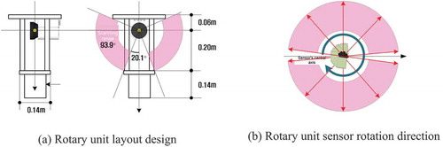
As such, to rotate the Y-axis of the 2D laser sensor while positioning it vertically pointing downward, the sensor’s rotary component design should be such that the Y-axis of the sensor coincides with the rotational axis of the instrument and there should be no blind spots caused by the rotary unit within the sensor’s scanning range. In other words, because the sensor attached to the rotary unit must have a field of view of 20.1° on the right and left sides of the Y-axis, the total height of the rotary unit should be at least 0.4 m, as shown in , assuming that the width and length of the driving part of the rotary unit are 0.14 m each. Such a layout allows the 2D laser scanner of the rotary unit to exhibit a 93.9° scanning range on each side. Using a start signal for the automated excavation operation, the 3D surround sensor of the intelligent excavation robot simultaneously begins to sense the surrounding 360° area and continuous to operate while the excavation robot performs the operation. In addition, as the sensor continuously scans the surrounding 360° area in one direction, slip rings must be used, and because the sensor scans both the right and left sides of the vehicle, the 0–180° area and the 180–360° area must be segmented and processed separately in the data processing stage.
Figure 9. Rotary unit layout and rotation direction.
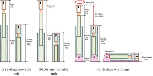
As discussed previously, the 3D surround sensor should be located at 4.7 m above the ground to be able to model the entire area around the intelligent excavation robot. If the sensor is designed to be fixed like a tower, it can cause some problems when the excavation robot goes off the earthwork site to another location. Given the fact that a typical Caterpillar-type excavator is loaded onto a truck for relocation as it cannot be driven on the highways, the maximum overall height, including the height of the truck bed, must not exceed 4.2 m, which is the maximum limit for highways. Therefore, the top rotary unit of the sensor should be designed to enable an up-and-down motion, with the height of the sensor top in the most reduced (the lowest) state of 2.7 m tall or less above the ground. As the back part of the cab of the intelligent excavation robot is actually 2.0 m tall, the height of the fixed-type sensor should be less than 0.7 m. Assuming that the sensor’s Y-axis coincides with the central rotational axis; its rotary unit is 0.4 m high; and the total instrument height is 2.7 m, as shown in . A 2-stage movable unit is estimated to be as long as 1.55 m in the most reduced state, and a 3-stage movable unit to be as long as 1.16 me, as shown in . In conclusion, with the rotary unit being at least 0.4 m high, regardless of the extent to which the minimum height is reduced by adding more stages, you cannot satisfy the 0.7 m limit. To address this limitation, we have devised a way to add a hinge and clamp mechanism at the bottom of the instrument to be able to rotate the instrument. With these additional hinges at the bottom of the instrument, the intelligent excavation robot will be able to travel for long distances in a folded position free of the height limit as the instrument’s maximum height will then be 0.4 m and the overall height from the ground will be 2.4 m.
Figure 10. Sensor movable unit layout design.
Another important consideration in the layout design stage is the average horizontal rotation speed of the sensor. In 3D modeling of the local area, there is a trade-off between rotation speed and modeling quality (point density). While a slow rotation speed of the 3D surround sensor does not directly affect the time the intelligent excavation robot executes its operation, it can have implications for a 3D modeling data-based object recognition process as the process is triggered only when the sensor’s rotational axis passes the 0° and 180° points, meaning the sensor’s rotation speed equals the speed of the object recognition results being updated. In addition, if the automated excavation process includes a loading operation, the intelligent excavation robot will wait at a designated location until it senses a truck and detects the vertexes of the truck bed, and the slower the detection process, the more delay it will incur in the excavation work process. On the other hand, if the horizontal rotation speed of the 3D surround sensor is too fast, the number of three-dimensional terrain and object points retrieved will be reduced, which then leads to lower quality terrain models, ultimately degrading the performance of the object recognition process. Therefore, the optimal rotation speed of the 3D surround modeling sensor should be set at a level that does not undermine the performance of the object recognition process, and from the results of several tests, we determined that approximately 60° per second is the most effective speed.
3.3. Detailed design of a 3D surround sensor
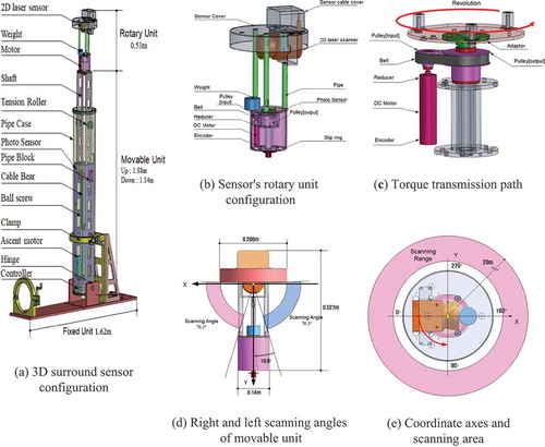
Based on the sensor layout design discussed in the previous section, we used SolidWorks 2008 to create a detailed design of the 3D surround sensor. As shown in , the 3D surround sensor comprises a rotary unit, movable unit, and fixed unit, with the overall height being 2.71 m when fully stretched and 1.82 m when reduced the most.
The sensor’s rotary unit, as shown in , essentially uses a DC motor, reducer, encoder, and controller, and input and output pulleys and a belt are used to drive the rotating shaft. Similar to our previous discussion, as the Y-axis points downward, the smaller the size of the rotary driving part, the greater is the scanning coverage that can be achieved. In terms of size, the rotary driving part can benefit from a smaller motor with low starting current and high speed. In this research, we used an EC-max22 283,840 DC motor (12W), and as a reducer for the motor, a φ22 mm planetary gear (GP22C 144,003, 690:1) was used. An incremental encoder that issues 128 pulses per revolution was used. Given that the motor’s gear reduction ratio is 690:1; a reduction ratio driven by belt and pulleys is 34:18; and the number of encoder pulses per revolution is 128, the number of pulses that the sensing instrument outputs per revolution is 166,827, with the resulting resolution per pulse at 0.002°. As shown in , the final power realized through the motor and reducer is transmitted to the rotational axis with a reduction ratio of 34:18, thereby rotating the 2D laser scanning sensor around the pipe shaft.
illustrates the manner in which blind spots can be created by the rotary driving part of the 2D laser sensor, and in detailed design, we secured a field of view of 16.8° by increasing the length of the pipe shaft. As the surround modeling sensor is located at 4.71 m above the ground, the angle above the x-axis of the 2D laser sensor is barely scanned, and so we placed a sensor cover on top of the x-axis. The resulting scanning angle for the 2D laser sensor is 76.1° on the left and right sides. To control the rotation position (angle) of the 3D surround sensor, an EPOS 24/1 controller (Maxon) was used, and the rotation speed was designed to be controlled in four different modes (8.3 rpm, 7.5 rpm, 5.0 rpm, 3.75 rpm) As the 3D surround sensor employs an incremental encoder, an index signal must be entered to calculate the current horizontal angle of the sensor instrument. As shown in , an index signal was designed to be issued when the sensor passes the – X-axis plane. The 3D surround sensor has been designed to infinitely rotate counterclockwise and scan up to 20 meters ahead until it receives a stop signal.
Figure 11. Detailed design of 3D surround sensor.
As shown in , the movable unit of the 3D surround sensor is designed such that it is 2-tiered and its top sensor part can move up and down, driven by a DC motor and a ball screw. As the motor used for the movable unit only produces an up-and-down movement, it does not control the position and consists of a motor, reducer, and brake. As for the DC motor, we chose a 60w, large torque model (EC-max30 272,763) as the motor must withstand the weight of the sensor’s rotary unit, upper shaft, base, ball screw, linear bushes, etc. As a reducer for the motor, a φ42mm planetary gear (Maxon GP42C 203,115, 12:1) was adopted. In this research, the ball screw is used as the primary power transmission device and as shown in , the power from the motor is transmitted to the ball screw rod through the input and output pulleys and belt, and based on the rotating direction of the ball screw, the upper base fitted with the ball screw nut moves up and down. The upper base exhibits an up-and-down movement until the index sensor signals are received, and in case if there is any problem with the index sensor signals, the design includes urethane buffers at the top and bottom of the lower base. To protect against vibrations, the upper and lower bases each have two shafts and linear bushes, and an amplifier was installed onto a circular plate at the bottom of the lower base.
Figure 12. 3D detailed design of 3D surround sensor movable unit.
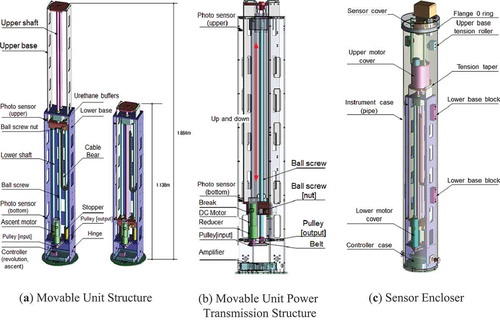
As the 3D surround sensor stands as high as 4.7 m above the ground with a 2D laser sensor on its top, it can be greatly affected by vibrations from the excavator. In this study, we installed a base block between the lower base and the instrument case to securely fix the lower base, and by installing a tension roller onto the upper base, we ensure that tension can be imposed even when the instrument is fully stretched. In addition, because excavation operations are susceptible to dust, humidity, and rain, we put in place an enclosure, as shown in , to completely block the instrument from rain or dust in a fully stretched state.
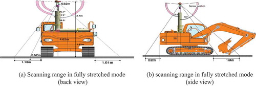
As illustrated in , we reviewed the scanning range and the angles of blind spots when the 3D surround sensor is mounted on the intelligent excavation robot. When viewed from the rear of the excavator, the sensing instrument is 4.7 m tall, and based on the Z-axis the minimum blind spot is measured at 17.2° while the maximum at 34.6°, and with the blind spot of the rotary unit on the Z-axis designed to be 16.8°, there will be no blind spot caused by the instrument. The maximum non-modeling region because of the shape of the excavator is 1.13 m on the left and 1.01 m on the right. When viewed from the side, the minimum blind spot is 30.3° based on the Z-axis while the maximum is 45.0°, and the maximum non-modeling region is 0.92 m in the rear and 1.64 m in the front.
Figure 13. Scanning range of 3D surround sensor.
4. 3D surround modeling system assembly and field test
4.1. 3D surround sensor hardware assembly and installation
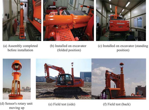
In this study, we developed the hardware for a 3D surround sensor in the following order: materials processing, trial assembly, surface treatment, and final assembly. Each component of the 3D surround sensor that was designed using the SolidWorks software in the detailed design phase was built of duralumin 7075 and precisely cut, and as shown in , a trial assembly was performed to verify the design of the instrument and to ensure that all parts fit together properly. Moreover at this stage, control cables for the 2D laser sensor and the sensing instrument were put in place to verify that the instrument moves properly and that sensor data is well received. Following the pre-assembly test, parts that must be exposed externally were painted in the same color as the excavator and the surfaces of internal parts were anodized. illustrates the sensing instrument installed on the intelligent excavation robot after all surface-processed components were finally put together on site. The 3D surround sensing system hardware was installed on the rear part of the cab, and for the following six months, several tests were performed to verify terrain data acquisition, object recognition, and truck localization on an actual earthmoving site.
Figure 14. 3D surround sensor trial assembly test.
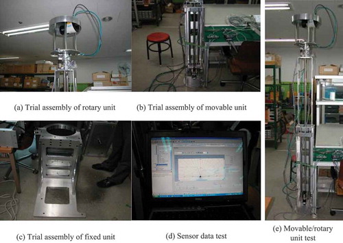
Figure 15. Final assembly of 3D surround sensor and field test.
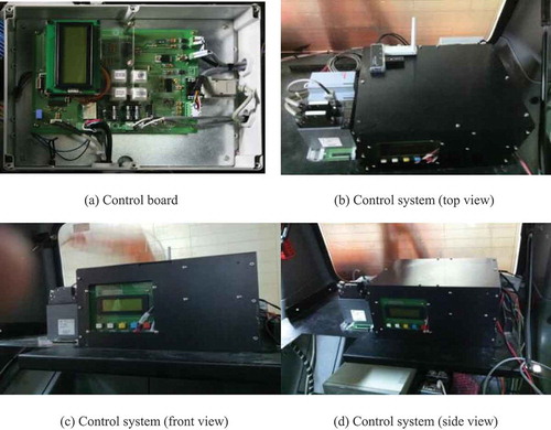
The control system of the 3D surround sensor is intended to control the motion of the sensor instrument, process 2D laser sensor data in real-time, and transmit sensing results to the remote station. Therefore, the control system is essentially responsible for controls of the sensor instrument, sensor data processing, results transmission, etc. In this research, we built a control board for controlling the instrument as shown in , and the enclosure for the control system, which is made of duralumin, was anodized. The control system was placed on a shelf affixed with brackets in the back of the cab, along with an encoder pulse counter to its right side for transmitting the motor’s rotation angles to the data processing board.
Figure 16. Local sensor control system installed.
4.2. Field test of the 3D surround sensor
The data processing software for the 3D surround sensor proposed in this research was developed using Microsoft Visual C++ 2010 as a Window 32-based application software (). The software is based on OpenGL, an open library, and allows the user to simultaneously view the data processing results and the sensor’s controls of the instrument.
Figure 17. User interface for a 3D surround modeling module.
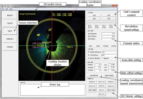
The 3D surround modeling software runs on the control system () installed inside the cab of the intelligent excavation robot, and it has been designed such that the same screen can be displayed on the monitor at the remote station via wireless TCP/IP data communication. All modules of the 3D surround modeling software have been designed to operate in a fully automatic manner except for some initial default values.
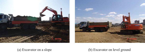
As illustrated in , the field test on the 3D surround sensor was focused on verifying that the sensor can accurately create three-dimensional models of the loading truck, including the truck bed area in the same environment as an actual earthwork site. The test was performed assuming various scenarios that can occur on site without deliberately controlling any surrounding objects such as piles of earth, vehicles, people, etc. at the test site. A dump truck that is used for an actual loading operation was used for the test.
Figure 18. Test environment for loading area recognition.
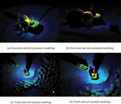
An analysis of the 3D surround modeling data measured at the actual earthwork site demonstrates that 3D surround scanning quality is outstanding without any particular noise detected (). In addition, the shapes of people or trucks were captured clearly, which indicates no significant impact from the vibrations that might have been caused by the excavator. We also analyzed the accuracy of the 3D modeling results using a total station, and the results exhibit an average error of 3 mm within a 20-meter range (Yoo, Kwon, and Kim Citation2013). If the rotation speed of the sensor is increased, the scanning time for the front workspace can be reduced, while simultaneously exhibiting lower point density. A slower rotation speed, on the other hand, can translate into higher-density geometric data, but the scanning time per rotation becomes longer. Overall, the test results demonstrated that the ideal rotation speed should be set at three seconds per rotation.
Figure 19. Results of a 3D surround sensor’s local area modeling.
The primary purpose of this paper is to design hardware for a sensor system and enable the creation of a high-quality 3D terrain map in a prompt and accurate manner with the minimum blind space. Identifying the location of a truck or site staff surrounding the excavator based on 3D terrain modeling will be addressed in subsequent work. Therefore, the primary focus of this paper is placed on verifying the accuracy of the sensing system proposed.
To test the accuracy of the sensing system developed, we first set up 9 circular targets in the terrain surrounding the excavator and obtained 3D data by rotating the sensor mounted on the back of the cab at constant speed, and then using the software developed in this study constructed a 3D terrain model. Afterwards, we measured the distances between the sensor’s origin and the 9 targets with a total station, a laser surveying instrument used in civil engineering and earthworks, and calculated errors by comparing the physical distances with the computed distances in the 3D terrain model (). The same test was conducted twice, so a total of 18 distances were compared (). The test found that the average error was 0.003 m (SD = 0.0082 m) and the maximum was 0.023m, indicating its accuracy is comparatively superior to that of a stereo vision camera. It was also found that, as was the case for a stereo vision camera, the longer the distance is from the 2D laser scanner to the target the greater the error becomes with the magnitude of the error being proportional to the distance.
Figure 20. 2D Laser scanner based 3D terrain modeling.
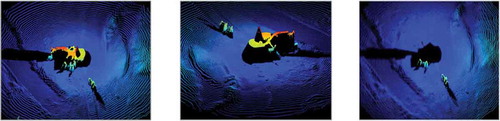
Table 1. A: calculated distance at 3D model, B: actual distance measured by total station.
5. Conclusions
In this paper, we developed hardware for the 3D surround sensing system to construct 3D models of the 360° workspace surrounding the intelligent excavation robot. We conducted tests to create such three-dimensional models of the terrains and obstacles on an actual earthwork site. The conclusions that we arrived at are as follows:
From our analysis of the optimal location of the 3D surround sensor, we determined that the sensor should be located on the right of the rotational axis of the excavator to minimize blind spots on the right and left sides of the sensor, with the most appropriate place being on top of the air compressor inlet on the back of the cab. In addition, given the blind spots caused by the height of the loading truck and the shape of the excavator, the sensor must be located at least up to 4.7 m above the ground.
Upon analyzing the direction in which the 2D laser sensor must be installed and rotated, we determined that to allow for easy control of constant speed and data processing, the 3D surround sensor should infinitely rotate at 360° in one direction, with a rotation speed of 30–40 degrees per second. In addition, the Y-axis of the sensor should be perpendicular to the ground and coincide with the horizontal rotational axis, which is the most effective way of simultaneously scanning the right and left sides of the sensor.
We designed a hardware layout for the 3D surround sensor, which comprises a rotary unit, movable unit, and fixed unit. Our analysis demonstrated that the rotary unit should be at least 0.4 m in height to gain a scanning angle of 20.1 degrees around the rotational axis during its one-direction, infinite rotation movement. The rotary unit used a DC motor as its power source, along with the belt and pulleys for power transmission to drive the rotating shaft. As for the movable unit, a ball screw was used to enable the up-and-down movement while the belt and pulleys were utilized to transmit power for the ball screw.
We developed a Windows 32-based 3D surround modeling software to process data from the 3D surround sensor. Field tests were conducted at an actual earthwork site with the results exhibiting outstanding 3D scanning quality for the 360° workspace and zero noise. In addition, the resulting images clearly exhibit the shapes of people and other objects like trucks such that there is no significant impact caused by vibrations from the excavator.
The 3D surround sensor and 3D terrain modeling technology presented in this paper can be used for a system that detects and recognizes objects approaching the intelligent excavation robot from any direction within 360 degrees, and when compared with the previous technologies by Stentz et al. (Citation1999), Yamamoto (Citation2008), Yamamoto et al. (Citation2006), Yamamoto et al. (Citation2009) of unmanned excavators it is considered to be the most advanced technology in terms of its expanded sensing range, reduced blind spots, and finer modeling resolution due to improved precision. The technology can be further developed to be used for planning travel paths for the intelligent excavation robot; avoiding people and preventing potential collisions; determining whether to stop work or not; and recognizing the truck bed area of a truck. If the sensor’s performance is further enhanced with continuous research and development efforts based on the results of this study, it should contribute to developing a new sensor not only for the intelligent excavation robot, but also for other types of unmanned earthmoving machines. We expect that this technology can be used for many other types of automated construction and earthmoving equipment and will have wide applications to automated construction equipment going forward.
Disclosure statement
No potential conflict of interest was reported by the authors.
Additional information
Funding
Notes on contributors
Dong-Jun Yeom
Dong-Jun Yeom who earned his Ph.D. in Construction Management in Department of Architectural Engineering in 2018 from Inha University. He has given a series of lectures on computer aided design, computer programming for engineering application, construction IT and etc.at Inha University since 2015. He currently serves as a postdoctoral research engineer in Industrial Science and Technology Research Institute at Inha University.
Hyun-Seok Yoo
Hyun-Seok Yoo who earned his Ph.D. in Construction Management in Department of Architectural Engineering in 2012 from Inha University. He currently serves as a vice professor in Department Technology Education at Korea National University of Education. His research interests are int the area of construction information technologies, automation in construction and etc. He has conducted various research projects in terms of automation in construction: an Automated Pavement Crack Sealing Machine, an Intelligent Excavating System and various applications of information technologies and automation in construction.
Young-Suk Kim
Young-Suk Kim earned his Ph.D. in Construction Engineering and Project Management in 1997 from the University of Texas at Austin. He has given a series of lectures on an execution of building work, construction management, time management, cost management, contract management, construction information technology, and automation in construction and etc. at Inha University since 1999. He currently serves as a professor in Department of Architectural Engineering at Inha University and a chairman of University Development Commission at Korea Institute of Construction Engineering and Management. His research interests are in the areas of sustainable construction, cost and time management, engineering education, and automation in construction. He has conducted various research projects in terms of automation in construction: an Automated Pavement Crack Sealing Machine, Tele-operated Concrete Pipe Laying Manipulator in the Trenches, Automated Controller for Checking Verticality and Automated, an Intelligent Excavating System, and etc.
References
- Cannon, H. 1999. “Extended Earthmoving with an Autonomous Excavator.” Master’s Thesis, Carnegie Mellon University, Pittsburgh, U.S.A.
- Corke, P., J. Roberts, and G. Winstanley. 1999. “3D Perception for Mining Robotics.” paper presented at the annual meeting for society of the Field and Service Robotics, Pittsburgh, U.S.A.
- Sarata, S., N. Koyachi, H. Kuniyoshi, T. Tsubouchi, and K. Sugawara. 2007. “Detection of Dump Truck for Loading Operation by Loader.” paper presented at the annual meeting for society of the ISARC, Kochi, India.
- Sarata, S., N. Koyachi, and K. Sugawara. 2008. “Measuring and Update of Shape of Pile for Loading Operation by Wheel Loader.” paper presented at the annual meeting for society of the ISARC, Vilnius, Lithuania.
- Seo, J., C. Park, and D. Jang. 2007. “Development of Intelligent Excavating System – Introduction of Research Center.” paper presented at the annual meeting for society of the KICEM, Busan, Korea.
- Singh, S., and R. Simmons. 1992. “Task Planning for Robotic Excavation.” paper presented at the annual meeting for society of the IEEE/RSJ International Conference on Intelligent Robots and Systems, Raleigh, U.S.A, August.
- Stentz, A., J. Bares, S. Singh, and P. Rowe. 1999. “A Robotic Excavator for Autonomous Truck Loading.” Journal Autonomous Robots 7 (22): 175–186. doi:10.1023/A:1008914201877.
- Whiteborn, M., C. Debrunner, and J. Steele. 2003. “Stereo Vision in LHD Automation.” IEEE Transactions on Industry Apllications 39 (1): 21–29. doi:10.1109/TIA.2002.807245.
- Yamamoto, H. 2006. “Introduction to the General Technology Development Project: Research and Development of advanced Execution Technology by Remote Control Robot and Information Technology„. paper presented at the annual meeting for society of the ISARC, Tokyo, Japan.
- Yamamoto, H. 2008. “Research on Automatic Control Technology of Excavation Work by Hydraulic Shovel.” Public Works Research Institute. https://www.pwri.go.jp/jpn/results/report/report-project/2007/pdf/2007-sen-3.pdf
- Yamamoto, H., M. Moteki, H. Shao, T. Ootuki, H. Kanazawa, and Y. Tanaka. 2009. “Basic Technology toward Autonomous Hydraulic Excavator.” paper presented at the annual meeting for society of the ISARC, Austin, U.S.A.
- Yamamoto, H., Y. Ishimatsu, S. Ageishi, N. Ikeda, K. Endo, M. Masuda, M. Uchida, and H. Yamaguchi. 2006. “Example of Experimental Use of 3D Measurement System for Construction Robot Based on Component Design Concept.” paper presented at the annual meeting for society of the ISARC, Tokyo, Japan.
- Yoo, H., S. Kwon, and Y. Kim. 2013. “A Study on the Selection and Applicability Analysis of 3D Terrain Modeling Sensor for Intelligent Excavation Robot.” Journal of the Korean Society of Civil Engineers 33 (6): 2551–2562. doi:10.12652/Ksce.2013.33.6.2551.