
 ?Mathematical formulae have been encoded as MathML and are displayed in this HTML version using MathJax in order to improve their display. Uncheck the box to turn MathJax off. This feature requires Javascript. Click on a formula to zoom.
ABSTRACT
The number of building-information modeling (BIM)-applied construction projects has been increased with an expectation that it will transform the labor-intensive building industry into a knowledge-based one. The time and effort required for modeling vary depending on the type of work, and therefore most BIM applications focus on certain work trade of high effectiveness. In this study, we propose a quasi-automated BIM methodology that can shorten the requisite time for modeling regardless of the type of work. The method automatically generates an object-oriented BIM model based on drawing recognition and line-text extraction. To evaluate the proposed procedure, two experiments were conducted. The results show that the method attains a high accuracy in correctly defining a structural building type, and confirm completed object modeling. The proposed modeling process is expected to significantly reduce the required efforts for BIM data generation in practice, and further provide a method of knowledge utilization in the construction industry.
Graphical abstract
1. Introduction
Building-information modeling (BIM), which first appeared as a form of 3D computer-aided design (CAD) in 1990, has been applied to building projects since 2007 with improvements in computer performance (Hardin and McCool Citation2015). Since then, the application of BIM has been extended into the construction field, and as of 2018, some countries, such as Korea, Singapore, Hong Kong, and Australia, have even mandated the use of BIM in construction projects (Mao Citation2017).
BIM is a semantics-based and object-oriented approach, its application allows users to accumulate project information gradually, and use it continuously throughout the project lifecycle for various purposes (Jung and Kim Citation2016; Succar Citation2009; Eastman et al. Citation2008).
However, despite the benefits of applying this technology, the result of a survey in 2017 shows that more than 40% of construction engineering companies still rely on 2D CAD drawings as a medium for project design data storage (Citationjbknowledge, Annual Construction Technology Report). Therefore, to meet the national construction standards, design information recorded in the form of 2D drawings must be converted into 3D BIM data through manual modeling based on the drawings. According to experts, when a BIM model for construction projects is assumed to have the level of detail (LOD) as detailed as required for 4D simulation (Boton, Jubicki, and Halin Citation2015), the time required to develop the model is about 5% of the total construction period. As projects in the construction industry repeatedly suffer from delays and cost overruns (Enxhassi, Al-Narras, and Kumaraswamy Citation2009), this time-consuming and repetitive data-writing task may result in delays in the commencement of construction.
These problems of repetition and the excessive time can be addressed by developing a method for the automatic generation of BIM data using the created 2D drawings. Some researchers suggested creating 3D shape data such as wall and room space, through drawing and pattern recognitions (Gimenez et al. Citation2016; Kim et al. Citation2009; Lu et al. Citation2005), whereas others focused on the acquisition of attributes of quantity information including area through the automated generation of a simple model (Lawrence et al. Citation2014). However, these studies commonly focused on one aspect of BIM-based-form creation or property acquisition- and therefore, the utilization of the created data in a construction project is limited.
In recent studies facilitating object modeling with properties, the method of drawing recognition followed by data generation is limited to specific works (Janssen, Chen, and Mohanty Citation2016; Changsoft and Kim Citation2015); therefore, an automated BIM that could be used for all work trades remained unsolved.
Thus, this research aims to develop a framework for the automatic generation of a 3D object model based on drawing recognition and text-line extraction. By identifying design drawings that are a combination of line and text, and extracting them into separate layers, an object model is created. Specifically, the line information can be used as the planar shape of an object; the knowledge in the text can be employed as its attributes such as its building components. The framework includes the description of the overall process to create an object model through drawing recognition and technical definition at each stage.
Creating a 3D object based on the shape feature and acquisition of attribute information enables BIM data creation regardless of the type of construction work or the status of design development. This distinguishing feature of the method is expected to assist construction managers by reducing the time and efforts needed for model preparation; it further contributes to improve efficiency and effectiveness of construction project management.
To develop this framework, we describe a detailed process of generating an object-oriented 3D model using the extracted information by recognizing and, storing the information separately as line and text, and then creating an object model. By reviewing a wide spectrum of related technologies to generate a BIM model, we identified techniques applicable to the framework and highlights their strengths and potential synergies. Our research differs from related literature in the sense that different technologies from different fields were combined and investigated in this study, and new techniques are suggested.
The remainder of this paper is structured as follows. Section 2 describes related works on automatic 3D as-planned modeling and knowledge extraction through drawing recognition. Next, based on the researched technologies, we suggest an overall object-model-creation process in Section 3. In Section 4, the proposed framework and technologies are validated through experiments and comparisons with the originally suggested technologies. The potential application of our proposed method and the implication of the obtained results are provided in Section 5. Finally, conclusions are drawn in Section 6.
2. Previous approaches on automated 3D model creation
BIM represents the development and use of computer-generated 3D model in the lifecycle of a building project, and the resulting model is data-rich, object-oriented, and intelligent model, and it can meet the needs and aims of various users (Azhar, Hein, and Sketo Citation2008); the model is created in a parametric manner. Specifically, the building-information model comprises the shape and dimension of an object, the space created based on the relationship between objects, and non-geometric attributes such as material, zoning, and construction order (Gimenez et al. Citation2015).
Automated model generation is based on a prerequisite project-related information exists in the form of drawings or existing building structures, and these can be obtained through data conversion. Many studies on automated model generation have been conducted, and these can be classified based on the basic information: as-planned and as-built model generation approaches.
As-built model generation has attracted considerable research attention with the development of related technologies such as unmanned aerial vehicles (UAV) (CitationGIM International), laser scanners, and point cloud data (Bosche and Haas Citation2008; Brilzkis, Park, and Jog Citation2011; Arayici and Gamito Citation2008). By contrast, with the assumption that the project information in 2D CAD will become outdated, research on as-planned model generation has retained less attention among researchers (Barki et al. Citation2015), and related studies have focused on special technologies or a specific work trade such as reinforced concrete or interior finishing (Kim et al. Citation2009; Changsoft and Kim Citation2015). As mentioned earlier, however, the use of project information in 2D drawing remains popular, and it must be prioritized to create as-built models.
This chapter reviews the previous research on automated as-planned model creation and the existing approaches to drawing recognition and knowledge extraction ().
Figure 1. Process of converting 2D drawing into a BIM model
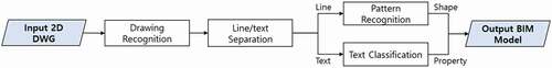
Table 1. Existing approaches of knowledge-extraction and automated as-planned model generation based on drawings
2.1. Extraction and separation of knowledge from recognized drawings
Before the modeling process, project-related knowledge from digitalized 2D drawings, such as DWG or PDF, must be extracted as the drawings contain construction project information such as line and text data. Geometric patterns from lines are acquired for understanding the object shape, and the attributes from texts are necessary to identify the object’s material, element type, and locational information. Because both data are required to complete the 3D shape of an object with properties, the process of distinguishing them as separated layers takes priority and a modeling process is employed (Lu et al. Citation2005, Citation2008).
Fletcher and Katsuri (Citation1988) are well known for a suggesting text and line extraction by using heuristic rules to separate data in one image (Hoang and Tabbone Citation2010). This method is widely used owing to its simplicity and scalability. Nevertheless, the application of this method is difficult when the line and text overlap or touch each other. To complement this method and employ it for graphic-rich images, such as engineering drawings, Tombre et al. (Citation2002) proposed an extraction method that finds a text string’s direction and its boundary box simultaneously.
The morphological component analysis, suggested by Hoang and Tabbone (Citation2010) and Pan et al. (Citation2007), uses a distinguished feature between the text and line to separate them. Zhang and Lu (Citation2004) confirmed the shape-representation and description techniques using generic Fourier descriptor; these became the most effective solution among general image-analysis methods.
After knowledge extraction from a 2D drawing set, a BIM model can be created by linking the obtained information to a basic object model.
2.2. Automated as-planned 3D modeling
Kim et al. (Citation2009) proposed the use of pattern recognition for structural wall modeling. He suggested creating a surface based on line data first, and then creating a complete 3D solid model by surrounding all sides with surfaces. From the resulting model, the exact numeric values of the length, area, and volume of a modeled object could be calculated. Another researcher pointed out that this method of quantity take-off (QTO) addresses the weakness of the conventional method of calculating the values based on the 2D drawings (Lawrence et al. Citation2014). However, this surface model neither contains attributes nor has object-oriented features, and therefore, is limited in its practical use.
In (Changsoft and Kim Citation2015), the authors suggested a commercialized software that supports automatic object modeling using drawing recognition. By using this technology, project location information can be defined and saved, and the reinforcement model is automatically generated after being recognized from the rebar placement drawing. Although this solution implements drawing recognition and subsequent automatic modeling, it focuses on a specific type of work trade.
The aforementioned studies focused on different objectives: (1) distinguishing line and text information when they are mixed in one image, and (2) creating 3D models automatically based on the extracted line data from drawings. However, to apply these methods in real construction projects, these technologies must be integrated under one framework to ensure a continuous workflow.
Ahmend et al. (Citation2011) and Gimenez et al. (Citation2015) proposed methods that separate geometric elements and textual information through text/graphics segmentation and generate a 3D wall model and an enclosed space model surrounded by these elements. However, they focused on wall modeling that constitutes space and not on generating the attributes of the object. Further, their modeling resource was scanned engineering drawing, and therefore, cross-sectional relations, such as ceiling height or level, were not considered.
In summary, several studies have been conducted in various fields on knowledge extraction-separation from images, followed by automated 3D model creation. Some of these studies focused on knowledge extraction and separation of text and line data, while others focused on model generation. Although a few studies proposed the integrated process of drawing recognition and modeling, their range of application was limited in terms of work trade, such as reinforcement, or toward certain building components such as walls. Therefore, a method is needed for automatic BIM based on the digitalized drawing regardless of the type of work.
3. Process overview of automated modeling based on drawing recognition
The overall process for the automated modeling framework based on drawing recognition is described in . Subsequent to an architect’s design data creation, the data are separately extracted using the text/graphic separation techniques. The lines and texts in a drawing provide basic knowledge about a building project in terms of geometric and semantic information. By means of project information recognition, the planar centerlines and the level information, which represent the project location information, are acquired as basic information.
Figure 2. Overall process of conversion from 2D drawings to 3D BIM
The text data adjacent to a polygon, or object’s shape, is passed through a Bayesian filter to identify what building component of the object is to be modeled (see Section 3.2). Then, by mapping the geometric features of the planar size and height to a basic object for modeling defined from the previous step, the shape of object model is completed (see Section 3.3). Finally, the properties of the created object, such as its location, size, and type decided from the modeling process are recorded as a lookup table to use later during construction management.
3.1. Drawing recognition and line-text extraction
First, plan and section drawings are imported to model the exact position. In particular, the precise location of individual elements to be modeled is confirmed by comparing them with the 2D centerlines and the 3D sectional level lines, which are the basic locational information of a project. As geometric and semantic information of each building object used in the design process is described as not only a form of line but as text, the recognition of the structural table should be accompanied.
Next, a process to separate the line and text information from the recognized drawings is employed. As engineering drawings display the design information of the project through lines and text, both data must be recognized and understood. The separation process of these data was originally proposed and developed by Fletcher and Katsuri (Citation1988) as text/graphic separation. With the recent development of the CAD software, these data can now be immediately separated and stored.
The third step of this phase is to recognize the meaning of text in proximity to the shaped object on the drawing. After storing the line and text in separate layers, an indication of that letter must be identified among the building components, such as columns, walls, and slabs, which are also elementary components of the BIM modeler. In other words, the modeling of a basic object, which is a building element, and the recognized shape are connected to create an object with meaning and shape. To this end, we developed a text classifier by using a Bayesian filter based on conditional probabilities.
3.2. Text classification
The Bayesian filter is well known as the most suitable supervised machine-learning mechanism for class-labeled objects (Diab and Hind Citation2017; Rennie et al. Citation2003). The filter is based on Bayes’ theorem, i.e. when P(A) and P(B) are defined as the probabilities of occurrence A and B, respectively, then P(A|B) is the probability that A will occur after B occurs. Similarly, P(B|A) is the possibility that B occurs after the occurrence of A. The relationship among these four probabilities is expressed as follows:
EquationEquation (1)(1)
(1) can be transformed as follows: the probabilities of the combinations of B and A could be a represented as P(A|B) × P(B); similarly, the combination probabilities of A and B can be represented as P(B|A) × P(A).
The Bayesian filter using this theorem has developed as an algorithm called the Naïve Bayes classification. To classify a certain sentence or word into a different category, the classifier must confirm which class among the plurality of categories is more likely to be included. Thus, from Equationequation (1)(1)
(1) , P(A) represents the probability of the entire input of words that is replaced by 1. Then, the probability that B is in a certain category can be represented as
Based on the Bayesian filter, we developed a text classifier. After training the classifier with abbreviations for structural objects, it is possible to determine which elements are represented by the specific abbreviations from the drawings. The training process uses the extracted words from the structure list and the actual name of the structural elements.
The classification training is performed using the character classifier because the “object,” which is the fundamental modeling element of BIM, is based on building components. In this research, the industrial foundation classes (IFC) was used as the classification system. It is developed by the buildingSMART organization (shown in ) and is based on a “project” or “building.” The subcategory includes specific entities such as structural system, architectural system, and opening system; the structural system comprises, beams, columns, slabs, and walls.
Figure 3. Confirming the object’s location with respect to centerlines and level information, and then determining object size and material using the structural table
3.3. Object modeling
3.3.1. Acquisition of project location information
To place objects accurately in the modeling environment based on the project’s origin point, centerlines and level reference lines must be recognized before the modeling step. In this study, the technology from ChangSoft I&I was used; it recognizes a specific drawing layer and loads it as separate information. It then enables a mechanism to import and utilize guidelines and level information as the project’s basic information by importing the relative position from the origin of the drawing (Changsoft and Kim Citation2015). Specifically, we can attain the centerlines and level information from the planar and sectional drawing, respectively.
3.3.2. Planar-sectional geometry mapping
After acquiring the positioning guides, the position, shape, and abbreviations indicating the object are simultaneously identified by dragging the area including the object to be recognized from the floor plan. Pattern recognition is applied to understand an object’s planar shape by grasping the positions of both diagonal end points that determine the size and shape of the rectangle.
In the case of a perpendicular column C1, the object’s lower center point (Pcl), where the structural centerlines intersect the object’s footprint, as well as the top left point (Plt) and a bottom right point (Prb), which is diagonally located end points of polyline at the planar section, must be ascertained (). After acquiring these three points, the geometric information of position, shape, and size can be mapped to a basic column component.
Figure 4. Building classification used in industrial foundation classes (IFC)
The sectional position is also identified from the level reference that was determined in the previous section. In a similar way, a three-dimensional shape creation is finished by identifying the planer center point (Pcl) and the other center point on an upper reference (Pch) of the object, which is the height value for an extraction. To test this process of creating a 3D object model through pattern recognition, an environment was prepared based on the visual studios and conducted experiments in section 4.
Figure 5. Example of extracted points from imported drawings and recognized column, C1. Three points from the plane and two points from sectional plane are determined for mapping the detailed geometry to a basic BIM component
3.4. Property assignment on modeled objects
The property information of the modeled object is saved as a look-up table and used throughout a building’s lifecycle. This attribute is a distinguishing feature of the BIM model compared to other 3D models, and the table is filled in two different ways. (1) It comprises the information obtained from the design phase; this includes design information such as location, size, and material. (2) The table is created after the model is completed, e.g. specific area, and volume of a certain material. Further, manually recorded information, such as construction sequence, zoning, and the person in charge, is included.
4. Implementation and validation of 3D model creation
4.1. Design of experiments and environments
To evaluate and validate our framework, we designed imaginary objects based on an existing structural element list. Two experimental environments were developed separately: one to test the text classification and other to create the 3D shape of an object. In this evaluation, only three building components (column, slab, and wall) were tested.
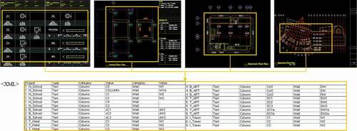
For text classification, the abbreviations of the targeted elements were extracted from four sets of engineering drawings and exported in the XML format (). Before testing these texts, we labeled them to indicate their building element type and then used the labels as a resource for training the classifier.
Figure 6. Extracting process of text data from the structural elements table and conversion to an XML file
Next, text classification and 3D-object-creation modules were developed based on the process and algorithms described in the previous section. Commercial modeling software, ChangSoft I&I, was used for location information acquisition, and Autodesk CAD was used for text extraction process.
The Bayesian filter is developed using Python 3.6 in the Anaconda environment, version 4.6 (). The modeling environment for automatic object creation is built in Microsoft visual studio ().
Table
Figure 7. Building environment and algorithms for the first experimental application of training and testing text classification based on the Bayesian filter
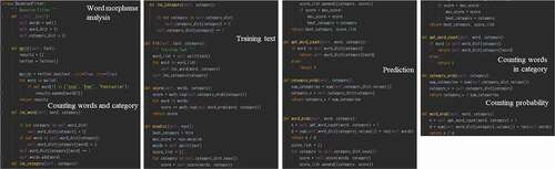
Figure 8. Building environment for the second experiment of automated object generation built in visual studio environment
4.2. Quantitative validation
We applied two metrics for the evaluation and validation of our results. The first metric relies on text-classification validation methods, while the second relies on the accuracy evaluation based on the output of building components’ classes from the text classification and created objects’ geometry, including accurate position and shape.
4.2.1. Classification of extracted text data
The first evaluation process confirmed the classified resulting output of the building component based on the input abbreviation (). Accuracy and error rate are conventional metrics to evaluate a text classifier’s effectiveness (Cai, He, and Han Citation2005). Considering the binary classification question of “yes” or “no,” the model can predict “y” for a true “yes” class; in this case, we call it is a true positive (TP). However, when the correct class is “no,” it is termed as a false positive (FP). In contrast, the model can predict a “no” class as “n,” which is classified as a true negative (TN), and when the class is predicted as “y,” the case is termed as a false negative (FN). This representation of the true class and the classifier’s hypothesis is described in as a confusion matrix.
Figure 9. Confusion matrix for performance evaluation
Table 2. Abbreviations for structural column obtained from four samples of engineering-drawing sets
Based on the aforementioned definition, the accuracy and error rate are defined as
The method of evaluating the data using the accuracy and error rate is a very common method that is not suitable for our research, in which a small data amount is used in the training process. The previous studies on text classifiers used 45–3000 samples per class (Cai, He, and Han Citation2005). In such cases, when the amount of data is small or imbalanced, the F-measure and G-mean, which are comprehensive evaluation methods, can be adopted for model measurement (He and Garcia Citation2009; Tang and He Citation2015).
The F-measure metric combines precision and recall to estimate the classifier’s effectiveness. In particular, when precision and recall have equal weights, the effectiveness is called F1-measure (He and Garcia Citation2009). In addition, the G-mean method explains the sensitivity of the classifier with a positive and negative accuracy.
By considering the amount of data used in this experiment, we applied the macro-F1 score that gives the same weight to each class among the two types of F1-score calculation methods (Yang and Liu Citation1999); the results are shown in .
Table 3. Cross-validation results of the text classifier
4.2.2. Evaluation of building elements
This evaluation of building element is more focused on the output resulting from the classification and following model creation at the building level. As the aim of our research is to provide an automated BIM framework with its environment, this is more compliant with the objective of a BIM model that has geometric and topological information among its attributes.
For this evaluation, we tested the developed and trained text classifier with a new abbreviation, and then monitored the resulting value to identify whether it indicates the building elements correctly. Further, the automatically created object model was evaluated to check whether it is generated precisely in terms of size and location as designed.
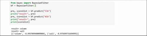
The text-classification result using the Naïve Bayes filter showed a high correct answer rate (). Regarding the abbreviations C1b and W1b, the classifier answered that there is 89.9% probability of the existence of “column” and 89.7% probability of the existence of a “wall.”
Figure 10. Text-classification test results with a new abbreviation input
For automatic modeling evaluation, we manually created an identical model as a baseline for the experiments. A commonly adopted BIM application of Revit with version 2017 was applied. The comparison between the results of our created model and the baseline is illustrated in and .
Figure 11. (a) Designed sample drawing adopted in object modeling tests and (b) a comparison of two generated models: model 1 is from Revit BIM application and model 2 represents our proposed environment
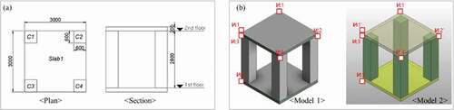
Table 4. Converted coordinates of each model object’s origin
In this paper, the experiment was conducted under the assumption that the building element, which is the result of the text classifier, is brought into the basic object for modeling.
5. Discussion
Our research proposes an automated BIM model generation framework that can shorten the BIM process in construction projects by using 2D drawings-based design information. After confirming the current research status and related technologies, we suggest the process with applicable techniques from drawing recognition and to object-model generation. To evaluate the suggested framework, two kinds of experiments were conducted.
5.1. Performance
In the first experiment, a text classifier based on the Bayesian filter was created. After training this classifier with the extracted data from the drawing, we tested it to correctly identify a new abbreviation. In the second experiment, we performed automated modeling by using line information along with pattern recognition.
The first experiment’s result showed data acquisition and storage without any loss of design data. In addition, the cross-validation results () for the classifying model showed high stability. As the standard score that evaluates a classifier has stable classification performance of 0.8 (Zhang, Wang, and Wang Citation2015), our text classifier, which obtained an F1-score of 0.974 and a G-mean of 0.975, can be determined as stable.
The result of the second experiment (; ) shows a locational deviation compared to the baseline. The comparison between the created models using the basic location and line information of the project with the baseline indicated a total of six mapped objects with the correct size. However, these models differed in terms of their positioning. The relative position of each object was created correctly; however, the object from our developed environment has a position deviation of 31 mm along the x-axis; an identical deviation was observed for all objects. This is considered to be an error in the origin-point recognition.
Thus, further research is required on delivering a project origin precisely. The verification of these experimental results showed that drawing recognition and automatic modeling are expected to achieve significant time reduction compared to the conventional method of manual modeling.
The existing studies regarding automated BIM modeling process focus on the specific rule-set adopted in design phase (Changsoft and Kim Citation2015; Suzuki and Abe Citation1985) or are committed to create a simple solid 3D model so that numerical values are obtained as area and volume (Kim et al. Citation2009; Barki et al. Citation2015) instead of an object-oriented model. Research focusing on the automated object-model creation does not obtain object’s properties such as object’s types or material, which were considered in this study. In contrast to the current applications, this research suggests a method to acquire BIM data through the process of recognizing information based on the completed 2D drawings, and also develops a model that proves the possibilities of the proposed method. This facilitates an automated object modeling regardless of the type of work by using pattern recognition modeling and following attribute assignment process.
5.2. Limitation and future research
This research explores the feasibility of an automatic BIM modeling framework for construction projects when prepared using 2D drawing sets. The authors proposed the process and necessary methods and confirmed the applicability of the methods. The experimental results demonstrated the feasibility of the proposed method. However, the subject of these experiments was confined to few building-structure types, and therefore it is difficult to conclude that all building components could be applied. Further, from the modeling algorithm still has room to include user role, and the process cannot be affirmed as 100% automated. However, this feature is beyond the scope of the present work, wherein the user confirms design information from a drawing set and generates the BIM data manually.
It is also important to use the BIM data generated as much as the BIM model in the construction project. Nevertheless, this research focuses on the process of data-acquisition for model creation and misses the significance of BIM data handling as well as measurement for project application.
Future works should, therefore, include experiments with data quantity including various types and shapes of building elements. In addition, the scope of the study will be expanded through follow-up studies on the utilization of the generated object-oriented BIM data on the construction phases.
6. Conclusions
In the construction industry, the necessity and advantages of BIM application are generally acknowledged. However, workers tend to follow the conventional methods and import project information on 2D drawings. Owing to the mandatory application of the construction project BIM, the process of converting drawing contents into BIM models has become essential. This research was aimed at automating the conversion process to save time and reduce the construction period.
We proposed a framework including the processes of drawing recognition and object modeling. Further, we confirmed the feasibility of our suggestion through experiments and results. We also conducted comparisons using the conventional method applied in automated modeling and machine learning from the computer engineering field.
We expect the results of this study to enrich the existing body of knowledge for project data management in construction projects. Further, we also expect that the development of software based on the current research will improve the time efficiency of construction projects through its practical application.
Acknowledgments
This research was supported by the Institute of Construction and Environmental Engineering at Seoul National University. The authors wish to express their gratitude for the support.
Additional information
Notes on contributors
Juhee Rho
Juhee Rho is a Ph.D. candidate at the Department of Architecture of Seoul National University. She received a bachelor's degree from SNU in 2008. In 2013, she graduated master's course for Architectural Design from University of Pennsylvania. Since 2013, she has started her career as BIM manager in Samsung C&T. Her main research area is construction engineering and management especially in BIM area.
Hyun-Soo Lee
Hyun-Soo Lee received his bachelor's degree in 1983 and master's degree in 1985 at the Department of Architecture of Seoul National University. He has studied Construction Engineering & Management at the University of Michigan since 1988 and finished doctor's degree in 1992. He worked for the Dept. of Architecture Engineering in Inha University as a professor. Since 1997, he has been working as a professor at the department of Architecture and Architectural Engineering of Seoul National University. His major research area is Construction Engineering and Management.
Moonseo Park
Moonseo Park got into Department of Architecture of Seoul National University in 1985, completed the courses for a bachelor's decree in 1989, and graduated master's course for City Planning at SNU in 1992. In 1998-2002, he received master's degree and doctor's degree for Project Management in MIT. After graduation, he worked for the Dept. of Building in National University of Singapore as an assistant professor. Since 2005 he has joined to SNU as a professor at the Department of Architectural Engineering of Seoul National University. Currently, his major research area is systematic approach for construction, knowledge-based construction etc.
References
- Ahmend, S., M. Liwick, M. Weber, and A. Dengel. 2011. “Improved Automatic Analysis of Architectural Floor Plans.” In 11th International Conference on Document Analysis and Recognition, 864–869.
- Arayici, Y., and P. Gamito. 2008. “Modeling 3D Scanned Data to Visualize and Analyze the Built Environment for Regeneration.” Surveying and Built Environment 17 (2): 7–28.
- Azhar, S., M. Hein, and B. Sketo. 2008. “Building Information Modeling (BIM): Benefits, Risks, and Challenges.” Accessed July 2020. http://ascpro0.ascweb.org/archives/cd/2008/paper/CPGT182002008.pdf
- Barki, H., F. Fadli, A. Shaat, P. Boguslawski, and L. Mahdjoubi. 2015. BIM Models Generation from 2D CAD Drawings and 3D Scans: An Analysis of Challenges and Opportunities for AEC Practitioners, In Building Information Modeling (BIM) in Design, Construction and Operations, (Vol 149), 369–380. Southampton, UK: WIT Press.
- Bosche, F., and C. Haas. 2008. “Automated Retrieval of 3D CAD Model Objects in Construction Range Images.” Automation in Construction 17: 499–512. doi:https://doi.org/10.1016/j.autcon.2007.09.001.
- Boton, C., S. Jubicki, and G. Halin. 2015. “4D/BIM Simulation for Pre-construction and Construction Scheduling. Multiple Levels of Development within a Single Case Study.” In Creative Construction Conference, 500–505.
- Brilzkis, I., M. Park, and G. Jog. 2011. “Automated Vision Tracking of Project Related Entities.” Advanced Engineering Informatics 25: 713–724. doi:https://doi.org/10.1016/j.aei.2011.01.003.
- Cai, D., X. He, and J. Han. 2005. “Document Clustering Using Locality Preserving Indexing.” IEEE Transactions on Knowledge and Data Engineering 17 (12, September): 1624–1637. doi:https://doi.org/10.1109/TKDE.2005.198.
- Changsoft, I., and I. C. Kim. 2015. BuilderHub User’s Guide Book v1.0 [Online]. Accessed 16 April 2019. http://chang-soft.com/wp-content/uploads/2015/11/BuilderHub_UsersGuideBook_20151014.pdf
- Diab, D., and K. Hind. 2017. “Using Differential Evolution for Fine Tuning Naïve Bayesian Classifiers and Its Application for Text Classification.” Applied Soft Computing 54: 183–199. doi:https://doi.org/10.1016/j.asoc.2016.12.043.
- Eastman, C., P. Teicholz, R. Sacks, and K. Liston. 2008. BIM Handbook: A Guide to Building Information Modeling for Owners, Managers, Designers, Engineers, and Contractors. Wiley.
- Enxhassi, A., J. Al-Narras, and M. Kumaraswamy. 2009. “Delays and Cost Overruns in the Construction Projects in the GAZA Strip.” Journal of Financial Management of Property and Construction 14 (2): 126–151. doi:https://doi.org/10.1108/13664380910977592.
- “GIM International.” Accessed 1 May 2019. https://www.gim-international.com/content/news/point-clouds-photogrammetry-or-lidar
- Fletcher, L., and R. Kasturi. 1988. “A Robust Algorithm for Text String Separation from Mixed Text/graphics Images.” IEEE Transactions on Pattern Analysis and Machine Intelligence 10 (6): 910–918. doi:https://doi.org/10.1109/34.9112.
- Gimenez, L., J. Hippolyte, S. Robert, and F. Suard. 2015. “Review: Reconstruction of 3D Building Information Models from 2D Scanned Plans.” Journal of Building Engineering 2: 24–35. doi:https://doi.org/10.1016/j.jobe.2015.04.002.
- Gimenez, L., S. Robert, F. Suard, and K. Zreik. 2016. “Automatic Reconstruction of 3D Building Models from Scanned 2D Floor Plans.” Automation in Construction 63: 48–56. doi:https://doi.org/10.1016/j.autcon.2015.12.008.
- Hardin, B., and D. McCool. 2015. BIM and Construction Management. 2nd ed. Indiana: SYBEX.
- He, H., and E. Garcia. 2009. “Learning from Imbalanced Data.” IEEE Transactions on Knowledge and Data Engineering 21 (9, September): 1263–1284. doi:https://doi.org/10.1109/TKDE.2008.239.
- Hoang, T., and S. Tabbone. 2010. “Text Extraction from Graphical Document Images Using Sparse Representation.” In Proceedings of the 9th IAPR International Workshop on Document Analysis Systems, 143–150.
- “jbknowledge, Annual Construction Technology Report.” Accessed 27 September 2019. https://jbknowledge.com/2018-construction-technoloty-report-survey
- Janssen, P., K. Chen, and A. Mohanty. 2016. “Automated Generation of BIM Models.” In Proceedings of the 34th Education and research in Computer Aided Architectural Design in Europe (eCAADe) Conference, 583–590. (retrieved from) http://papers.cumincad.org/data/works/att/ecaade2016_239.pdf
- Jung, W., and K. Kim. 2016. “Object-oriented Physical Modeling Technique for Building Thermal Simulations: A Comparative Case Study.” Sustainability 8 (648): 1–27.
- Kim, S., S. Chin, S. Yoon, T. Shin, Y. Kim, and C. Choi. 2009. “Automated Building Information Modeling System for Building Interior to Improve Productivity of BIM-based Quantity Take-off.” In Proceedings of the 26th International Symposium on Automation and Robotics in Construction, Austin, TX, USA, 492–496.
- Lawrence, M., R. Pottinger, S. Staub-French, and M. Nepal. 2014. “Creating Flexible Mappings between Building Information Models and Cost Information.” Automation in Construction 45: 107–118. doi:https://doi.org/10.1016/j.autcon.2014.05.006.
- Lu, T., C. Tai, L. Bao, F. Su, and S. Cai. 2005. “3D Reconstruction of Detailed Buildings from Architectural Drawings.” Computer-aided Design and Applications 2 (1–4): 527–536. doi:https://doi.org/10.1080/16864360.2005.10738402.
- Lu, T., Y. Yang, R. Yang, and S. Cai. 2008. “Knowledge Extraction from Structured Engineering Drawings.” IEEE 2008 (184): 415–419.
- Mao, R. 2017. BIM Adoption and Trend in UK, China & HK, Building SMART Conference.
- Pan, W., T. Bui, and C. Suen. 2007. “Text Segmentation from Complex Background Using Sparse Representations.” In Proceedings of Ninth International Conference on Document Analysis and Recognition (ICDAR), 412–416.
- Rennie, D., L. Shih, J. Teevan, and D. Karger. 2003. “Tacking the Poor Assumptions of Naïve Bayes Text Classifiers.” Tackling the Poor Assumptions of Naive Bayes Text Classifiers. Accessed 19 November 2019. https://www.researchgate.net/publication/228057571
- Succar, B. 2009. “Building Information Modeling Framework: A Research and Delivery Foundation for Industry Stakeholders.” Automation in Construction 18: 357–375. doi:https://doi.org/10.1016/j.autcon.2008.10.003.
- Suzuki, S., and K. Abe. 1985. “Topological Structural Analysis of Digitized Binary Images by Border Following.” Computer Vision, Graphics, and Image Processing 30 (1): 32–46. doi:https://doi.org/10.1016/0734-189X(85)90016-7.
- Tang, B., and H. He. 2015. “Kernel ADASYN: Kernal Based Adaptive Synthetic Data Generation for Imbalanced Learning.” In Proc.IEEE Congress Volume Computing, 664–671.
- Tombre, K., S. Tabbone, L. Pelissier, B. Lamiroy, and P. Dosch. 2002. “Text/Graphics Separation Revisited”, In Proc. 5th IAPR Int'l Workshop Document Analysis Systems, 200–211
- Xie, H., J. Tramel, and W. Shi. 2011. “Building Information Modeling and Simulation for the Mechanical, Electrical, and Plumbing Systems.” In Proceedings of IEEE International Conference on Computer Science and Automation Engineering (CSAE), 77–80
- Yang, Y., and X. Liu. 1999. “A Re-examination of Text Categorization Methods.” In Proceedings of ACM SIGIR’99 Conference, 42–49. Berkeley, CA
- Zhang, D., J. Wang, and X. Wang. 2015. “A Bayesian Hierarchical Model for Comparing Average F1 Scores.” In 2015 IEEE International Conference on Data Mining (ICDM), 589–598
- Zhang, D., and G. Lu. 2004. “Review of Shape Representation and Description Techniques.” The Journal of the Pattern Recognition Society 37: 1–19. doi:https://doi.org/10.1016/j.patcog.2003.07.008.