
 ?Mathematical formulae have been encoded as MathML and are displayed in this HTML version using MathJax in order to improve their display. Uncheck the box to turn MathJax off. This feature requires Javascript. Click on a formula to zoom.
ABSTRACT
This paper introduces a bioinspired structure design method in the conceptual stage and takes the human femur section as an example, to extract the structural principle from the natural form, and summarizes as the morphological operation rules. The morphological manipulation rules provide a geometric feedback-based design process of both the building structural performance and its space with the manipulation rule of Graphic static. While extracting building structural principle, the layout optimization method is applied to obtain the force flow inside the nature biological form boundary under a certain load, and the force flow is presented with strut and tie model, summarizing the structural characteristic of human femur. The combinatorial and transformation methods of graphic statics are employed in the morphological operation stage to transform the form diagram while maintaining equilibrium, which facilitates designers to explore the structural form from both performance and space perspectives. Finally, the design process of a stadium inspired by the human femur is taken as an example to demonstrate how the introduced workflow can be used in the conceptual design stage and optimization of buildings.
GRAPHICAL ABSTRACT
1. Introduction
1.1. Research background
As the consensus, the aesthetic and physical mechanisms of natural forms and patterns provide rich references for architectural and structural design, and bionics is one of the most effective methods for structural form finding and optimization (Maghsoudi-Ganjeh et al. Citation2019). The general trend of the development of bionics has been changing from the visual imitation of the nature forms to the interpretive analysis of the underlying mechanisms (Gruber et al. Citation2011), and the advantages and principals of nature forms have become the accumulated knowledge for the creative reproduction. At the nature self-forming level, Thompson (Citation1942) revealed the formation mechanism of nature structures under the action of natural environment based on the Theory of Evolution. Ball’s work (Citation2009, Citation2001) shows the importance of process bionics, which claims that the random environmental elimination process itself is an iterative optimization process with huge sample size. Therefore, whether the natural form is the result of environmental activation or the iterative process of natural elimination, there always exists a tight connection between the structural form and nature principles.
In the field of architecture, it has been a long time to find organic structure by imitating natural forms and using different physical mechanisms (Gaudi 1926, Heinz isler 1926–2009, Frei Otto 1925–2015). Gaudi used the catenary physical shape finding method to design the pointed arch and domes of the Sagrada Família. He was also good at using natural forms as the physical mechanism references for the buildings, such as the columns simulating the branches and leaves of trees in the hall of Sagrada Família (Huerta Citation2006). Heinz isler studied the free shell structure using gravity and liquid membrane (Chilton Citation2011). Frei Otto tried to categorize the generating mechanism categories of natural forms by means of physical models and diagrams. He took the physical mechanisms such as tension, compression and bending moment as the basis for cataloging the formation of natural forms, and named the morphological generating process as self-forming process (; Siegfried Citation1990). In recent years, some scholars have combined physical model with theoretical model to explore the generating law and physical mechanism of natural morphology by means of computer-aided simulation (Zhao et al. Citation2018). These studies analyzed the geometric and mechanical principles of natural form from the quantitative perspective, and introduced the potential of the relevant principles applied in the fields of architecture, machinery and so on. Along with the development of numerical structural simulating algorithms, evolutionary topological optimization has become a powerful tool to reconstruct the natural form under the mechanical property consideration (Xie and Steven, Citation1993, Citation1997; Yang et al. Citation1999).
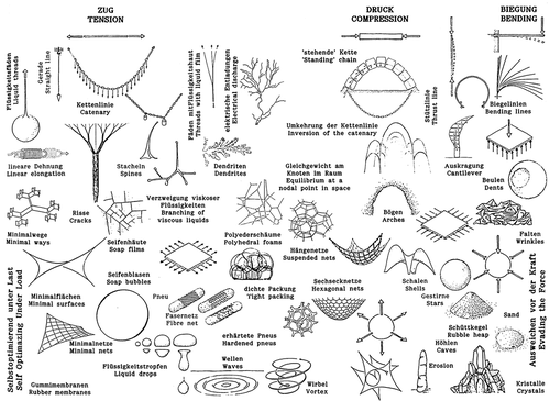
Figure 1. Structures developing from self-forming processes, classified according to the generated forces (Gaß Citation2016).
Although the research on the relationship between bionics and structural mechanics is gradually mature, how to effectively apply the mechanical principles to the conceptual design of building structures is still a topic worthy of exploration. In architectural design, the optimal solution of structural performance is often not the best state of space quality (Xianchuan Citation2019). However, the subjectivity of space aesthetics makes it difficult to optimize the structural mechanism and special aesthetics simultaneously, and the design intentions of designers should be taken into account. Therefore, some scholars tried to balance this contradiction by adding user participation into the iterative elimination of genetic algorithm (Mueller and Ochsendorf Citation2015). There are also methods to reflect user’s subjective preference by clustering algorithm of machine learning (OLE; Saldana Ochoa et al. Citation2020).
The numerical simulation methods can well summarize the structural mechanical features of the research object, but it cannot provide a direct reference for the conceptual design of building structures. In recent years, the development of graphic statics brings up a closer relationship between building structural optimization and architectural morphology. Geometric diagrams have been put forward to express the complex internal force systems, and by comparing the specific force diagrams, the mechanical similarity of the two structural systems can be estimated. With the methodology of graphic statics, almost all kinds of structure concepts and features can be expressed abstractly, thus it enables the principles of bioinspired structures to be converted into understandable principles and then applied in new design contexts.
2. Problem statement and objective
This paper would like to apply graphic statics to extract and reproduce bioinspired principles with an intuitive and controllable workflow. By employing Layout Optimization method and graphic statics, taking human femur as an example, the structural characteristic of bioinspired object is transplanted and recreated. Following this, the interdependent graphs in graphic statics (form diagram and force diagram) are employed to understand the mechanism of structures, and the performance-oriented and space-oriented optimizations are carried out by means of combinatorial and transformational methods. The significant contribution of this research is to propose a visual and understandable process of extracting bionic structure principles. Meanwhile, thanks to graphic statics, the research displays a complete work flow reproducing the features of the bioinspired structures, which can be easily implemented in the conceptual stage of structural design, and fully be merged with the subjective judgment of the architect.
The framework of this paper is as follows. Section 1 introduces the motivation and significance of the research. Section 2 introduces the methodologies, including the analyzing of the stress lines inside the boundary of the bionic object’s profile, which is summarized as the Basic Structural Principle Unit (BSPU) by simplification and combinatorial manipulations. Section 3 introduces the design application with the BSPUs.
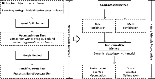
3. Methods
This section introduces the research methodology (). Firstly, this section introduces the process of employing the Layout optimization (LAYOPT) method to obtain the stress lines inside the geometric boundary of the nature form and under the multiple load cases caused by complicated natural environment. After that, the stress lines will be compared with the biological structure of the femur section. Secondly, based on the obtained section stress field lines, the Morph method is employed to simplify the lines, which then will be represented as the basic principle unit of the bionic structure, and its effectiveness is verified by multi-directional loads test. Finally, with the basic principle unit, the manipulation rules and principles based on graphic static are introduced, which merges the performance-oriented optimization with the space-oriented manipulation of bionic structure.
Figure 2. Framework of the methodology.
3.1. Pattern study
Topology optimization is an effective structural optimization method to obtain the optimal force flow under the specific boundary, load cases and support conditions. Among the parameters, the results of topology optimization are often affected by the mesh subdivision degree and the system shrinkage ratio. For qualitative structural research, topological optimization method can well present the trend of internal force flow inside the solid boundary, so as to reveal the underlying mechanical logics of the structure.
Support and load are two decisive factors of topology optimization, and also correspond to the environmental constraints in the context of bioinspired structure. In other words, it can be considered that any natural form comes from the force flow generated by the external forces and constraints in a specific environment. Therefore, for a bionic object, it is necessary to analyze and get its environmental forces and constraints correctly. In this study, the cross section of human leg bone is taken as an example. Fung (Citation1990) and Wolff (Citation1869) have studied the mechanical properties of bone structure long before, and have drawn the stress lines inside the femur structure ( left). At the same time, Culmann’s work also mentioned the similarity between the stress field in cantilever beam and femur bone head in civil engineering.
Figure 3. Femur head principal stress representation (Stoltz et al. Citation2018) and the force condition of the femur in human body.
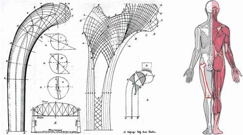
Bone is a kind of dynamic structure, and its stress is usually related to the weight of human body and the stretching activity of muscles. Obviously, the human femur will be subjected to more complex external forces while taking human movements into account. In this study, we only focus on the primary stress state of the femur, which defines that the femur is mainly subjected to the gravity from the body part centered on the spine, and at the same time, it is subject to the tensile force from the muscles ( right). More importantly, because the action force line of the human spine is in the eccentric position of the femur, the femur under the body gravity is more similar to the situation of eccentric column. Therefore, we can employ the principles of bone mentioned above as preconditions to analyze the force flow of the human femur cross-section.
In this study, peregrine, a plug-in based on Rhino Grasshopper platform, is used for topology optimization. Peregrine works mainly based on the topology optimization algorithm library of Limit State Form. Different from traditional topology optimization algorithms (solid isometric material with penalization (SIMP) method and bidirectional evolutionary structural optimization (BESO)), Limit State Form is based on layout and geometry optimization technology (LAYOPT) (Smith et al. Citation2016). The difference is that topology optimization is an algorithm which takes the structural performance (e.g., strain energy) as the optimization objective and finally presents the optimal distribution of materials within a certain range of structural materials for a given load and support. LAYOPT started with a geometric subdivision grid within a predetermined structure range. In the process of iteratively approaching the parameters of structural optimization objectives, the LAYOPT will gradually reduce the components in the grid, and finally come to an after-eliminated form (Dorn, Gomory, and Greenberg Citation1964). The advantage of the latter is that it can output an equilibrium result and present it with strut‐and‐tie model.
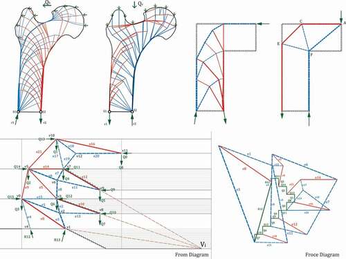
Here, we take the section of normal human femur head area as the experimental object ( ), and its contour as the optimization range
, and apply vertical load
, horizontal load
and double load cases
at corresponding position according to the eccentricity characteristic of the action force to the femur bone. For the configuration of the support, as the middle part of the femur is a hollow tubular structure, the support points are spotted at
and
on two extreme sides of the bottom.
is the filling of the stress lines in femur drawn by Meyer and wolf in the study range
.
,
,
() are the stress line results generated from Peregrine, which corresponds to three load cases:
,
and
. Here in the strut-and-tie models, the blue line represents the compression, and the red line represents the tension. In
, we can see that the pattern of the stress lines at this load case is very similar to Michelle cantilever, and it is consistent with the stress line pattern of
part in
. Since
is equilibrium, the corresponding force diagram
can be drawn according to the form diagram
. According to Cremona (Citation1890), the vector equilibrium of any node in
can be represented with a force polygon in
. Here, we compare the equilibrium state between support
and support
in
. We can see that support
is subjected to multiple compressions in the upper right direction within the range
, is balanced with the support reaction force R1, and corresponds to C1 force polygon in
. Similarly, the support
is subjected to multiple tensions in the upper left direction, is balanced with
, and corresponds to
force polygon in
. Comparing
and
, it can be seen that the vector set balanced with
in
has experienced more angular changes than
. This difference can explain the asymmetry of
and the eccentricity of
. Similarly, we can see that the stress line pattern in
is more consistent with
part in
. Meanwhile, the compressive stress lines mainly concentrate on the cantilever part of the structure and converges to the support
. However,
, which applies horizontal and vertical loads
simultaneously, presents a pattern trend of integrating
and
, and is more in line with the overall characteristics of
. To sum up,
,
,
well verify the characteristics of eccentric force and multi-directional load cases of the femur structure.
Figure 4. The solution of layout optimization inside the .
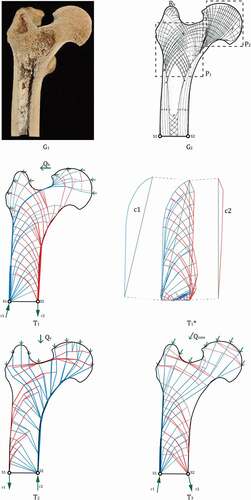
Figure 5. Simplified boundary and LAYOPT result.
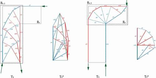
In order to further reveal the distribution logic of stress lines in and
, the femur contour
is simplified and converted to the merged range
of two rectangles (). In this case, the LAYOPT is carried out according to the above load conditions, and the simplified strut-and-tie model
and
are obtained, which are consistent to the
and
mentioned above and can better summarize the stress mechanism of femur structure. In , when the structure is subjected to horizontal loads, the sub range
of
is activated, in which the stress pattern of Michell cantilever is formed, and is corresponds to the force diagram
. When the structure is subjected to vertical loads, the sub range
of
is activated, in which a cantilevered beam is formed, and is corresponding to
. By simplifying the models
and
, we can further judge that the human femur is a kind of statically indeterminate and kinematically determinate structure which can resist lateral and eccentric loads and have the capacity to maintain stability under multi-directional loads. Therefore, we can speculate that the combination of
and
models can well represent the structural features of femur.
3.2. Principle extraction
According to the conclusion in Section 2.1, the basic structural characteristics of femur are eccentric and multi-directional load bearing. The following question is how to express the structural principles contained in and
in a more concise way, with which design manipulation can be put out. Here, graphic statics is employed as a force flow induction and diagramming method to abstract the complex mechanical system and express it with a simple strut-and-tie model. At the same time, Peregrine rationalizes the results of the optimization into an equilibrium strut-and-tie model. This makes the topological optimization model and graphical statics model in the same format.
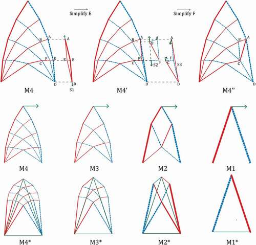
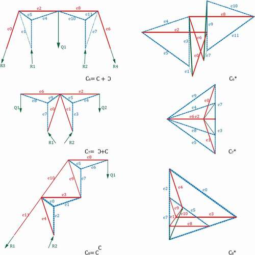
In the simplification of topological optimization model to graphic statics model, we use the Morph method (Meng and Zhao Citation2015), and Meng’s work introduced a variety of methods for transforming structures to equivalent forms by overlapping two equilibrium systems. For example, by using self-stress elements to replace the components in a balanced structure, the subdivision and the reorganization of the internal force relationship are realized. As shown in , by using this method, we can gradually simplify Michelle cantilever (M4) to the simplest double bar cantilever beam model (M1). By using the similar method repeatedly, any strut-and-tie structure obtained by LAYOPT can be simplified step-by-step and approach to the basic structural element. This transformation process will present a regularity, so the process (M4-M1) is reversible (M1-M4), which has become the morphological manipulation rules of specific-basic structural principle units (BSPU).
Figure 6. The Michell Cantilever simplifying process with the Morph method from Meng.
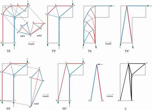
Now, we can use Morph method to further simplify and
. As shown in , in
, the equilibrium substructure
is superimposed on
. At this time, the tension bar
is offset with the compression bar
, and the compression bar
,
are respectively offset with the tension bar
and
, and the compression bar
,
are superimposed with the compression bar
and
, and simplified to
. Similarly,
can be obtained by superposition of
and
. By repeating this process, we can obtain simplified models
and
from model
and
. Based
and
, the structural mechanism model of femur structure can be correctly established by combining these two models. The process of combining
and
is quite obvious.
can be obtained by superposition of
with
. In this case, by combining the morphology of
and
, the set model
can be obtained.
Figure 7. Combining two optimized model to make the basic structural principle unit (BSPU) .
The model can be regarded as the basic structure principle unit (BSPU) of human femur. It is expected that model
can correctly represent the structural features of femoral structures: eccentric and multi-directional load-bearing. In order to verify this, a multi-directional load-bearing capacity experiment is carried out (). In the test, four models were set up:
, a simple cantilever consists of two elements directly connecting the load action point and the support;
, a composite structure composed of two simple cantilever beams without considering the boundary constraint
;
, the model with boundary constraints and consistent topological relationship with
model;
, obtained from the force subdivision of
. The loads
with different angles and equal length are applied, respectively, to these four models. Here, we take the peak value of the internal forces of all the elements in the structure as the value evaluating the limit state of the model under the load. Then the peak values can be expressed as following:
Figure 8. Stability test under multi-directional loads.
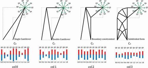
Where represents the set of all the internal force values
, where the count of
is
, while the structure
is under the load case of
.
and
represent the maximum and minimum tension forces under
.
and
represent the maximum and minimum compression forces under
.
The bar chart respectively shows the peak values of internal forces of
under the loads
. It can be seen from the histogram that the peak values of
is the highest among all models under the loads
, and has a huge fluctuation with the change of direction, which indicates that the material’s limit state is easier to be reached in structure
under the multi-directional loads. The peak value of
is slightly lower than that of
, but there are still obvious fluctuations, which indicates a certain improvement. The peak value of
is equivalent to
, but the peak value under each load is generally greater than that of
and
, but the fluctuation is significantly reduced. It shows that
is lower than
in general structure performance, but the material performance is more stable. The peak value and fluctuation of
are significantly lower than those of
, which indicates that the subdivision model
based on
has better multi-directional load bearing capacity. According to this test, it can be verified that
and its subdivided model have the same structural characteristics as the femur.
3.3. Principle reproduction
With the approaches introduced above, the BSPU of human femur is achieved. This section shows how to manipulate and combine basic unit
, so as to apply it to specific design context with similar structural requirements. For the manipulation of structural units, it should be ensured that all the manipulation of structural units will not change the global equilibrium, so certain rules need to be followed. In this study, the manipulation of the BSPU under equilibrium mainly includes two parts: combinatorial operation and transformational operation.
3.3.1. Combinatorial operation
The combinatorial operation can be divided into two cases, one is the self-combination of one BSPU, the other is the mixed superposition of different BSPUs. Self-combination is the repetition and superposition of one kind of structural principle unit. As shown in , we can achieve new conceptual model , respectively, via mirror and overlapping the BSPU
. By drawing the force diagrams
of them, it can be observed that the equilibrium connections between the elements inside the BSPU are retained in the new model and are repeatedly nested. This means the self-combination of one BSPU can generate new structural prototypes with similar mechanical characteristics with the origin BSPU.
Figure 9. The new structural prototype model generated from self-combination of one BSPU.
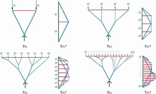
The other is the mixing of different BSPUs, which could also bring multiple structural features into one design model, meanwhile, the load case of the structure might be changed, but the equilibrium of the system will not be changed. Here we introduce another structural bionic principle unit: . This paper does not introduce the detailed acquisition process of
, and directly employ the principles of Tree for manipulation. As shown in , the geometric and operational rules of Tress are
Branching and
Subdivision. The combination of these two operations not only creates a rich tree like branch morphology
, but also effectively decomposes the concentrated load into subdivided loads, and into more smaller cross-section elements, like in
.
Figure 10. structure principle derivation by graphic static.
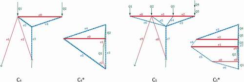
The unit can be well combined with Femur unit. The load of the BSPU of femur structure is set as a concentrated and eccentric load. We can decompose the load by employing the two operations of the
, so that the concentrated load can be changed into uniform load plus eccentric load. As shown in ,
is the BSPU of femur subjected to concentrated loads
and
. By using subdivision operation,
and
in
can be decomposed into equivalent five loads:
,
,
,
and
in
. The
can be obtained by combining the principle of
and the
. The model retains the characteristics of force decomposition of tree structure, eccentric force and multi-directional load-bearing of femur structure. By comparing
and
, it can be seen that the combined force diagram
does not change the topology itself, but is subdivided locally.
Figure 11. The new structural prototype model generated from combining two different BSPUs.
3.3.2. Transformational operation
When we achieved an initial structure by means of combinatorial operation, it can be considered that the structure represents the structural bionic mechanisms of one or more natural forms. However, the specific design context is complex and diverse, just as the same species in nature will show different characteristics in different geographical regions and climatic environments. This population diversity feature is studied in Thompson’s work on transformation (Thompson Citation1942), in which the deformation stretching of images is mainly used to explain the diversity and similarity of biological characteristics. Here, similar to biodiversity, the initial structure also needs to be manipulated to adapt to the complexity of the environment. But this transformation is not random operation, it needs to keep equilibrium in the process. Therefore, here the dual transformation approach of graphic statics is studied and introduced, in which the entire process of transformation maintains the specific geometric connection between the form diagram and the force diagram: 1. The corresponding edges keep parallel; 2. The form diagram and the force diagram are always reciprocal. As a result, the structure represented by the form diagram is always equilibrium. Meanwhile, according to the basic principle proposed by Culmann 1864 and Maxwell 1864, some scholars have studied the transformation methods for the form and force diagrams (D’Acunto et al. Citation2017). Here, this paper mainly employs the dynamic relaxation algorithm to do the transformation operation. This algorithm is mainly based on the physical simulation plug-in kangaroo 2 in grasshopper. The reciprocal state between the form diagram and the force diagram is set as the geometric constraints, and then two graphs are put into the dynamic relaxation solver of kangaroo 2 at the same time. During the operation of the solver, the slow movement of any node will lead to the dissatisfaction of the geometric constraints. The dynamic relaxation method makes each node try to move, and tends to a new geometric equilibrium relationship, which makes the form and force diagram reciprocal in a new state. By this method, the structure form can be transformed in the state of equilibrium.
4. Design applications and integrated optimization
This section explains how the BSPU of femur structure is applied in the structural conceptual design in a specific architectural design context. The basic model of femur structure in Section 2.3 can be regarded as the most simplified initial model to describe the features of eccentric and multi-directional load-bearing mechanism of femur. Now we try to apply model
to the structural design of a stadium.
4.1. Context for designing the proposed stadium
Structural span requirements: The precondition of the span can be seen in . In this case, a stadium that can accommodate a standard football field (68 * 105 m) is to be designed. At the same time, the stadium needs a stand and service space with a thickness of 40 m, of which the service space is required to be at least 18 m (yellow lines). The span of the stand space is about 22 m, and it needs to have 3 floors (each floor is 15 m high). On the top of the three-story stands is the roof of the stadium, and the roof should be formed like a cantilever to provide a sunlight shield to the audience.
Figure 12. The diagram of the preconditions of the stadium (left); The BSPU applied to the design (right).
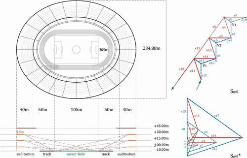
Auditorium vision requirements: In this case, the auditorium is considered to be seats installed on the slope of a standard public staircase. Therefore, in the conceptual design stage, the slope of the auditorium can be regarded the same as the slope of the auditorium floor, so here we define the angle of inclination of the upper floor is α < π/6. At the same time, an illegal value of α will inevitably lead to the audience’s field of view cannot reach the edge of the soccer field. Thus, in this example, we also configure that the line of sight of the last row of the auditorium must reach the edge of the soccer field, and this also acts as the auxiliary lines to decide the tolerated vision range (dark red dashed line ).
Basic Structural Principal Unit composition: As shown in right, based on this basic functional requirement, the BSPU is repeated in the vertical direction, and combined as
. And there being that the force at the support in
is always the load of next layer
.Therefore,
is a cantilever structure with three layers of repeating sub cantilever structure.
is the corresponding force diagram. It can be seen that
,
,
are similar triangles with scaling relationship, showing the characteristics of downward transmission of cantilever force flow.
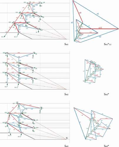
Designing structural system with main cross section: According to the functional requirements of the stadium, we also need to consider the structure of the stand, so we add a cantilever beam to the three units in to form
. As shown in the , model
is produced with local modifications of
and thus forms a better frame representation of the initial structural cross section of the proposed stadium. In addition, for a conceptual design stage stadium, here we dominantly focus on the main cross section of the entire structural frame, because it is not hard to verify that the form of the cross section determines the overall performance of the system.
Figure 13. Stadium section form finding by transformation method in graphic static.
The aim of structural form finding: The dominant purpose of the graphic static-based form finding is to show and verify the interactivity and rationality feature of the method. More importantly in this paper, the process of transplanting and reusing of BSPU to one specific design context demonstrate the sense of the bioinspired design method. Therefore, the following content will focus on how to optimize the structural from the perspective of the structural performance and architectural function. The optimization process will show the great potential of this method in the conceptual design stage for both architecture and structure.
4.2. Performance-oriented structural optimization
According to obtained with the composition of
,
is the in-site configuration of
, which fit the size of the stadium preconditions. Based on the model
and the corresponding force diagram
, first we try to use the transformation method in Section 2.3 to optimize the structural performance of
. In
, it can be seen that nodes
,
and
correspond to three similar triangles (force polygons)
,
,
in
respectively, and these three triangles occupy a relatively large space in the force diagram (which means that the internal force values are large). Therefore, if we can minimize the edges
,
,
in
, then the structure will surely be optimized because it takes smaller inner forces to keep equilibrium. Based on Kangaroo2’s practical dynamic system model, we can move
,
,
nodes in
, and observe the geometric changes of corresponding triangles in
. Through the manipulation, we find that under the premise of keeping other points unchanged, we move
,
,
to the right and down at the same time, which makes
,
,
in
are significantly reduced, and other forces in the force diagram are also reduced by this geometric change. In addition, we can also try to minimize the load path inside the structure by changing the structure form to a very orthogonal state, like
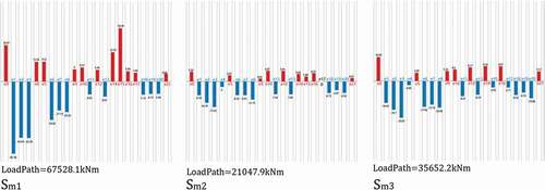
. At this state, we compare the internal force histogram () corresponding to
and
, and we can see that the geometric modification makes the tension and compression values in the elements of
decrease significantly, meanwhile, the load path value and internal force variance value of the structure are both significantly reduced.
Figure 14. The statistics of the three configurations.
From an intuitive point of view, it can be seen that the boundary area of is obviously smaller than
, and the external forces in these two force diagrams are still unchanged. This means for the same global equilibrium state, more efficient structure configuration means the shorter path between the loads and supports. In addition, the optimization based on transformation is not limited to empirical or consciously manual derivation, but also can resort to optimization algorithms such as genetic algorithm and gradient descent to analyze the trend of transformation. Nevertheless, even though the
is proved to a very efficient structural configuration, the form of
is quite incompatible with the requirements of architectural function and space. It can be seen in that the form of
totally lost the characteristic of cantilever structures and forms a monotonous space experience. So, the structural-oriented optimization result
requires further modifications to take space and function issues into account.
4.3. Function-oriented structural optimization
Once we find the structural optimized configuration , further explorations aiming to fit the architectural demands are put forward to find solutions that are good in both performance and perceiving. The significant advantage of the geometric-based method is that all the modifications the designers drawn on the form diagram have a corresponding change on the force diagram. This means one can be aware of the advantages and disadvantages of each manipulation he did on the designing form and this information can well guide him to make decisions.
Here, the space span requirements in the design preconditions (Section 3.1) can be regarded as the basic rules for optimizing the space. It has to been insured that every last line of the auditorium on the stand can have an unobstructed view toward the closest edge of the soccer field in . Meanwhile the angle of each stand slope should be minor than π/6. With these rules in mind, it is also proposed that the cross section of the stadium shows a trend of cantilever to maintain the esthetic perception of
, which means the visitors can see an organic building façade instead of the simple overlapping of one element (like in
).
Figure 15. Stadium space based on three structural solutions.
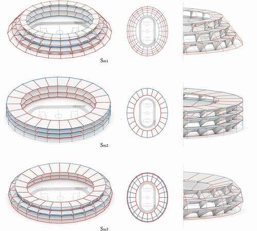
The model embodies one of the results of structural optimization started from
and considering the architectural space and function. The process of optimization is mainly composed of two parts. The first part is to observe the change trend of form diagram by manipulating the force diagram, it is similar to the process in Section 3.2, so as to judge what kind of form modification can improve the structural performance. Based on this understanding, the second step is to manipulate the form diagram, and simultaneously try to meet the requirements of architecture, while minimizing the volume of the force diagram. In
, the incline angles of the stands have met the sight requirements, and it does not change the topology of
. By comparing the internal force histogram of
and
(), it can be seen that the internal forces of the structure are optimized and the variance between the values of internal forces is reduced. By comparing the internal force histogram of
and
, we can see the
sacrificed little mount of performance to fit the space requirements. Thus, it is nearly impossible to find both perfect solution on performance and esthetic. The optimization workflow to find
shows an impact consistence with the real case workflows, which also contain lots of negotiations between the form and force, the esthetic and functionalism.
5. Discussion
For the case study above, discussion and analysis from multiple perspectives can be carried out:
5.1. Form and force manipulated optimization with consciousness
In the general structural optimization process, it is difficult to rationalize how to improve the performance of the structure by changing the form of the structure. Some numerical-based optimization algorithms can provide an optimized morphological solution in a “black box” manner, which will be extremely difficult for architects to comprehensive the underlying logic of the optimization. In the above-mentioned performance-oriented optimization process, based on the interdependency between the form diagram and the force diagram, the values of forces required to equilibrate each node in the structure (the corresponding force polygons in the force diagram) is clear at a glance. Therefore, the architect can quickly understand the force flow logic of the structural system through the force diagram, and then quickly obtain the corresponding strategy for optimizing the structure.
5.2. The explicit logic of bio-inspired principle transplantation
In this case, BSPU was introduced as a structural prototype, and an initial structural framework was formed through the composition of BSPU in the design context. Inspired by the structural features of the human femur, the structural frame itself has good structural features. For example, as a rigid structure, it can carry loads in multiple directions and is an efficient cantilever structure. By transplanting into the design scene, the section of the stadium case inherited the structural principles inspired by biology, forming a kind of bionic process based on principle rather than image imitation. In , you can see the abstract expression of the structure of the human femur: an eccentrically stressed and overhanging curved structure frame. This method, to a certain extent, gets rid of the necessary process of transplanting its performance by imitating the external shape of the creatures in the traditional bionic methods.
5.3. The game between space and performance in the conceptual design stage
Graphic statics is an effective design tool in the conceptual design stage of structures, and its purpose is not to carry out “generative” design in accordance with certain established rules or parameters. By comparing the relationship between structural form and performance in the three states of ,
and
in the above cases. It can be seen that the optimal state of structural performance is not the optimal state of the building space. This contradiction runs through the entire design process. As shown in , in the
state, it can be seen that its spatial expression is dramatic, because the structure forms an exaggerated cantilever, and the structure holds large internal forces to achieve equilibrium (LoadPath = 67528.1 kNm) (). At the same time, the functional requirements of the architectural space cannot be met under this condition.
embodies another extreme. Through rational structural optimization, the path of force flow from loads to the supports in
becomes direct and efficient (LoadPath = 21047.9 kNm) (), which also significantly reduces the spatial expressiveness of the structure.
is the neutralized result of these two extremes. In this state, the structural efficiency is only slightly lower than
(LoadPath = 35656.2 kNm) (). Nevertheless, the space function and structure of the gymnasium are optimized. The above analysis further shows that the transformation method used in this article is a method that serves the synchronized design of structure and building. To a certain extent, it allows architects to obtain the ability to design architectural space and structural form simultaneously.
5.4. From conceptual design to detailed design
The design process based on the graphic static transformation method introduced in this paper is mainly oriented to the morphological derivation at the conceptual stage. Obviously, judging from the preliminary model, it is far from the final implementation stage of the structure. However, based on the conceptual model, the equilibrated modification and optimization of the structure can be carried out through further graphic statics methods. For example, the
and
members in
are two structural members that significantly disturbing the integrity of the space in architecture, but this problem can be solved by replacing these two members with the Morph method introduced in Section 2.2. Therefore, the further detailed design strategy of the structural conceptual model is the content that has not been discussed in this article.
6. Conclusion
This paper introduces a complete process for obtaining the BSPU from nature references and reproducing the related principles in the new design context. In the stage of observation and extraction of natural forms, the LAYOPT method is employed to analyze and extract the mechanical mechanism of human femur section. On this basis, the Morph method (the equilibrium component replacement method) in graphic statics is used to simplify the strut-and-tie model of the femur section, and the basic model that contains the mechanical mechanism is deduced, and consequently be summarized as the BSPU of the femoral structure. Based on the BSPU, through the combinatorial and transformation principle in the graphic statics, it is introduced that how these BSPU are implemented to specific architectural design scenarios, and how to perform structural morphologic manipulation that take into account the architectural space and structural performance.
The workflow and geometric optimization method of the bioinspired structure proposed in this paper have the following significance:
1. In general bioinspired structure research, the principle of bionic objects is very difficult to define and quantify, and it is very dependent on the basic work of mature biological research. This paper proposes to use the LAYOPT method to study the force flow of the cross-sectional structure. With the favor from LAYOPT, the ideal force flow lines generated under certain boundary condition can be obtained, which is consisted with tension and compression in a equilibrium state, and clearly presents the load bearing mechanism of the nature reference. By employing the Morph method of the graphic statics, the structural principle of the bionic object can be scientifically and intuitively discussed through the form and force diagrams.
2. At the level of off-site principal reproduction of the bioinspired structures. The traditional method of bionics relies heavily on the similarity of the image level to maintain the consistency of performance from the bionic reference to the reproduced object. This paper proposes to summarize the mechanical mechanism of the bionic reference as a BSPU, and realize the bionic at the performance level through various deductive manipulations to the BSPU. And the manipulating process of the BSPU is very consistent with the design process of architectural design. The fascinating thing is that it can generate synchronous feedback for both form and force throughout the conceptual design stage.
3. In the phase of structural optimization. As a comparison to the traditional numerical optimization methods which are conducted with purely mathematical parameters and almost leads to the solutions without architectural consideration, the introduced method with graphic static synchronously optimizing the form and force by manipulating two interdependent graphs. Meanwhile, unlike the purely numerical value results from the “black boxes”, the structural performance expressed by force diagrams is not only a scalar in a single dimension, but a whole with geometrically variable properties. The change of any internal force scalar may cause other internal force scalar changes. Therefore, the structural optimization method based on the geometric expression in this paper in some degree reveals the underlying logic of the interdependency between the structural performance and architectural space and provide designers a tool to find forms in-between the equilibrium range.
At the same time, due to space limitations, there are further issues worthy of study:
1. The method of extracting the principle of bionic objects involved in this article is temporarily only applicable to cross-sectional structures, not works as a general approach to deal with all-natural structural references. For example, the “tree” structure mentioned in the paper requires a specific approach to find the basic principles and mechanisms.
2. This article only discusses the methods of structural bionics and re-production from a two-dimensional manipulation perspective. Long-term research will try to develop the bionic principle unit into a three-dimensional structure.
3. The combination of numerical optimization and geometric optimization has not yet been discussed. This open question may facilitate the new use of the numerical methods to a more architectural way and the improvement of the accuracy of the evaluating values for the optimized structures.
4. As mentioned above, the current introduced method is mainly for the conceptual design stage, which means the detailing design stage also draws an important role to the proposed building. In this way, how to keep the structural principle consistency between these two stages is a question deserve answering.
Disclosure statement
No potential conflict of interest was reported by the author(s).
Additional information
Funding
Notes on contributors
Yuchi Shen
Yuchi Shen, Ph.D candidate, School of Architecure, Southeast University, Nanjing, China. Main research field in architecture and strucutre intergrated design by Graphic Static.
Yan Liu
Yan Liu, Ph.D candidate, School of Architecure, Southeast University, Nanjing, China. Main research field in design by architectural linguistics theory.
References
- Ball, P. 2001. The Self-Made Tapestry: Pattern Formation in Nature. USA: Oxford University Press.
- Ball, P. 2009. Natures Patterns. A Tapestry in Three Parts. USA: Oxford University Press.
- Chilton, J. C. ( Prof.). 2011. “Eminent Structural Engineer: Prof. Dr Heinz Isler (1926–2009).” Structural Engineering International 21 (1): 124–126. doi:10.2749/101686611X12910257102875.
- Cremona, L. 1890. Graphical Statics: Two Treatises on the Graphical Calculus and Reciprocal Figures in Graphical Statics. Oxford: Clarendon Press.
- D’Acunto, P., J.-P. Jasienski, P. O. Ohlbrock, and C. Fivet. 2017. “Vector-Based 3D Graphic Statics: Transformations of Force Diagrams.”
- Dorn, W. S., R. E. Gomory, and H. Greenberg. 1964. “Automatic Design of Optimal Structures.”
- Fung, Y. C. 1990. Biomechanics: Motion, Flow, Stress, and Growth. Edwards Brothers. Inc., Ann Arbor.
- Gaß, S. 2016. “Physical Analog Models in Architectural Design.” International Journal of Space Structures 31 (1): 16–24. doi:10.1177/0266351116642061.
- Gruber, P., D. Bruckner, C. Hellmich, H.B. Schmiedmayer, H. Stachelberger, and I.C. Gebeshuber. 2011. Biomimetics Materials, Structures and Processes. London New York: Springer Heidelberg Dordrecht. doi:10.1007/978-3-642-11934-7.
- Huerta, S. 2006. “Structural Design in the Work of Gaudí.” Architectural Science Review 49 (4): 324–339. doi:10.3763/asre.2006.4943.
- Maghsoudi-Ganjeh, M., L. Lin, X. Wang, and X. Zeng. 2019. “Bioinspired Design of Hybrid Composite Materials.” International Journal of Smart and Nano Materials 10 (1): 90–105. doi:10.1080/19475411.2018.1541145.
- Meng, X., and C. Zhao. 2015.“Generating Graphic Statics: Introducing a Morphing Method of Form Finding.” Proceedings of the International Association for Shell and Spatial Structures (IASS) Symposium,Amsterdam, IASS2015–521653.
- Mueller, C. T., and J. A. Ochsendorf. 2015. “Combining Structural Performance and Designer Preferences in Evolutionary Design Space Exploration.” Automation in Construction 52: 70–82. doi:10.1016/j.autcon.2015.02.011.
- Saldana Ochoa, K., P. O. Ohlbrock, A. P. D, and V. Moosavi. 2020. “Beyond Typologies, beyond Optimization: Exploring Novel Structural Forms at the Interface of Human and Machine Intelligence.” International Journal of Architectural Computing: 147807712094306. doi:10.1177/1478077120943062.
- Siegfried, G. 1990. “Experiments – Physical Analog Models in Architectural Design.” In Information of the Institute for Lightweight Structures: IL 25 Experiments, edited by F. Otto, 288. Stuttgart. doi:10.1177/0266351116642061.
- Smith, C. J., M. Gilbert, I. Todd, and F. Derguti. 2016. “Application of Layout Optimization to the Design of Additively Manufactured Metallic Components.” Structural and Multidisciplinary Optimization 54 (5): 1297. doi:10.1007/s00158-016-1426-1.
- Stoltz, J.-F., J. Magdalou, D. George, Y. Chen, Y. Li, N. De Isla, X. He, and Y. Remond. 2018. “Influence of Mechanical Forces on Bone: Introduction to Mechanobiology and Mechanical Adaptation Concept.” Journal of Cellular Immunotherapy 4 (1): 10–12. doi:10.1016/j.jocit.2018.09.003.
- Thompson, D. W. 1942. On Growth and Form. Cambridge: Cambridge University Press.
- Wolff, J. 1869. “Überdiebedeutung der architektur der spongiösenSubstanz.” Zentralblattfür die medizinische Wissenschaft 6: 223–234.
- Xianchuan, M. 2019. “An Architectural Design Method Based on Bending Moment Diagrams.” Architectural Journal (6): 84–89. doi:10.3969/j.0529-1399.2019.06.011.
- Xie, Y. M., and G. P. Steven. 1993. “A Simple Evolutionary Procedure for Structural Optimization.” Computers & Structures 49 (5): 885–896. doi:10.1016/0045-7949(93)90035-C
- Xie, Y. M., and G. P. Steven, 1997. “Basic Evolutionary Structural Optimization.” Evolutionary Structural Optimization. Springer, London. doi:10.1007/978-1-4471-0985-3_2
- Yang, X. Y., Y. M. Xie, G. P. Steven, and O. M. Querin. 1999. “Bidirectional Evolutionary Method for Stiffness Optimization.” AIAA Journal 37 (11): 1483. doi:10.2514/2.626.
- Zhao, Z.-L., S. Zhou, X.-Q. Feng, and Y. M. Xie. 2018. “On the Internal Architecture of Emergent Plants.” Journal of the Mechanics and Physics of Solids 119: 224–239. 0022–5096. doi:10.1016/j.jmps.2018.06.014.