
 ?Mathematical formulae have been encoded as MathML and are displayed in this HTML version using MathJax in order to improve their display. Uncheck the box to turn MathJax off. This feature requires Javascript. Click on a formula to zoom.
ABSTRACT
The nonlinear dynamic analysis is the most sophisticated evaluation method for vertically irregular structures under the effect of the earthquake because the higher mode effects are significant. In particular, vertically irregular structure has a complex geometry, so errors can occur when inputting members as coordinates or when defining the properties of members. Therefore, a simplified modeling method is proposed in this paper. The proposed method was developed by converting vertically irregular structures to geometrically regular structures using a story stiffness equation. The results of modal analyses and nonlinear dynamic analyses obtained by both simplified and typical exact modeling methods were compared. As a result, the difference of fundamental period was about 11%, and the higher mode effects which were evaluated by ASCE 41 criterion governed in both models. In addition, the differences of story shear and story drift were about 15% and 24%, respectively. Therefore, the proposed simplified modeling method can be applied to initial structural design stages to save the project time by predicting approximate nonlinear dynamic results such as story shear, and story drift of vertically irregular structures.
1. Introduction
The buildings had numerous irregularities along with the height or the planar directions. For the irregular buildings under the effect of the earthquake, the first mode participation is decreased and participation on higher modes is increased (Sarkar, Prasad, and Menon Citation2010). There will be a large error during pushover analysis if the higher mode effect is significant because the basic assumption of pushover analysis is that the structure vibrates predominantly in a single mode (Esfahanian and Aghakouchak Citation2019; Azizi-Bondarabadi, Mendes, and Lourenço Citation2019). Therefore, the nonlinear dynamic analysis should be conducted to accurately evaluate the seismic performance of irregular structures. Although the nonlinear dynamic analysis is the most sophisticated evaluation method for the seismic performance of the building, disadvantages exist such as being time consuming and complicated to analyze.
According to the literature review, recent researches about nonlinear dynamic analysis focused on two main topics as follows:
Method for conducting pushover analysis with accuracy comparable to nonlinear dynamic analysis
Method for validation dynamic behavior and seismic assessment of irregular structures
The studies which focused on the pushover analysis method should consider different loading vectors that can reflect the time-history analysis and attempt to account for higher mode effects. They have proposed methods for modal pushover analysis, N2 method and converting ground motion to lateral load pattern to enhance accuracy and maintain simplicity in pushover analysis (Esfahanian and Aghakouchak Citation2019; Azizi-Bondarabadi, Mendes, and Lourenço Citation2019; Chopra and Goel Citation2002; Shakeri, Shayanfar, and Kabeyasawa Citation2010; Abbasnia, Davoudi, and Maddah Citation2013; Kreslin and Fajfar Citation2011; Poursha, Khoshnoudian, and Moghadam Citation2009, Citation2014; Bhandari et al. Citation2018). Chopra and Goel (Citation2002) proposed a modal pushover analysis to obtain the target roof level displacement through a nonlinear response history analysis of nonlinear equivalent single-degree-of-freedom systems for each mode to take into account the effects of higher modes. However, this approach has the disadvantage of performing a nonlinear response history analysis for each mode. Another study on the enhanced pushover analysis method was based on pushover procedures in which the load vectors are updated to consider the modal characteristics of system during the inelastic phase (Shakeri, Shayanfar, and Kabeyasawa Citation2010; Abbasnia, Davoudi, and Maddah Citation2013). Kreslin and Fajfar (Citation2011) extended the N2 method in order to take into account higher mode effects in elevation based on the assumption that the structure remains in the elastic range when vibrating in higher modes. In this extended method, the seismic demands in terms of displacements and story drifts were obtained by enveloping the results of basic pushover analysis and standard elastic modal analysis. Another method for the consecutive modal pushover analysis was proposed, which determined the final structural response using a single- or multi-stage pushover analysis to take the effects of higher modes into account (Poursha, Khoshnoudian, and Moghadam Citation2009, Citation2014). In addition, the studies conducted to simplify the procedure of replacing nonlinear dynamic analysis with nonlinear static analysis through dynamic load pattern considering the characteristics of ground motion using as a lateral load pattern (Esfahanian and Aghakouchak Citation2019; Bhandari et al. Citation2018). The main objective of these studies was maintaining simplicity of pushover analysis, but they were still complex in modeling stage; In earthquake engineering practices, the nonlinear analysis including pushover analysis requires inputting the locations of all members as coordinates and setting the nonlinear properties for all members when using commercial software at modeling stage (CSI Citation2011; Kumar and Sahoo Citation2021).
Recently, the studies focused on the validation dynamic behavior and procedure for the seismic assessment of irregular buildings to improve the nonlinear static procedure (Cancellara and De Angelis Citation2017; Oyguc, Toros, and Abdelnaby Citation2018; Cancellara and De Angelis Citation2019; Marino, Cattari, and Lagomarsino Citation2019; Aşıkoğlu et al. Citation2020). In particular, vertically irregular structures have now become of considerable interest in seismic research (Mazza, Mazza, and Vulcano Citation2015). Vertical irregularities occur due to various variables such as the presence of walls and wall heights, and vertically irregular structures show dynamic behavior characteristics different from those of regular structures (Moehle Citation1984; Shojaei and Behnam Citation2017). However, almost all the codes specify irregularity of structure without detailed discussions, and there were no consensus-based guidelines for seismic design of vertically irregular structures (Das, Dutta, and Datta Citation2021). In particular, the structural design for irregular structures usually required complex modeling procedures, it is necessary to develop the simplified modeling method to save time on seismic assessment.
This paper proposed the modeling method which can simplify the process of defining the coordinates and nonlinear properties of each member. This study focused on vertically irregular structures. The proposed modeling method is for estimating the nonlinear dynamic results of irregular structures such as story shear and story drift approximately. This simplified modeling method should be helpful for practical engineers when estimating approximate nonlinear dynamic results for vertically irregular structures without modeling errors and can save the project time. It is more economically by reducing complex modeling step in the initial design stage before schematic design. In order to simplify the modeling process, converting vertically irregular structures to geometrically regular ones was utilized by changing story stiffness. The modal and nonlinear dynamic analyses for both detailed and simplified models were performed and compared to examine the validity of the proposed modeling method.
2. Proposed modeling method for vertically irregular structures
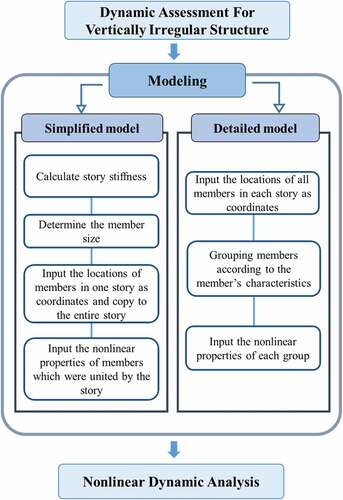
In this study, the simplified modeling method is proposed, which can estimate results such as story shear and story drift for dynamic assessment of vertically irregular structures. The proposed modeling method as follow:
Calculate story stiffness of target structure
Converting target structure to geometrically regular structure
Input the locations of members in one story and copy to the entire story
Input the nonlinear properties of member which were united by the story
This method using story stiffness for converting vertically irregular structure to geometrically regular structure as shown in . This simplified method can be used at initial structural design stages to estimate nonlinear dynamic behavior briefly. The analysis process using detailed model was compared with the process using the simplified modeling of this study as shown in . To evaluate nonlinear dynamic behavior accurately, the locations of all members should be put as the coordinates and set the nonlinear properties for each member, and then perform a nonlinear dynamic analysis. According to manual of PERFORM 3D commercial software, which can conduct nonlinear analysis, the area and coordinate location for each fiber in the cross-section should be specified and each line must contain the H1, H2 and V coordinates of the node, separated by commas (CSI Citation2011). In the case of vertically irregular structures, this method takes a lot of time because the shape is complex, and there is possibility of inputting coordinates and properties of members incorrectly. In this study, the story stiffness of vertically irregular structure was calculated. The story stiffness was obtained by summing the stiffnesses of all columns at a story. The stiffness of column was calculated by EquationEquations (1)(1)
(1) –(Equation3
(3)
(3) ) which were presented by Schultz (Citation1992). After that, a geometrically regular structure with the similar story stiffness was designed; The member sizes such as beams, and columns were adjusted. Since the story stiffness is adjusted by the size of the member, it is practically difficult to design it to have the perfectly same story stiffness. Therefore, in this study, an error of story stiffness between the detailed model and the simplified model is allowed up to 5%.
Where is stiffness for an interior column,
is for an exterior column,
and
is the flexural stiffnesses of the girders framing into the joint above and the joint below the column respectively. The story height is considered as a factor,
to simulate the effect to adjacent stories with unequal heights on intermediate story stiffness.
Figure 1. Schematic of simplified method.
Figure 2. The comparison of analysis processes.
The modal analysis and nonlinear dynamic analysis of simplified models and detailed models were performed to analyze the validity of proposed modeling method. For detailed models, stepped structures (SS) and tower structures (ST) were considered because they are typical types of vertically irregular buildings (Sarkar, Prasad, and Menon Citation2010; Bhosale, Davis, and Sarkar Citation2017). This detailed models are presented in . In , SS-1 and ST-1 were numerical models of Group 1, the rest were Group 2. Groups 1 and 2 are divided according to the floor in which the vertical irregularity is considered. The vertical irregularity was modelled on the 4th floor for Group 1, and the 2nd floor for Group 2. The story stiffnesses of detailed models were calculated by EquationEquations (1)(1)
(1) to (Equation3
(3)
(3) ) which were presented by Schultz (Citation1992). is shown story stiffnesses of detailed models which were calculated by Schultz’s equation. The vertically irregular models (SS and ST) were converted to simplified model (SM) with geometrical regularity as shown in . In , SM-1 and SM-2 were simplified models for detailed models in Group 1 and Group 2, respectively. The member sizes and reinforcement of simplified models were determined to having equal story stiffnesses with detailed models. All of the numerical models assumed an eight-story office building, and they were designed as RC moment frame structures based on ACI 318 (ACI Citation2019). The span length and floor height of the numerical model were 6000 mm and 3000 mm, respectively, and all of the floors were identical. In the case of SM-1 and SM-2, the dimensions of beams and columns in the parts where story stiffness ratio was changed; the beam was designed with a width of 150 mm and depth of 400 mm, and the columns were designed with a width and depth of 400 mm. The numerical models were designed with a dead load of
and live load of 4
, referring to ASCE 7 (Structural Engineering Institute Citation2016). The compressive strength of concrete and the yield strength of the reinforcement were 24 MPa and 500 MPa, respectively. The section information of the numerical model are summarized in .
Figure 3. Detailed models (mm). (a) Front elevation of SS-1. (b) Front elevation of ST-1. (c) Front elevation of SS-2. (d) Front elevation of ST-2. (e) Side elevation of every specimen. (f) Reinforcement details of beam. (g) Reinforcement details of column.
Figure 4. Simplified models (mm). (a) Front elevation of SM-1. (b) Front elevation of SM-2.
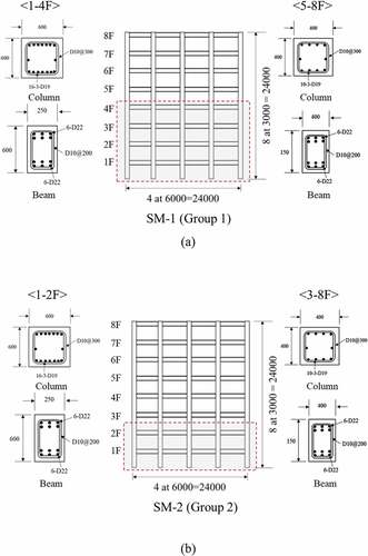
Table 1. Story stiffnesses of detailed models.
Table 2. Section information.
The nonlinear dynamic analysis was performed using the commercial structural analysis software PERFORM-3D. In PERFORM-3D, the nonlinear components are based on the force-deformation relationship (CSI Citation2011), as shown in . To establish the numerical models, the member strength was calculated and modeling parameters and acceptance criteria for nonlinear procedures of reinforced concrete (RC) beam or column are determined as specified in FEMA 356. This study used the FEMA Beam, Concrete Type, which is provided in PERFORM-3D, to reflect the nonlinear characteristics of the beam. This component was used to create a bending moment-rotational plastic hinge, as shown in . The FEMA Column, Concrete Type was used for the nonlinear characteristics of the column member, which contained inelastic axial hinge and moment hinge of column. In general, the column condition was determined by the failure mode of the column, which was classified by the details of the type of hook used in the hoop. The cyclic energy dissipation factors reflecting the energy dissipation capacity of the member. Perform-3D allows the user to select the relationship between the maximum strain in a given hysteresis loop and an associated energy factor. Energy factors represent the ratio of the area of the degraded hysteresis loop over the area of the un-degraded loop and are typically calibrated using test data. This paper used energy dissipation which referred to Khaloo et al. (Citation2016) as shown in .
Figure 5. Force-deformation relation (CSI Citation2011).
Figure 6. FEMA beam, concrete type.
Table 3. Cyclic energy dissipation factors.
According to KDS 411700: 2019 (KSCS Citation2019) which is seismic design code of South Korea, three (or more) or seven (or more) ground motions were required since nonlinear dynamic analysis varied greatly depending on the type of ground motion. In this study, seven ground motions were selected in order of the smallest MSE (Mean-Squared-Error) value indicating the similarity between the target spectrum and the spectrum of the historical ground motions of PEER ground motion database (Center, PEER Citation2021). The target spectrum was set based on the seismic zone, the design short-period spectral response parameter, the design spectral response acceleration parameter at a 1-s period, and the shear wave velocity; The values are shown in . After selecting seven ground motions, the average spectrum of square root of sum of squares (SRSS) should be obtained from the spectra corresponding to the X and Y directions of the selected seven ground motions: the average spectrum of SRSS should be scaled between 0.2 T and 1.5 T, to be greater than 90% of 1.3 times the design response spectrum. T is the maximum fundamental period. The list of selected ground motions is provided in , and the response spectra of ground motions used in nonlinear dynamic analysis are shown in .
Figure 7. Scaled ground motion.
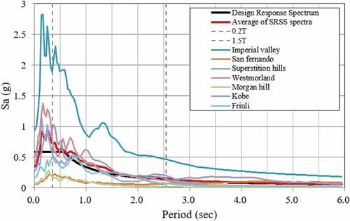
Table 4. Seismic load.
Table 5. List of ground motions for selected earthquakes.
3. Analysis results of the proposed modeling method
The results of modal analysis were compared between detailed models and simplified models using MIDAS Gen structural analysis software. The fundamental periods of numerical models are summarized in . According to modal analysis, it was confirmed that the difference of fundamental periods between simplified model and detailed models in Group 1 and Group 2 was about 11%. The presence of higher mode effect is presented as shown in . According to the ASCE 41 criterion (ASCE Citation2017), To determine if higher mode effects are significant, a modal analysis shall be performed for the structure using sufficient modes to produce 90% mass participation, and then modal analysis shall also be performed, considering only the first mode participation. Higher mode effects shall be considered significant if the shear force in any story resulting from the modal analysis considering modes required to obtain 90% mass participation exceeds 130% of the corresponding story shear considering only the first mode response. In this study, the results of modal analysis were similar in the X direction and the Y direction; the result of the X direction is shown in as a representative. The shear ratio referred to the ratio between story shear when considering 90% mass participation and story shear when considering only the first mode. The analysis results in Group 1 confirmed that SS-1 and ST-1, which were vertical geometric irregularity structures, showed a story shear ratio of more than 130% above the sixth floor, and approximate model, SM-1 showed a story shear force ratio of more than 130% above the seventh floor. The analysis results in Group 2 confirmed that the SM-2, SS-2 and ST-2 models had a story shear force ratio of more than 130% on the first floor and above the sixth floor. The effect of higher modes is significant if the story shear force ratio exceeds 130% in any story, so all numerical models had a dominant effect from higher modes. Since the higher mode effect was related to the torsional effect of the structures, it is confirmed that the proposed modeling method can show approximately the torsional behavior of the vertically irregular structures.
Figure 8. Checking for the presence of higher mode effects in numerical models: (a) Group 1. (b) Group 2.
Table 6. Comparison of fundamental periods between detailed models and simplified model.
The nonlinear dynamic analysis was conducted to compare dynamic behavior between simplified model and detailed model. Since seven ground motions were used for the nonlinear dynamic analysis, a total of fourteen results were derived for each analysis, and these results were averaged for analysis. In all numerical models, the analysis was terminated with all column members showing the level of collapse prevention (CP) on the first floor. The deformations of each numerical model investigated through nonlinear dynamic analysis are shown in . indicates the deformations of Group 1 as a representative. The comparisons of story shear and story drift between simplified models and detailed models are shown in . In the case of Group 1, the differences of story shear between SM-1 and SS-1, ST-1 were about 12%, and 13%. In addition, the differences of story drift were about 18%, and 23%. In the case of Group 2, the differences of story shear between SM-2 and SS-2, ST-2 were about 20%, and 17%. In addition, the differences of story drift were about 30%, and 28%. This analysis results demonstrated that the simplified method can estimate results such as story shear and story drift of vertically irregular structures. In addition, the current design code such as ACI 318 (ACI Citation2019) and ASCE (Citation2017) determine irregularity of structures too simple way. Therefore, even irregular structures can be evaluated as regular structures, which can lead to errors in analysis. Since the proposed method does not change in the analysis method even if it is evaluated as regular or irregular, practical engineers can be obtained approximate results without analysis errors at the initial stage.
Figure 9. Deformation of specimens. (a) SM-1. (b) SS-1. (c) ST-1.
Figure 10. Comparison of dynamic analysis results. (a) Story shear of group 1. (b) Story drift of group 1. (c) Story shear of group 2. (d) Story drift of group 2.
4. Conclusions
In this paper, the simplified modeling method for vertically irregular structures was proposed. The simplified modeling method allows estimating nonlinear dynamic results such as story shear and story drift for dynamic assessment of vertically irregular structures. This method is about converting vertically irregular structure to geometrically regular structure with calculating story stiffness. The nonlinear dynamic analysis and modal analysis were performed to evaluate the validity of the proposed modeling method. The following conclusions were drawn from this study:
As a result of modal analysis, it was confirmed that the difference of fundamental periods between simplified models and detailed models was about 11%. In addition, the higher mode effects were significant in all numerical models with showing similar differences in shear force in each story. Since the higher mode effect was related to the torsional effect of the structures, it is confirmed that the proposed modeling method can represent the torsional behavior of the vertically irregular structures modeled in detail.
The nonlinear dynamic analysis was conducted to compare dynamic behavior between the simplified model and detailed model. In all numerical models, the analysis was terminated with all column members showing the level of collapse prevention (CP) on the first floor. The differences of story shear and story drift were about 15% and 24%, respectively.
The simplified modeling method can estimate story shear and story drift of vertically irregular structures approximately, but the results are not close to the exact solution. The purpose of proposed method is to provide a method that enables to evaluate vertical irregularity simply and quickly in practice. Therefore, this simplified method would be helpful for practical engineers at initial structural design stages which need to save time. To confirm the applicability to various types of vertically irregular structures, more experimental and analytical studies are needed.
Acknowledgments
This work was supported by a National Research Foundation of Korea (NRF) grant funded by the Korean government (MSIT) (No. 2020R1A2C2009351).
Disclosure statement
No potential conflict of interest was reported by the author(s).
Additional information
Funding
Notes on contributors
Kyoung Min Ro
Kyong Min Ro is a Ph.D. Candidate in the Department of Architectural Engineering, Kyoung Hee University.
Min Sook Kim
Min Sook Kim is a Research Fellow in the Department of Architectural Engineering, Kyoung Hee University.
Young Hak Lee
Young Hak Lee is a Professor in the Department of Architectural Engineering, Kyoung Hee University.
References
- Abbasnia, R., A. T. Davoudi, and M. M. Maddah. 2013. “An Adaptive Pushover Procedure Based on Effective Modal Mass Combination Rule.” Engineering Structures 52: 654–666. doi:10.1016/j.engstruct.2013.03.029.
- ACI. 2019. ACI 318-19: Building Code Requirements for Structural Concrete and Commentary. Farmington Hills, MI: American Concrete Institute.
- ASCE. 2017. ASCE/SEI 41-17: Seismic Evaluation and Retrofit of Existing Buildings. Reston, Virginia, USA: American Society of Civil Engineers.
- Aşıkoğlu, A., G. Vasconcelos, P. B. Lourenço, and B. Pantò. 2020. “Pushover Analysis of Unreinforced Irregular Masonry Buildings: Lessons from Different Modeling Approaches.” Engineering Structures 218: 1–20. Article ID 110830. doi:10.1016/j.engstruct.2020.110830.
- Azizi-Bondarabadi, H., N. Mendes, and P. B. Lourenço. 2019. “Higher Mode Effects in Pushover Analysis of Irregular Masonry Buildings.” Journal of Earthquake Engineering 25(8): 1–35.
- Bhandari, M., S. D. Bharti, M. K. Shrimali, and T. K. Datta. 2018. “Assessment of Proposed Lateral Load Patterns in Pushover Analysis for Base-isolated Frames.” Engineering Structures 175: 531–548. doi:10.1016/j.engstruct.2018.08.080.
- Bhosale, A. S., R. Davis, and P. Sarkar. 2017. “Vertical Irregularity of Buildings: Regularity Index versus Seismic Risk.” ASCE-ASME Journal of Risk and Uncertainty in Engineering Systems, Part A: Civil Engineering 3 (3): 1-10.
- Cancellara, D., and F. De Angelis. 2017. “Assessment and Dynamic Nonlinear Analysis of Different Base Isolation Systems for a Multi-storey RC Building Irregular in Plan.” Computers & Structures 180: 74–88. doi:10.1016/j.compstruc.2016.02.012.
- Cancellara, D., and F. De Angelis. 2019. “Dynamic Assessment of Base Isolation Systems for Irregular in Plan Structures: Response Spectrum Analysis Vs Nonlinear Analysis.” Composite Structures 215: 98–115. doi:10.1016/j.compstruct.2019.02.013.
- Center, PEER. 2021. PEER Ground Motion Database. University of California, Berkeley, USA: Pacific Earthquake Engineering Research Center. http://ngawest2.Berkeley.edu
- Chopra, A. K., and R. K. Goel. 2002. “A Modal Pushover Analysis Procedure for Estimating Seismic Demands for Buildings.” Earthquake Engineering & Structural Dynamics 31 (3): 561–582. doi:10.1002/eqe.144.
- CSI. 2011. PERFORM Components and Elements for PERFORM‐3D and PERFORMCOLLAPSE. Berkeley, California, USA: Computers and Structures, Inc.
- Das, P. K., S. C. Dutta, and T. K. Datta. 2021. “Seismic Behavior of Plan and Vertically Irregular Structures: State of Art and Future Challenges.” Natural Hazards Review 22 (2): 4020062. doi:10.1061/(ASCE)NH.1527-6996.0000440.
- Esfahanian, A., and A. A. Aghakouchak. 2019. “A Single-run Dynamic-based Approach for Pushover Analysis of Structures Subjected to Near-fault Pulse-like Ground Motions.” Journal of Earthquake Engineering 23 (5): 725–749. doi:10.1080/13632469.2017.1326420.
- Khaloo, A. R., H. Masoomi, S. Nozhati, and M. M. Dehcheshmeh. 2016. “Influence of Diaphragm Opening on Seismic Response of Rectangular RC Buildings with End Shear Walls.” Scientia Iranica 23 (4): 1689–1698. doi:10.24200/sci.2016.2239.
- Kreslin, M., and P. Fajfar. 2011. “The Extended N2 Method Taking into Account Higher Mode Effects in Elevation.” Earthquake Engineering & Structural Dynamics 40 (14): 1571–1589. doi:10.1002/eqe.1104.
- KSCS. 2019. KDS 41 17 00: Seismic Design of Buildings. Seoul, Republic of Korea: Korea Construction Standards Center.
- Kumar, R., and D. R. Sahoo. 2021. “Seismic Fragility of Steel Special Truss Moment Frames with Multiple Ductile Vierendeel Panels.” Soil Dynamics and Earthquake Engineering 143: 106603. Article ID 106603. doi:10.1016/j.soildyn.2021.106603.
- Marino, S., S. Cattari, and S. Lagomarsino. 2019. “Are the Nonlinear Static Procedures Feasible for the Seismic Assessment of Irregular Existing Masonry Buildings?” Engineering Structures 200: 1–16. Article ID 109700. doi:10.1016/j.engstruct.2019.109700.
- Mazza, F., M. Mazza, and A. Vulcano. 2015. “Displacement-based Seismic Design of Hysteretic Damped Braces for Retrofitting In-elevation Irregular Rc Framed Structures.” Soil Dynamics and Earthquake Engineering 69: 115–124. doi:10.1016/j.soildyn.2014.10.029.
- Moehle, J. P. 1984. “Seismic Response of Vertically Irregular Structures.” Journal of Structural Engineering 110 (9): 2002–2014. doi:10.1061/(ASCE)0733-9445(1984)110:9(2002).
- Oyguc, R., C. Toros, and A. E. Abdelnaby. 2018. “Seismic Behavior of Irregular Reinforced-concrete Structures under Multiple Earthquake Excitations.” Soil Dynamics and Earthquake Engineering 104: 15–32. doi:10.1016/j.soildyn.2017.10.002.
- Poursha, M., F. Khoshnoudian, and A. S. Moghadam. 2009. “A Consecutive Modal Pushover Procedure for Estimating the Seismic Demands of Tall Buildings.” Engineering Structures 31 (2): 591–599. doi:10.1016/j.engstruct.2008.10.009.
- Poursha, M., F. Khoshnoudian, and A. S. Moghadam. 2014. “The Extended Consecutive Modal Pushover Procedure for Estimating the Seismic Demands of Two-way Unsymmetric-plan Tall Buildings under Influence of Two Horizontal Components of Ground Motions.” Soil Dynamics and Earthquake Engineering 63: 162–173. doi:10.1016/j.soildyn.2014.02.001.
- Sarkar, P., A. M. Prasad, and D. Menon. 2010. “Vertical Geometric Irregularity in Stepped Building Frames.” Engineering Structures 32 (8): 2175–2182. doi:10.1016/j.engstruct.2010.03.020.
- Schultz, A. E. 1992. “Approximating Lateral Stiffness of Stories in Elastic Frames.” Journal of Structural Engineering 118 (1): 243–263. doi:10.1061/(ASCE)0733-9445(1992)118:1(243).
- Shakeri, K., M. A. Shayanfar, and T. Kabeyasawa. 2010. “A Story Shear-based Adaptive Pushover Procedure for Estimating Seismic Demands of Buildings.” Engineering Structures 32 (1): 174–183. doi:10.1016/j.engstruct.2009.09.004.
- Shojaei, F., and B. Behnam. 2017. “Seismic Vulnerability Assessment of Low-rise Irregular Reinforced Concrete Structures Using Cumulative Damage Index.” Advances in Concrete Construction 5 (4): 407-422.
- Structural Engineering Institute. 2016. ASCE/SEI 7-16: Minimum Design Loads for Buildings and Other Structures. Reston, Virginia,USA: American Society of Civil Engineers.