
ABSTRACT
An excavator is a representative construction machine used to perform earthwork. The work efficiency of an excavator significantly influences the overall work productivity of the earthwork. However, the work efficiencies of the excavators reduce with the increasing shortage of skilled excavator drivers. This study aims to develop a vision-based machine guidance system for excavators that can be used in earthwork sites to improve the work safety and efficiency of the operation. The prototype of the vision-based machine guidance system developed in this study had an around-view monitoring (AVM) image radius of 7 m. The information is updated every 50 ms, and the AVM images are refreshed at an average rate of 28.2 fps, thereby improving the efficiency of the actual excavation. The performance and stability of the developed prototype were verified through 80 h of continuous field operation. In this study, field testing was conducted on one excavator driver. Hence, further work is necessary to quantitatively verify the system using many excavator drivers. The system can improve the work efficiency after its commercialization, in comparison to that of conventional earthwork using excavators. It allows the drivers to perform earthwork with improved safety and a full view around the excavator.
1. Introduction
Earthwork is a major construction activity that accounts for the highest share in the construction industry in South Korea (11.4 %) after reinforced concrete activities (20.4 %), mechanical equipment activities (16.2 %), and interior construction activities (11.8 %). It consists of large-scale construction projects with contracts in excess of $8,000,000,000 per year (Korea Specialty Contractors Association (KOSCA) Citation2020). Since earthwork is relatively more dependent on construction equipment than other types of construction (Lee et al. Citation2013), it is a labor-intensive process wherein the work productivity depends on the equipment operation skills and site adaptation of the deployed equipment operator (Kim and Seo Citation2011).
Excavators account for the maximum share (30.47 %) of the construction equipment registered in South Korea (Korea Construction Equipment Association (KCEA) Citation2020) that are used for earthwork. They are used for various types of earthwork, such as embankments, landfills, loading, compaction, and ground leveling. They have complex driving characteristics because they are composed of various working devices such as an undercarriage, a swing, a boom, an arm, and a bucket. Owing to the complexity caused by such devices, the driver’s field of view is limited, making it difficult for drivers to grasp the progress of work in real time; consequently, the safety and efficiency of work are heavily dependent on the proficiency of the driver. Therefore, simplifying the operation of these excavators, in addition to improving their convenience, will improve the safety and efficiency of the excavator operation and the productivity of the overall earthwork.
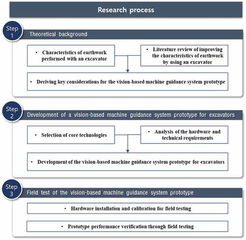
This study proposes the development of a vision-based machine guidance system for excavators that can simultaneously provide information on the excavator operation and a full view of the equipment to the driver, thereby improving the safety, efficiency, convenience, and simplicity of the excavator operation. It also verifies the performance of the system through field testing. The procedure is shown in . The successful commercialization and application of these results are expected to improve work efficiency by improving the convenience of the operation, which allows the drivers to perform earthwork safely, monitor the work status without blind spots, and minimize the risk of accidents during the operation.
Figure 1. Research process.
2. Theoretical background
2.1. Characteristics of earthwork performed with an excavator
Earthwork refers to the construction of a structure using soil as a material or creating a foundation (Kim, Jung, and Lee Citation2019). Earthwork requires various types of equipment, which depend on the environmental conditions and work methods (Moon and Cho Citation2015). The parameters that quantify work performance, such as productivity and quality, vary according to the utilization and operation skills of the equipment operator (Lee et al. Citation2013) owing to the high dependence on construction equipment.
An excavator consists of an undercarriage that moves the equipment, a swing that is mounted on the undercarriage and can perform 360° rotation, a boom, an arm, and a bucket. Thus, its driving characteristics are more complex than those of other construction equipment. These driving characteristics lead to the following operational difficulties.
2.1.1. High operational difficulty
The operation of an excavator requires accurate manipulation of the undercarriage and swing according to the condition of the ground, location of the surrounding structures, and work details. A decline in the influx rate of young excavator drivers at construction sites (Lee, Choi, and Park Citation2009) due to this high level of difficulty in excavator operation and the recent lack of skilled excavator drivers is rising as the main factors decreasing the efficiency of excavator-related operations and increasing the workplace accident rates.
2.1.2. Limited field of view due to blind spots
The excavator driver cannot be seated in the center of the equipment owing to the structural characteristics of the equipment, which includes a boom, an arm, and a bucket. Thus, the remaining areas, barring the left and front views, are blind spots for the driver. Such blind spots occur at a rate of approximately 41% (Teizer, Allread, and Mantripragada Citation2010), such a limited field of view makes it difficult for the excavator driver to grasp the operation status of the equipment immediately and work quickly according to the obtained information, thereby reducing the overall efficiency of the excavator operation.
2.1.3. Difficulty in judging the progress of the excavation
The excavator driver has to conduct the operation according to the pre-planned work area and excavation depth (Park et al. Citation2021); however, it is difficult to accurately grasp the progress of the operation at every instant in the excavator cabin. Therefore, the driver judges the situation according to their intuition or the number of signals around, leading to frequent construction errors. Erratic judgment from the driver, in addition to communication problems with the signal operator, may reduce the work efficiency.
Therefore, technical alternatives that can improve the convenience of the operation and simplify it by reducing the difficulty of the excavator operation and providing a relatively wide field of view are needed. Such technical alternatives can improve the overall excavation productivity by reducing the dependence on the skills of the excavator driver. This addresses the recent problem regarding the lack of skilled drivers and minimizes the deviation in work efficiency between excavator operators.
2.2. Literature review
This section analyzes previous studies that attempted to improve the characteristics of earthwork by using an excavator. These studies aimed to improve the work efficiency of excavators and are classified into two categories: studies that replaced the operator and studies that assisted the operator (Kim and Koo Citation2010).
2.2.1. Studies based on the replacement of the operator
These studies proposed the development of a fully automated unmanned excavator as an alternative to address the aging of the excavator drivers and the reduction in productivity due to a lack of skilled excavator drivers. A fully automated, unmanned excavation system that autonomously performed a series of processes, such as driving, local area 3D modeling, excavation planning, embankment, truck recognition, and loading, was developed by the Carnegie Mellon University (CMU), U.S., in the late 1990s. An intelligent excavation system (IES), equipped with a global 3D modeling and intelligent task planning system for an entire earthwork site, in addition to the functions of the CMU autonomous excavator (), was developed in South Korea.
Table 1. Previous studies based on the replacement of the operator.
A fully automated unmanned excavator can be used to improve the efficiency of excavation work, in addition to the quality and work productivity, irrespective of the skill level of the operator. It is useful in an extreme environment wherein it is difficult to deploy an operator.
A complete work plan of the construction project is required to utilize a fully automated unmanned excavator. However, parameters such as the ground height, design height, and work height must be constantly updated for a fully automated unmanned excavator to function efficiently. Further, changes in the design height, which are inevitable because of the varying construction environment, halt the excavation until the design height is changed in the excavator. Owing to these shortcomings, the application of a fully automated unmanned excavator system is impractical at all construction sites in the current technological environment. Therefore, studies have deviated from the development of a fully automated unmanned excavator technology to the development of technologies that can assist the operator by effectively improving the convenience and ease of the excavation.
2.2.2. Studies based on assistance to the operator
These studies focus on the development of a technique that improves the convenience and simplicity of the operation for the excavator driver. Studies based on providing assistance to the operator have been actively conducted since the mid-2000s. These technologies have recently been commercialized and utilized in the construction field ().
Table 2. Previous studies based on providing assistance to the operator.
Most studies based on providing assistance to the operator aim to improve the efficiency of the excavator operation by reducing the fear of accidents (such as collisions and structures) that are always present in the minds of the excavator drivers. However, these technologies have been unable to adequately assist the operation of an actual excavator because they only aim to prevent collisions with obstacles and laborers.
Cho et al. (Citation2016) used image information, i.e., the information obtained from the field of view, to construct an excavator approach detection system. However, the application of this information was limited because the original image that contained the distortion acquired from the camera did not present any information to assist the operation, besides preventing collisions between the excavator and workers.
2.3. Key considerations for the vision-based machine guidance system prototype
This section identifies the key considerations for the development of the vision-based machine guidance system prototype for excavators. In-person interviews (Seo et al. Citation2018) were conducted with 10 drivers experienced in conducting excavator operations. The information required to improve excavation work efficiency, which was based on these interviews, was analyzed in terms of driving, on-site movement, and excavation work. The interviews involved excavator drivers with varying degrees of experience. They included three drivers with less than three years of experience, one driver with four to six years of experience, two drivers with seven to nine years of experience, and four drivers with more than 10 years of experience.
2.3.1. Driving
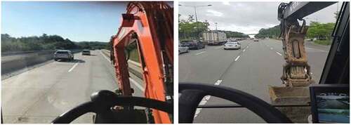
The field of view while driving an excavator is insufficient even for a drive on a paved road because of the blind spots in the sides and rear of the equipment (). Thus, the operation efficiency is hindered by the difficulty of the equipment operation, and there is an inherent risk of accidents, such as collisions and falls. The interviews of the excavator drivers indicated that the blind spots made it difficult for them to comprehend the status of the surroundings. In particular, the drivers with less than three years of experience felt overwhelmed by the excavator operation, even while driving on pavement. Most of the interviewed excavator drivers selected the around-view monitoring (AVM) system as the optimal technical supplement to provide assistance while driving an excavator.
Figure 2. Field of view of the driver while operating the excavator on the pavement.
2.3.2. On-site movement
There are various obstacles at the construction sites where excavation occurs, such as laborers, equipment, materials, and structures. Thus, it is very difficult to move an excavator around the site ().
Figure 3. On-site environment for the movement of an excavator.
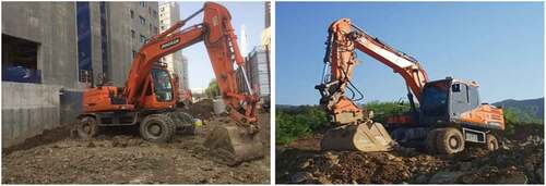
It is difficult for an excavator driver to objectively determine the current status of an excavator because it has complex driving characteristics in comparison to those of general vehicle-type equipment, due to the operations of the boom, arm, bucket, and swing. The excavator drivers stated in their interviews that the relationship between the current state of the excavator and the surrounding terrain should be evaluated from a third-person perspective to ensure that the excavator is operated proficiently with a varying radius that depends on the operation of the boom, arm, and bucket. Thus, the work efficiency can be increased only if the current status of the excavator and the surrounding obstacles and workers are intuitively determined while moving in the field.
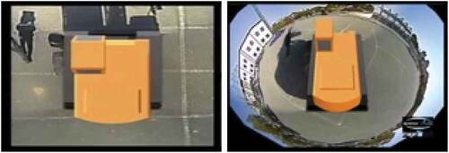
The application of the existing AVM system for excavators () was limited to driving because the displayed area was narrow (within 4–5 m), and an image captured at a long distance from the excavator was highly distorted. Since the existing system utilized existing vehicle-type technology without any modifications, the operation characteristics (boom, arm, bucket, etc.), other than the body of the excavator, were not reflected in the AVM image. In addition, the distortion of the AVM image increased significantly if the body of the excavator is tilted because it was designed to be used on pavement.
Figure 4. Existing AVM system for excavators.
2.3.3. Excavation work
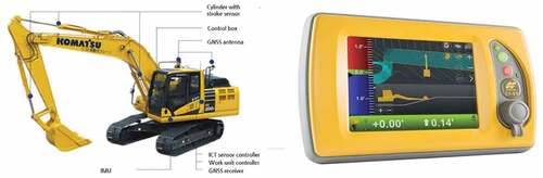
Several machine guidance technologies have recently been developed to improve the efficiency of excavator operation (). A previous study (Yoon et al. Citation2016) reported a 40.4 % reduction in the time taken to complete earthwork when an amateur driver with less than one year of experience used a machine guidance system. The excavator drivers reported that the greatest advantage of the machine guidance technology for the excavators was that it enabled highly accurate monitoring of the work status, especially by providing information such as the current excavator bucket depth and the current inclination and posture of the excavator – factors that cannot be easily determined from the display in front of the driver’s seat. However, the installation of the machine guidance system on the excavator is very expensive. Its utilization and on-site applicability are limited because there are frequent mismatches between the actual ground environment and the drawings provided by the machine guidance system. In addition, it could be impossible to perform the operation by relying solely on the display because peripheral-vision information was not provided on the machine guidance screen.
Figure 5. Existing machine guidance system for excavators.
3. Development of a vision-based machine guidance system prototype for excavators
The system design process of a vision-based machine guidance system is conducted by first selecting core technologies based on key considerations derived in section 2.3. Then, the hardware and technical requirements are analyzed to implement the core technologies. In the study, a vision-based machine guidance system is developed based on the system design.
3.1. Selection of core technologies for a vision-based machine guidance system prototype
Based on key considerations, the core technology of the vision-based machine guidance system prototype was selected as the AVM technology for the excavators, the excavator work information display technology, and the image correction technology based on the excavator inclination ().
Figure 6. Core technologies of the vision-based machine guidance system prototype for excavators.
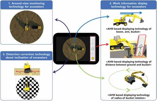
3.1.1. AVM technology for excavators
The AVM technology for excavators was an upgrade to the original technology of the existing AVM system (), which was developed for commercial vehicles. The existing technology was not applied to the vision-based machine guidance system prototype in this study; instead, a 2D AVM module, which was suited to the excavator specifications and accurately displayed the distance information, was developed and applied.
3.1.2. Excavator work information display technology
The proposed excavator work information display technology was also an upgrade to the existing machine guidance system for excavators (), which consisted of expensive hardware and displayed the work status in a virtual environment. An augmented reality (AR) version of the work information was displayed on a real-time image obtained from the AVM technology for excavators in the proposed vision-based machine guidance system instead of displaying the information in a virtual environment. The results of the interviews of the excavator drivers were used to display the essential work information for the excavator operation. This information was classified into three categories according to its source: the AVM-based boom, arm, and bucket display technology; the AVM-based ground-bucket separation distance display technology; and the AVM-based bucket rotation radius display technology.
3.1.3. Image correction technology based on the inclination of the excavator
The floor surface of a construction site where an excavator is operated, unlike that of a pavement, is highly uneven. Thus, the excavator cannot maintain a horizontal inclination to the ground. Since the AVM converts the image acquired through a camera installed on four sides of the excavator into a top-view perspective, the AVM image is highly distorted. Thus, the application of AVM images in providing assistance for the operation is extremely limited. The image correction technology proposed in this study was designed to address these shortcomings by correcting the distortion of the AVM image caused by the actual inclination of the excavator by utilizing the inclination information of the excavator. The proposed technology assisted the drivers in accurately recognizing the working environment around the excavator, thereby improving the safety and efficiency of the overall excavation.
3.2. Analysis of the hardware and technical requirements
3.2.1. AVM technology for excavators
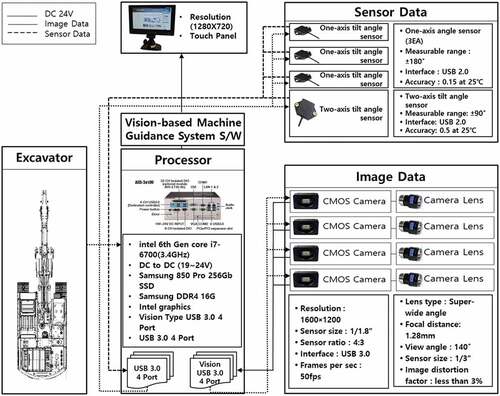
The hardware required to apply the AVM technology for excavators consists of three components: a camera (CMOS sensor) for image acquisition, an ultra-wide-angle lens with a minimum field of view of 140° or a fish-eye lens with a minimum field of view of 180° to capture the image area, and a quad-core processor or a processor with additional CPUs for image processing. The existing AVM system, which was originally designed for commercial vehicles, is limited to a top-view range of 4–5 m. However, the AVM technology for excavators developed in this study had a top-view range within 7 m, which is equal to the normal working radius of small and medium-sized excavators. In addition, the AVM technology for excavators was utilized in real time by updating the image converted to AVM at a refresh rate of at least 15 fps (Hosseini and Georganas Citation2003).
3.2.2. Excavator work information display technology
The excavator work information display technologies (the AVM-based boom, arm, and bucket display technology; the AVM-based ground-bucket separation distance display technology; and the AVM-based bucket rotation radius display technology) were related to the operational characteristics of the excavators in terms of the movement of the boom, arm, and bucket. Information related to the movement of the excavator boom, arm, and bucket is required to utilize the proposed excavator work information display technology. A one-axis tilt angle sensor was installed on the boom, arm, and bucket of the excavator to obtain the positional information of the boom, arm, and bucket through the global navigation satellite system (GNSS). The one-axis tilt angle sensor is compact; thus, it is relatively easy to select a location for its installation. Further, the boom, arm, and bucket positions calculated by the sensor were more accurate and reliable than those obtained using previous techniques.
3.2.3. Image correction technology according to the inclination of the excavator
It is essential to obtain information on the inclination of the excavator to apply the image correction technology. The inclination of the excavator is expressed in the body-fixed reference frame, and angular information on the roll and pitch is required to apply the image correction technology. Machine guidance equipment based on GNSS and inertial measurement units are currently being used to obtain information on the roll, pitch, and yaw angles of an excavator in the field. Since the roll and pitch angles can be obtained with a two-axis tilt sensor, the vision-based machine guidance system prototype for excavators used a two-axis tilt sensor instead of the expensive GNSS equipment, thereby reducing the cost of the equipment.
The final hardware of the vision-based machine guidance system prototype for excavators, which satisfied the abovementioned hardware and technical requirements, was selected and designed as shown in .
Figure 7. Final hardware design for the vision-based machine guidance system prototype for excavators.
3.3. Development of the vision-based machine guidance system software
The software of the vision-based machine guidance system prototype for the excavators was developed on Microsoft Visual C++ 2013, API/MFC. The image field was developed primarily using the OpenCV and OpenGL libraries, and the u-Nova SDK was used to control the cameras (USB 3.0 u-Nova20c).
3.3.1. Development of AVM algorithm for excavator
The AVM algorithm process for an excavator is shown in . In addition, the AVM algorithm is divided into a warp map module and an AVM generation module ().
Figure 8. Process of composing an AVM image.
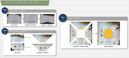
Figure 9. Configuration of the AVM algorithm.
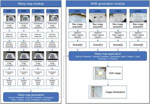
The AVM algorithm starts with the stable control of images from four cameras. The 3D spatial coordinates are restored by geometrically considering various factors, such as the location and direction, of each 2D image. The homography matrix can explain the 2D image conversion relationship of a planar object. A top view is created by converting the viewing angle of the original image to the floor through a perspective transformation using a homography matrix.
After the top view conversion, all images are displayed in the north direction, and the scales of each image are different. The Affine Transform module includes the processes of rotating, zooming, and moving (rotation, scaling, moving), considering the factors such as the height and angle of the cameras. At this time, if the operation is repeated every frame for each camera, the CPU resource is excessively used, so a high-speed module has been developed. This module calculates the entire process only once and saves the result in memory. Finally, an interpolation algorithm was applied to compensate for the loss of pixels that occurs in the AVM conversion.
3.3.2. Development of expressing work information algorithm for excavator
The coordinates for the representation of the boom, arm, and bucket in the AVM image are calculated as shown in .
Figure 10. Expressing work information technology for excavator.
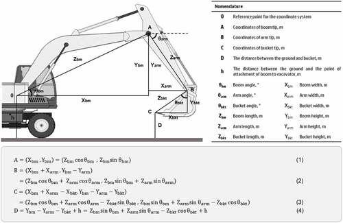
The technology calculates the relative coordinates of a point (A) where a boom and an arm are connected, a point (B) where an arm and a bucket are connected, and the end of a bucket point (C), and the vertical distance (D) from the ground to the end of the bucket.
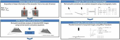
3.3.3. Development of image correction algorithm according to excavator inclination
If excavators are operated at uneven earthwork and construction sites, the image acquisition area changes depending on the slope of the excavator in the AVM image. Accordingly, the excavator driver causes an error when determining whether the object on the AVM screen is closer or farther than the actual location. The algorithm process to improve this was developed as shown in .
Figure 11. Image correction algorithm according to excavator inclination.
3.4. Development of the vision-based machine guidance system prototype for excavators
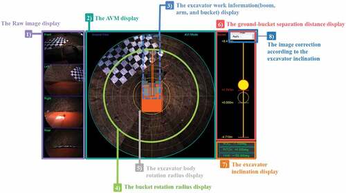
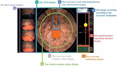
The development of the vision-based machine guidance system prototype for excavators was split into the following eight modules.
1) The raw image display;
2) The AVM display;
3) The excavator work information (boom, arm, and bucket) display;
4) The bucket rotation radius display;
5) The excavator body rotation radius display;
6) The ground-bucket separation distance display;
7) The excavator inclination display;
8) The image correction according to the excavator inclination, as shown in ().
Figure 12. Vision-based machine guidance system prototype for excavators.
3.4.1. Raw image display (-1)
This module displays the images acquired from the front, left, right, and rear cameras installed in the excavator in real time, in that order. Users can enlarge and use one image in full screen if necessary. The full-screen function can be enabled and disabled by selecting the corresponding image. In addition, raw images were captured in the storage device by using a recording module.
3.4.2. AVM display (-2)
This module displayed an image with a minimum radius of 7 m around the excavator in a 2D top view. The users can utilize this module to optimize the AVM image according to the specifications of the excavator and the installed position of the camera. This provides the user with several features, such as vignetting options, grid settings, automatic image exposure adjustment, and AVI mode.
3.4.3. Excavator work information (boom, arm, and bucket) display (-3)
This module displays the real-time status of the boom, arm, and bucket in 2D on the AVM display. The initial values must be entered according to the specifications of the excavator before using this module to display the boom, arm, and bucket work information.
3.4.4. Bucket rotation radius display (-4)
This module displays the radius at which the bucket of the excavator rotates in the AVM image. The endpoint and central point of the circle drawn at this instant represent the endpoint of the bucket and the center of rotation of the excavator, respectively. The driver is expected to be able to perform tasks, such as loading, efficiently with improved work safety by using this real-time function.
3.4.5. Excavator body rotation radius display (-5)
This module displays the radius at which the body of the excavator rotates in the AVM image. The endpoint of the circle drawn at this instant is the farthest point from the center of the excavator, in comparison to the corners of the excavator.
3.4.6. The ground-bucket separation distance display (-6)
This module displays the separation distance between the ground on which the excavator is resting and the tip of the bucket. The maximum height and depth from the ground prior to the application of this module was calculated and entered in the settings according to the specifications of the excavator. This information was then used to display the real-time position according to the movement of the boom, arm, and bucket.
3.4.7. Excavator inclination display (-7)
The inclination of the excavator is expressed in a body-fixed reference frame (roll, pitch, and yaw).
3.4.8. Image correction module according to excavator inclination display (-8)
This module corrects images according to the inclination of the excavator. If the excavator is tilted on an uneven surface, this module generates a function to correct the image automatically.
4. Field test of the prototype
4.1. Hardware installation and calibration for field testing
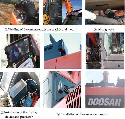
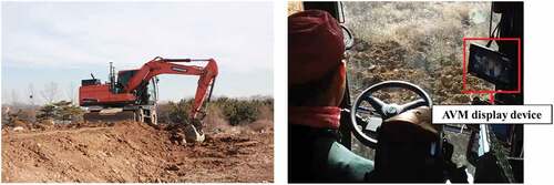
The hardware was installed and calibrated through field tests of the vision-based machine guidance system prototype for excavators. The hardware was installed in the following order.
1) Welding of the camera enclosure bracket and mount;
2) Wiring work;
3) Installation of the AVM display device and processor;
4) Installation of the camera and sensor ().
Figure 13. Hardware installation for the vision-based machine guidance system prototype for excavators.
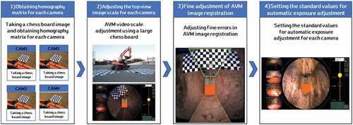
The prototype was calibrated after its installation to ensure smooth operation. The calibration was performed in the following order.
1) Procurement of a homography matrix for each camera;
2) Adjustment of the scale of the top-view image captured by a camera;
3) Fine adjustment of the AVM image registration;
4) Setting of a standard value for automatic exposure adjustment ().
Figure 14. Calibration process for the vision-based machine guidance system prototype for excavators.
4.2. Prototype performance verification through field testing
4.2.1. Performance verification of the prototype
Information related to the excavator construction site used for testing the performance of the prototype is presented in and . The performance of each module of the prototype was verified through the field test.
Figure 15. Excavation site used for testing the performance of the prototype.
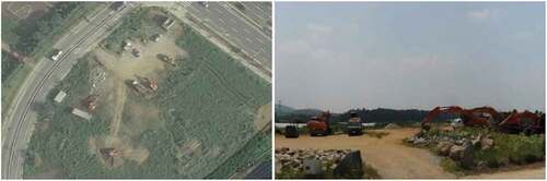
Table 3. Overview of the site used for testing the system performance.
1) Analysis of the appropriate AVM image area of the vision-based machine guidance system prototype for excavators
It is important to provide information on the excavator work area to the driver in the form of undistorted AVM images to improve the usability of the vision-based machine guidance system prototype for excavators. However, increasing the range of the raw images significantly distorts the displayed AVM image. Similarly, an increment in the angle of the camera to increase the AVM display area intensifies the distortion in the AVM image.
Therefore, the area must be limited to maintain the quality of the AVM image obtained from the vision-based machine guidance system prototype for excavators. The K/f value of the camera and lens used in this study was approximately 11.02. Even if the camera was installed at an angle close to 90°, it would be possible to display an AVM image of the site with a radius of 7 m from the center of the equipment, which is the normal working radius of the excavator. The AVM images obtained by limiting the installation angle and fixing the camera according to the characteristics of each installation position are shown in .
Figure 16. AVM image of the excavation site with a radius of 7 m from the center of the equipment.
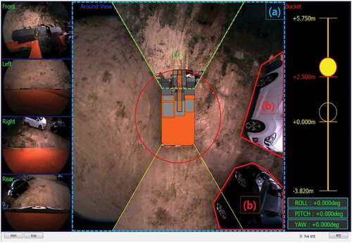
Thus, the prototype performed optimally in the AVM area within the 7 m radius, as shown in ). The distortion of the surrounding objects was significantly reduced, and it was possible to identify the objects in the image, as shown in ). In addition, the image loss of the front camera was prevented by adjusting its aperture and focus, as shown in ). Thus, by accounting for the top-view range of each camera, an area with a radius of 7 m was displayed as an AVM image in all cameras, and the average refresh rate for AVM images was 28.2 fps.
2) Analysis of the excavator work information display function
The excavator work information display function of the vision-based machine guidance system prototype for excavators was tested by examining whether the work information, which was acquired from the one-axis/two-axis tilt angle sensors installed on the boom, arm, bucket, and body of an actual excavator, was normally displayed on the AVM screen. The excavator work information display functions monitored the exact positions accurately according to the sensor information. The frequency at which the data acquired from the sensor was updated was equal to 50 ms. This frequency is suitable for real-time applications ().
Figure 17. Analysis of the excavator work information display.
3) Analysis of the image correction function according to the inclination of the excavator
The image correction function of the vision-based machine guidance system prototype for excavators, which was based on the inclination of the excavator, was tested by verifying whether it performed accurately during an actual inclination in an excavator. Thus, image correction was performed in real time during an actual inclination. The data acquired from the sensor were updated at a frequency of 50 ms.
4.2.2. Stability verification of the vision-based machine guidance system prototype for excavators through an 80-hour field operation
shows the site chosen to verify the stability of the vision-based machine guidance system prototype for excavators through long-term field operation. The excavation operations performed on the site included cutting, embankment, loading, temporary road construction, and drainage work. The field conditions permitted the active application of the developed prototype because the level of difficulty of the operation was high due to the presence of several hills, curved surfaces, and obstacles on the ground ().
Figure 18. Site chosen for system stability testing through long-term field operations.
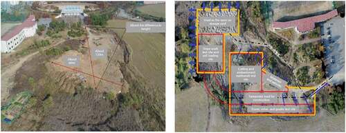
Table 4. Overview of the site for system stability testing through long-term field application.
1) Analysis of the long-term field operation of the vision-based machine guidance system prototype for excavators
A test was conducted by operating the prototype continuously for 8 h over 10 days to verify its system stability(). The hardware of the vision-based machine guidance system prototype for excavators was installed during the test without removal or disassembly, even after the completion of the operation. The system was continuously operated without any interruptions, thereby ensuring that a minimum continuous operation time of 80 h was achieved.
Figure 19. Long-term field operation of the vision-based machine guidance system prototype for excavators.
The system stability test confirmed that the developed prototype could be operated normally without any hardware defects at temperatures ranging from −10 °C to 10 °C. The prototype displayed stable performance during the 80-hour-long excavation without system errors.
2) User satisfaction survey of the vision-based machine guidance system prototype for excavators
The user satisfaction survey of the vision-based machine guidance system prototype for excavators involved excavator drivers that had operated this system for more than 80 h. The survey was conducted through face-to-face interviews. It was divided into four categories: convenience and ease of work, safety, quality of system development, and system utilization.
The survey indicated that the excavator drivers were extremely satisfied with the developed system. They confirmed that the system was particularly effective in terms of convenience, ease of work, and safety. The convenience and ease of work were significantly improved by the application of the prototype because the work information displayed in the system was very useful during the construction of waterways, pipelines, structures, urban regions, etc. The image correction function, which was based on the excavator inclination, permitted the excavator drivers to examine the ground around the excavator confidently, even in a tilted state. The safety of work was ensured while simultaneously improving the work efficiency because the environment around the excavator was visible to the excavator driver owing to the absence of blind spots. The excavator drivers rated the system stability very highly, confirming the quality of the developed system. The system utilization was also satisfactory because the system proved to be very useful while driving and performing excavations using an excavator. Thus, the system was very beneficial for novice excavator drivers.
5. Conclusion
A vision-based machine guidance system prototype for excavators was developed in this study to improve the efficiency of excavator operations. Its performance was verified through field testing. The vision-based machine guidance system prototype proposed in this study was developed for small and medium-sized excavators; however, the technology and methodology used in this study can assist the development of similar systems in different construction and civil engineering projects by accounting for the working characteristics of the construction equipment. The conclusions drawn from this study are listed below.
1) An analysis of the characteristics of the earthwork performed using an excavator indicated that there was a need to simplify excavator operations and provide visual field and work information to improve the excavator work efficiency. The viability of the fully automated unmanned excavator technologies and excavator collision prevention and obstacle detection technologies, which were previously developed to improve the work efficiency of excavators, was limited because of their negligible impact in terms of actual excavation assistance.
2) An investigation of the key considerations regarding the development of the vision-based machine guidance system prototype for excavators indicated that the assistance system should be capable of monitoring the status around the excavator while driving. It should be able to identify the positions of the boom, arm, and bucket of the excavator. Further, it should account for the on-site movement and the excavation work by displaying the depth of the excavator bucket and the excavator inclination and posture, respectively.
3) The core technologies selected for the vision-based machine guidance system prototype for excavators include the AVM technology for excavators, the excavator work information display technology, and the image correction technology, which is based on the excavator inclination. A CMOS sensor-based HD camera, an ultra-wide-angle lens or a fish-eye lens with a minimum field of view of 140° or 180°, a quad-core processor or a processor with additional CPUs, a one-axis tilt angle sensor with a minimum angular range of 180°, and a two-axis tilt sensor with a minimum angular range of 90° were required.
4) The results of the field test indicated that the prototype of the vision-based machine guidance system for excavators had an AVM image radius of 7 m and an average refresh rate of 28.2 fps for AVM images. The excavator work information display technology and the image correction technology, which was based on the excavator inclination, were operated in real time according to the information acquired from the sensors at a frequency of 50 ms. A system stability test was conducted wherein the developed prototype exhibited stable performance during 80 h of continuous operation. Thus, when the vision-based machine guidance system is applied to an excavator, safety accidents related to the collisions between the excavator and construction worker can be reduced. This is because the excavator driver can move around the construction site or perform excavation work without blind spots. In addition, the efficiency of earthworks is expected to increase because the workload of the excavator operator is reduced.
Despite this result, this study has limitations in that only one excavator driver used the developed vision-based machine guidance system. In the future, this system should be experienced by a number of excavator drivers, and the convenience, ease, and safety improvement effects of excavation work according to system use should be quantitatively verified.
The vision-based machine guidance system prototype for excavators developed in this study is the first work assistance system based on a combination of an excavator machine guidance system and an excavator AVM system. The constant rise in the application of construction equipment in construction and civil engineering projects, in addition to the enlargement, diversification, and complexity of the construction industry, has increased the future scope and effectiveness of the vision-based machine guidance system prototype for excavators. After the field applicability and technical/economic feasibility of the results of this study are validated, there is a very high possibility of cost reduction by increasing the efficiency of excavator operation and technology transfer in the technology market. In the first quarter of 2022, the developed excavator AVM system is to be applied for three construction sites in Korea for verifying its performance in terms of work efficiency, safety and ease of use, and overall evaluation results. Moreover, a survey for assessing its field applicability that targets a number of excavator drivers will be quantitatively and qualitatively presented in a future study.
Disclosure statement
No potential conflict of interest was reported by the author(s).
Additional information
Funding
Notes on contributors
Dong-Jun Yeom
Dong-Jun Yeom earned his Ph.D. in Construction Management in Department of Architectural Engineering in 2018 from Inha University. He worked for the Industrial Science and Technology Research Institute at Inha University for 2 years. He has given a series of lectures on computer-aided design, computer programming for engineering applications, construction information technologies and etc. at Inha University since 2015. He currently serves as a postdoctoral research engineer at the Korea Institute of Civil Engineering and Building Technology.
Hyun-Seok Yoo
Hyun-Seok Yoo earned his Ph.D. in Construction Management in Department of Architectural Engineering in 2012 from Inha University. He currently serves as an associate professor in the Department of Technology Education at Korea National University of Education. His research interests are in the area of construction information technologies, automation in construction and etc. He has conducted various research projects in terms of automation in construction: an Automated Pavement Crack Sealing Machine, an Intelligent Excavating System, and various applications of information technologies and automation in construction.
Jun-Sang Kim
Jun-Sang Kim earned his master’s in Construction Management in Department of Architectural Engineering in 2020 from Inha University. He is a Ph.D. student majoring in Construction Management at Inha University.
Young Suk Kim
Dr. Young Suk Kim earned his Ph.D. in Construction Engineering and Project Management in 1997 from the University of Texas at Austin. He has given a series of lectures on an execution of building work, construction management, time management, cost management, contract management, construction information technology, automation in construction and etc. at Inha University since 1999. He currently serves as a professor in Department of Architectural Engineering at Inha University and a chairman of University Development Commission at Korea Institute of Construction Engineering and Management. His research interests are in the areas of sustainable construction, cost and time management, engineering education, and automation in construction. He has conducted various research projects in terms of automation in construction: an Automated Pavement Crack Sealing Machine, Tele-operated Concrete Pipe Laying Manipulator in the Trenches, Automated Controller for Checking Verticality and Automated, an Intelligent Excavating System, etc.
References
- Cannon, H. N. 1999. “Extended Earthmoving with an Autonomous Excavator.” Master’s Thesis, Carnegie Mellon University, Pittsburgh, USA.
- Cho, B. W., Y. S. Lee, D. K. Kim, J. H. Kim, and P. H. Choi. 2016. “Image-based Proximity Warning System for Excavator of Construction Sites.” Journal of Korea Contents Association 16 (10): 588–597. doi:10.5392/JKCA.2016.16.10.588.
- Hosseini, M., and D. Georganas (2003), “Design of a Multi-sensor 3D Videoconferencing Application over an End System Multicast Protocol,” in Proceedings of the eleventh ACM international conference on Multimedia New York, USA, pp. 480–489.
- Ishimoto, H., and T. Tsubouchi 2013. “Stereo Vision Based Worker Detection System for Excavator,” in ISCARC. Proceedings of the International Symposium on Automation and Robotics in Construction and Mining 30: 1, Montreal, Canada
- Kim, S. K., and B. Koo. 2010. “A Path Generation Method considering the Work Behavior of Operators for an Intelligent Excavator.” Journal of the Korean Society of Civil Engineers 30 (4D): 433–443.
- Kim, J. H., and J. W. Seo. 2011. “BIM Based Intelligent Excavation System.” Journal of KIBIM 1 (1): 1–5. doi:10.12652/Ksce.2013.33.1.363.
- Kim, K. K., H. W. Jung, and B. W. Lee. 2019. Construction Machinery Heavy Equipment Engineering. Golden Bell: Seoul.
- Korea Construction Equipment Association (KCEA). 2020. “Construction Equipment Registration Status.” Accessed on 19 April 2021. http://kcea.or.kr/Source/ke/ke0101.htm
- Korea Specialty Contractors Association (KOSCA). 2020. “2020 Contract Performance by Contractor and Industry.” Accessed on 19 April 2021. http://www.kosca.or.kr/public/I0/I040601.asp?GBN=C&m_y=2019&area=38#
- Lee, K. J., Y. J. Choi, and T. K. Park 2009. “Studies on the Ways to Improve Usability of Construction Machinery for Production Efficiency.” Proceedings of Korea Institute of Construction Engineering and Management Annual Conference for Students Daejeon, Korea, pp. 112–116.
- Lee, S. S., J. H. Jang, C. W. Yoon, and J. W. Seo. 2013. “Development of the Local Area Design Module for Planning Automated Excavator Work at Operation Level.” Journal of the Korean Society of Civil Engineers 33 (1): 363–375. doi:10.12652/Ksce.2013.33.1.363.
- Marks, E. D., T. Cheng, and J. Teizer. 2013. “Laser Scanning for Safe Equipment Design that Increases Operator Visibility by Measuring Blind Spots.” Journal of Construction Engineering and Management 139 (8): 1006–1014. doi:10.1061/(ASCE)CO.1943-7862.0000690.
- Moon, S., and K. Cho. 2015. “Information Modeling for Construction Equipment Interface in Earthwork.” Journal of the Korean Society of Civil Engineers 35 (3): 699–706. doi:10.12652/Ksce.2015.35.3.0699.
- Nah, J., S. Lee, C. Kim, H. Sohn, and C. Kim. 2015. “Real-Time Vision-Based Proximity Detection for Improved Worker Safety in Construction Equipment Operation.” Proc. of Architectural Institute of Korea 35 (2): 31–32.
- Park, S., J. Kim, S. Lee, and J. Seo. 2021. “A Comparative Analysis of Automated Machine Guidance and Control Systems for Trench Excavation.” KSCE Journal of Civil Engineering 25 (11): 4065–4074. doi:10.1007/s12205-021-0159-x.
- Riaz, Z., D. J. Edwards, and A. Thorpe. 2006. “SightSafety: A Hybrid Information and Communication Technology System for Reducing Vehicle/Pedestrian Collisions.” Automation in Construction 15 (6): 719–728. doi:10.1016/j.autcon.2005.09.004.
- Seo, J. W., S. W. Moon, S. K. Kim, J. W. Park, D. E. Lee, C. W. Kim, D. H. Shin, and W. Y. Jung 2018. “Development of Construction Equipment Control and Smart Construction Technology Using ICT.” Accessed on 19 April 2021. https://www.kaia.re.kr/portal/landmark/readTskView.do?menuNo=200060&tskId=79689&yearCnt=1#none;
- Soh, J. Y., M. W. Kim, J. B. Lee, and C. H. Han. 2008. “Development of Core Technology for Object Detection in Excavation Work Using Laser Sensor.” Journal of the Korea Institute of Building Construction 8 (4): 71–77. doi:10.5345/JKIC.2008.8.4.071.
- Teizer, J., B. S. Allread, and U. Mantripragada. 2010. “Automating the Blind Spot Measurement of Construction Equipment.” Automation in Construction 19 (4): 491–501. doi:10.1016/j.autcon.2009.12.012.
- Wu, W., H. Yang, D. Chew, S. Yang, A. Gibb, and Q. Li. 2010. “Towards an Autonomous Real-Time Tracking System of Near-Miss Accidents on Construction Sites.” Automation in Construction 19 (2): 134–141. doi:10.1016/j.autcon.2009.11.017.
- Yamamoto, H., M. Moteki, H. Shao, T. Ootuki, H. Kanazawa, and Y. Tanaka 2009. “Basic Technology Toward Autonomous Hydraulic Excavator.” In 26th International Symposium on Automation and Robotics in Construction (ISARC 2009), Austin, USA.
- Yeom, D. J., H. S. Yoo, and Y. S. Kim. 2019. “3D Surround Local Sensing System H/W for Intelligent Excavation Robot (IES).” Journal of Asian Architecture and Building Engineering 18 (5): 439–456. doi:10.1080/13467581.2019.1679148.
- Yoon, J. S., S. S. Lee, S. H. Park, S. M. Lee, and J. W. Seo (2016), “Earthwork Test and Performance Evaluation Using Machine Guidance for Excavator,” in Proc. of KSCE 2016 Conf., pp. 21–22.