
 ?Mathematical formulae have been encoded as MathML and are displayed in this HTML version using MathJax in order to improve their display. Uncheck the box to turn MathJax off. This feature requires Javascript. Click on a formula to zoom.
ABSTRACT
This study proposes a fiber beam-column model that takes into account the anisotropy of wood and the embedment behavior of the rocking column to assess the impact of wood damage on the lateral performance of traditional Chinese timber structures. Subsequently, numerical analyses corresponding to a full-scale quasi-static test of a traditional Chinese timber framework are conducted to verify the accuracy of this fiber beam-column model. By considering factors such as residual deformation and wood decay in the column base, the degradation behavior of traditional Chinese timber structures can be evaluated. This study provides a foundation for discussing and further researching the damage assessment of traditional Chinese timber structures.
1. Introduction
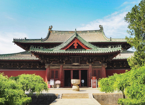
Traditional Chinese architecture, constructed mainly of wood, has a rich history and unique systematic features. There are basically two types of traditional Chinese timber structure frame systems: the through-type frame and the beam-lifted frame. The beam-lifted frame is widely used in large-scale buildings such as palaces and temples in northern China, as exemplified by . It consists of a frame layer, a DouGong layer, and a heavy roof. The through-type frame is widely used in rural housing. In this system, the columns directly support purlins, and multiple square crossbeams connect the columns along the length of the house, providing stability and support. The assembly of these structures relies on mortises and tenons, with no metal components used.
Figure 1. Traditional Chinese timber building.
Compared to traditional Western buildings with bricks and stones, wood in traditional Chinese timber structures is susceptible to degradation from aging, decay, and biological attacks. Therefore, frequent maintenance and renovation are necessary to preserve these structures. Over hundreds or thousands of years, ancient timber structures have undergone varying degrees of destruction, with residual deformation and wood degradation being the main hidden dangers to their service life (Li and Qin Citation2005; Mi et al. Citation2020; Yuan, Chen, and Guo Citation2021). The conservation of architectural heritage involves assessing the existing and potential damage to ancient timber buildings caused by natural factors. Identifying areas of weakness or damage and evaluating the effect of wood damage on the behavior of traditional Chinese timber structures are critical to ensuring the long-term preservation of these structures. However, conducting experimental studies on traditional Chinese timber structures is difficult and costly due to the complexity and scale of the wood damage, as well as the large dimensions of these structures. Therefore, numerical methods play an essential role in studying traditional Chinese timber structures.
In recent studies, several numerical models have been proposed for predicting the seismic performance of various types of traditional Chinese timber buildings. Zhang et al. (Citation2020a) and Zhang et al. (Citation2020b) have focused on timber-frame structures, Lin et al. (Citation2022) have focused on hall-style timber frames, and Wu et al. (Citation2021a), Xue, Wu, and Zhang Citation2021), and Che et al. (Citation2006) studied roof structures and the Yingxian Wooden Pagoda, respectively. These past studies have provided significant insights into understanding the behavior of timber structures. However, most of these studies have primarily focused on intact structures, with limited investigations into the behavior of damaged timber structures. Some researchers have conducted dynamic analysis to investigate the effect of performance degradation on the seismic fragility of the traditional Chinese timber structure. These studies simulated structural performance degradation by reducing wood properties, bending stiffness, and strength of joints. The results showed that performance degradation of the structure significantly reduces the probability of remaining intact by 18 % and increases the collapse probability by 10 % (Wu et al. Citation2021b). In another study, Yang et al. (Citation2021) investigated the degradation resulting from damage in the column bases and its effect on the dynamic performance of the overall timber structure by adding a cushion with different elasticity and shearing modulus at the column foot. These kinds of research have been confined to investigating the degradation behavior of traditional Chinese timber structures due to wood material performance degradation, and limited research has been done to discuss the degradation behavior due to local wood damage. Furthermore, it is worth noting that most of the previous research in this field (such as Wu et al. Citation2021b; Zhang et al. Citation2020a, Citation2020b; Lin et al. Citation2022) relied on bar-spring elements or beam elements and lacked comprehensive analysis of the strain state of individual components within traditional Chinese timber structures. To accurately assess the impact of wood damage, it is crucial to simulate the strain distribution within the structure accurately, especially for key parts of the structure.
In the following, a fundamental numerical model is presented for evaluating the degradation of the lateral performance of traditional Chinese timber structures. The model takes into account the anisotropy of wood and the embedment reaction between the components. Next, this numerical model is examined through numerical studies on a full-scale quasi-static test of the traditional Chinese timber framework (Shi et al. Citation2018). Then, degradation laws of residual deformation on the lateral performance of the structure are calculated using the numerical method and compared with experimental results for validation. Finally, by assuming different levels and distributions of wood decay at the column bases, the degradation behavior of the structures is obtained and discussed.
2. Traditional Chinese structural components of the framework
The mechanical performance of traditional Chinese timber structures is influenced by several factors, including the restoring forces of the rocking column, the embedment reaction resistance of beam-column mortise – tenon joints, and the DouGong’s damping performance (Que et al. Citation2017). According to Yingzao Fashi (Treatise on Architectural Methods or State Building Standards of pre-919, Li Citation2011; Guo Citation1998), illustrates a typical traditional Chinese timber framework from the Song Dynasty (960–1279 A.D.). This framework consists of large-diameter columns, LanEs, PuPaiFangs, SuFangs, and DouGongs, interconnected using mortises, tenons, or dowels. The columns are directly placed on the stone base without protruding pins and are fixed by the vertical load from the heavy roof. They are connected through the LanE (architrave between the columns, called LanE in Yingzao Fashi) and a PuPaiFang (a beam located on the LanEs and column tops to connect the columns and LanE, called PuPaiFang in Yingzao Fashi) resting on LanE horizontally. Dowels are inserted between the LanE and PuPaiFang to enhance the stability of the framework. A detailed connection on the column top is shown in . Dovetail – tenon joints are commonly used to connect the columns and primary beams in timber structures. DouGong (bracket set, called DouGong in Yingzao Fashi) comprises the corbels and blocks, interconnected through lap joints and dowels, and is placed on the PuPaiFang. Several SuFangs (the rail without carving, called SuFang in Yingzao Fashi) are placed on DouGongs to bear the loads from the roof and transfer them to columns through the DouGongs ().
Figure 2. Chinese timber framework.
3. Introduction of Shi et al. (Citation2018) test
A plane full-scale quasi-static loading test of a traditional Chinese timber framework conducted by Shi et al. (Citation2018) is used to illustrate the numerical model. The specimen was constructed based on the rules of the Song Dynasty (Li Citation2011) and represented a typical framework described in Chapter 2. The full-scale specimen was made of Pinus sylvestris and had a single span measuring 2.768 m × 3.895 m. shows the dimensions of the specimen and the setup for the test.
Figure 3. Dimensions of specimen and setup of test.
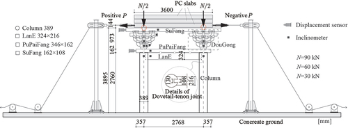
The specimen was positioned on a concrete ground without being fixed, and the weight of the roof was simulated using PC slabs. The maximum vertical load of approximately 90 kN was determined based on the dead-weight of the roof and the weight caused by natural conditions. In addition to the maximum load of 90 kN, two additional vertical loads of 30 kN and 60 kN were also applied in the test to analyze the effect of vertical load on the lateral performance of the traditional Chinese timber framework (Shi et al. Citation2018). The tests were terminated when the bearing capacity of the specimen began to decline. Most of the components did not experience significant damage during the experiment. However, embedded deformations were observed at the bottom of the PuPaiFang in contact with the edge of the column, particularly on the side of the mortise of the mortise-tenon joints, as well as within the mortise-tenon joints. Moreover, noticeable shear deformations were observed on the dowels between the LanE and PuPaiFang (Shi et al. Citation2018).
3.1. Overview of fiber beam-column model
In terms of the mechanical characteristics of traditional Chinese timber structures, the anisotropy of wood and the embedment behavior between their components pose significant challenges in predicting their behavior. In recent years, solid models and bar-spring models have been widely used to estimate the behavior of these structures. Solid models can provide detailed deformation characteristics and strain development of local regions, but they require considerable computational cost, especially for complex timber structures. On the other hand, bar-spring models or beam models are commonly used for complex timber structures because they offer a reasonable compromise between computational effort and accuracy. However, these approaches have limitations in simulating the impact of local wood damage and strain development in members.
The fiber beam-column model represents a numerical approach that bridges the gap between bar-spring models and solid models combining numerical accuracy with computational efficiency. The model divides the element into segments and discretizes its cross-section into fibers. By discretizing the cross-section into fibers and considering the nonlinear behavior of each fiber based on the material’s constitutive laws, the model can account for complex factors such as constraint effects, residual stress, and partial yielding. This is crucial for accurately predicting the behavior of traditional Chinese timber structures. Furthermore, the fiber beam-column model provides a more accurate representation of timber structures’ behavior compared to bar-spring models, without sacrificing computational efficiency. In the case of the numerical model discussed in our study (), the computation time is less than 10 seconds, indicating its high computational efficiency (computer hardware configuration: Apple Mac mini, CPU: Apple M1, RAM: 8 GB). However, it’s important to note that the fiber beam-column model may have limitations in its applicability to structures with highly irregular geometries or unique joint connections, which may not be easily modeled using this approach.
Figure 4. Fiber beam -column model.
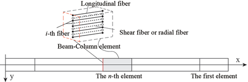
Traditional fiber beam-column models typically consider uniaxial constitutive laws of the material. However, Wang et al. (Citation2017) proposed a new plane fiber beam-column model, as illustrated in in the planar local reference system. In this model, each element is divided into several fibers, with an equal number of fibers along the element. The control points of these fibers are determined using numerical integrals of the area moment for section stiffness calculation. In this fiber beam-column model, the longitudinal stress-strain and shear stress-strain relations independently follow their respective constitutive laws. Furthermore, the model assumes that the strain distribution in the shear direction is assumed to be the same in elastoplastic behavior as in the elastic range. By working at the section level with fiber constitutive laws, the behavior under forces is expressed through the integration of fiber stresses in the longitudinal and shear direction across the cross-section.
This fiber beam-column model has also been applied to investigate the deformation characteristics of traditional Japanese timber structures, as demonstrated by Inoue and Muramoto (Citation2019). In this application, the fibers in the shear direction are utilized to represent the wood material laws in the radial direction, while the radial direction is considered to account for the anisotropy of wood and analyze the embedding characteristics between the wood components. Through this study, it has been confirmed that the strain and anisotropy of wood can be accurately captured using this fiber beam-column model, demonstrating its suitability for studying the behavior of traditional Chinese timber structures.
Subsequently, several numerical studies based on the fiber beam-column model have been conducted to examine the behavior of traditional Chinese timber structures. Hu et al. (Citation2021) developed a parallelized numerical model to simulate the stereoscopic embedding characteristics of dovetail – tenon joints. This model enables a comprehensive analysis of the complex embedment behavior that occurs when the tenon is pulled out at the joint of the beam and column. Furthermore, the behavior of the rocking column has been investigated, and a numerical model has been proposed to account for the embedment reaction between the stone base and the column foot (Hu and Muramoto Citation2022). The validity of the numerical model and its accuracy in simulating the embedment deformation in the column foot and the behavior of the rocking column have been verified. Additionally, a numerical model has been introduced to consider the embedment reaction between the rail and the column top, and its validity and accuracy have been verified by comparing the predicted behavior with experimental data (Hu and MuramotoCitation2021).
The material properties of wood exhibit significant anisotropy between the longitudinal and radial directions, and this anisotropy has a notable impact on the behavior of timber structures. Therefore, in this study, the fiber beam-column model (Wang et al. Citation2017; Inoue and Muramoto Citation2019) is utilized to consider the anisotropy of wood by assigning different material properties to the longitudinal and shear fibers. Moreover, the deformation characteristics of components in traditional Chinese timber structures, influenced by the anisotropy of wood, are taken into account in the numerical analyses. A numerical model of the timber framework () is established, as depicted in , where monotonic loading is applied to investigate the deformation characteristics of the timber framework.
Figure 5. Numerical model basing fiber beam -column model.
The PC slabs, indicated by the red circle in , are placed on the SuFangs perpendicular to the span direction, with these SuFangs slightly higher than the SuFangs parallel to the span direction. Consequently, the PC slabs are simplified to concentrate the vertical loads applied at the DouGongs.
illustrates the cross-section models of the beam-column elements, which are segmented into nine fibers. The parameters hi and Ai represent the distance from the axis and the area of the i-th fiber element, respectively; while μi denotes the shear distribution parameter of the i-th fiber element. The shear distribution is determined based on previous research (Wang et al. Citation2017; Inoue and Muramoto Citation2019).
Figure 6. Cross -section model.
3.2. Column, LanE, PuPaiFang
During the tests conducted by Shi et al. (Citation2018), it was observed that the column, LanE, and PuPaiFang components of the timber framework sustained minimal damage and primarily experienced rigid body motion. As a result, these components were segmented into two elements, as shown in . It was determined that further dividing them into multiple elements did not significantly affect the numerical results.
The constitutive model employed for these members is simplified to an ideal elastic-plastic model in both the longitudinal and shear directions of the material axis. Since the columns bear heavy vertical loads, the wood material’s constitutive law for longitudinal compression is applied to the longitudinal fibers in the column elements. For LanE and PuPaiFang elements, the bending material constitutive law is applied to the longitudinal fibers. The material constitutive law for shear in the radial direction is applied to the shear fibers. provides the material properties based on the material quality test conducted by Shi et al. (Citation2018).
Table 1. Material properties.
3.3. Rocking column
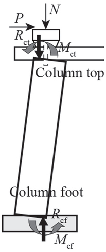
In traditional Chinese timber structures, columns are typically placed directly on stone bases without any additional connections. The lateral displacement of the overall structure is primarily governed by the rocking behavior of the columns (Yeo et al. Citation2016). depicts the behavior of timber structures under horizontal loads, where columns tend to rotate around the edge of the column foot and column top due to the vertical load exerted by the upper structure and roof. At the column top, reaction forces Rct and bending moments Mct are generated, while at the column foot, reaction forces Rcf and bending moments Mcf are present. The model of the column top elements and the column foot elements are described below.
Figure 7. Diagram of rocking column.
3.3.1. Column foot
As shown in , the rocking behavior of the column foot is mainly determined by the embedment reaction between the column foot and the stone base (Lee et al. Citation2009), and the initial deformation of the wood contact zone with the stone base significantly influences this behavior (Hu and Muramoto Citation2022).
Table 2. Constitutive model of the key component.
A fiber beam-column model has been proposed (Hu and MuramotoCitation2022) to evaluate the behavior of the column foot, incorporating the initial deformation and embedment reaction of the column foot in contact with the stone base. This model is applied with several assumptions as shown below:
In this test, the specimen was placed on a concrete ground. The behavior of the column foot connected to the concrete ground is evaluated in the same way as that connected to the stone base, considering that concrete and stone base have a similar friction coefficient (Araki et al. Citation2009).
Column slippage is disregarded in this numerical model of the framework. The static friction coefficient between the column foot and the stone base ranges from 0.7 to 0.9 (Araki et al. Citation2009), indicating that the friction force significantly exceeds the applied horizontal loads in the tests. Additionally, no slippage occurred between the column foot and the concrete ground during the tests.
The constitutive model for longitudinal fibers is shown in , while the constitutive model for shear fibers is the same as that used for column elements. The parameters for the column foot element are presented in .
Table 3. Parameters of the column foot element.
3.3.2. Column top
The rotational constraint of the column top mainly arises from the embedment reaction between the column top and PuPaiFang (Takino et al. Citation2020; Hu et al. Citation2021). In traditional Chinese timber buildings, significant residual deformation is commonly observed at the PuPaiFang directly connected to the column due to the smaller wood compression modulus in the radial direction compared to the longitudinal direction (Li and Qin Citation2005). As shown in , embedment deformation predominantly occurs on the PuPaiFang.
To capture the embedment reaction at the column top, a fiber beam-column model has been proposed in the literature by Hu and Muramoto (Citation2021). This model is applied to analyze the behavior of the column top incorporating the following assumptions:
The constraint provided by the dowel inserted between the PuPaiFang and column top is disregarded in the numerical model. This decision is based on the fact that the dowel’s cross-sectional area accounts for only 1.55 % of the column, and previous studies have indicated that the dowel has a negligible influence on the behavior of the rocking column (Kawai Citation2018).
Column top elements are positioned between the column and PuPaiFang to simulate the relative rotation between the two components. The length of the column top element corresponds to the distance between the PuPaiFang and LanE in the framework model.
The cross-sectional area of the column top elements represents the region of the column excluding the dovetail mortise. As shown in , dovetail – tenon joints connect the LanE to the columns at the top of the column. However, due to inconsistencies between the dovetail – tenon joints and rocking column deformation, as well as gaps between the PuPaiFang and the tenon resulting from installation deviations, no embedment deformation was observed on the part of the PuPaiFang in contact with the tenon during the tests (Shi et al. Citation2018). Thus, the embedment reaction on the top of the tenon is disregarded.
Considering the embedment behavior of the column top, the actual contact area between the column and the PuPaiFang is considered the cross-section area as the column top element (Hu and Muramoto Citation2021). Combining this with assumption 3, the cross-section area model of the column top element is depicted in . Considering the anisotropy of wood, the material properties of wood in the radial direction are applied to the longitudinal fibers to represent the embedment behavior between the column top and PuPaiFang. The constitutive model for these fibers is shown in . The shear behavior is evaluated in the same way as for the column elements. The parameters of the column top element are presented in .
Table 4. Parameters of column top element.
3.4. Dovetail – tenon joint
The diagram of the dovetail – tenon joint is presented in , illustrating its mechanical performance, which comprises friction resistance resulting from compression on the side of the tenon and embedment reaction on the top and bottom of the tenon (Hu et al. Citation2021).
In this study, a spring element is used to model the behavior of the rotation of dovetail – tenon joints. The restoring force characteristics of the spring element are determined using the parallelized fiber beam-column model (Hu et al. Citation2021). The stiffness value of the spring element is derived from the numerical analysis results. The parallelized fiber beam-column model accounts for the anisotropic properties of wood by incorporating 17 fibers in the dovetail-tenon element. This model enables the evaluation of the complex embedment behavior that arises when the tenon is pulled out at the joint between the beam and column, including embedment derived from the top and bottom surfaces of the tenon, as well as friction resulting from embedment on the side of the tenon. The accuracy of the parallelized fiber beam-column model has been verified through simulations of several tests conducted on dovetail-tenon joints (Hu et al. Citation2021). However, in this fiber beam-column model, all components should be equipped with the same number of fibers. Considering the significant computation cost associated with using 17 fibers for this complex framework model, a spring element is used as an alternative to effectively simulate the behavior of dovetail – tenon joints in numerical analysis.
The basic dovetail – tenon joint that has been discussed by (Hu et al. Citation2021) is presented in , and its corresponding numerical model based on the parallelized fiber numerical model is shown in . However, in the framework (; ), where the PuPaiFang is positioned on top of the LanE component, there are differences in the boundary constraints of the dovetail-tenon joint compared to the basic dovetail-tenon joint discussed by Hu et al. (Citation2021). These differences can affect the behavior of the dovetail-tenon joint. To account for these differences in the numerical analysis, the restoring force characteristics are calculated following the assumptions below.
Figure 8. Dimensions of dovetail – tenon joint.
Figure 9. Numerical model of Figure.
The elastic coefficient of the friction derived from the compression on the side of the tenon KcvF is assumed to be four times higher than the value determined by Hu et al. (Citation2021). This is because, in the framework, as shown in , the PuPaiFang rests on the LanE, providing a boundary constraint that restricts the rotational deformation of the tenons and contributes to preventing tenon pull-out. Experimental studies have shown that the presence of PuPaiFang increases the stiffness and ultimate bearing capacity of the dovetail – tenon joints approximately four times (Xie et al. Citation2015).
As mentioned in Subsection 3.3.2, the embedment reaction on the top of the tenon is disregarded when estimating the behavior of the dovetail – tenon joints. Additionally, the gap between the tenon and the LanE was assumed to be 1 mm due to limited information.
The friction coefficient applied to wood is 0.40, based on friction material tests (Shi Citation2018). presents the material properties and parameters of the dovetail – tenon joints. For a more detailed explanation of this parallelized fiber numerical model, please refer to Hu et al. (Citation2021). The moment – rotation deformation relationship of the dovetail – tenon joints obtained from numerical analysis is used in the restoring force model of the dovetail – tenon joint elements ().
Table 5. Material properties and parameters of dovetail – tenon element.
3.5. DouGong
In traditional Chinese timber structures, the rotation of the structure primarily depends on the column frame layer, while the DouGongs are primarily involved in translational motion (Meng, Li, and Yang Citation2018). Almost all components of the DouGong remain elastic during the test (Shi et al. Citation2018). The restoring force of the DouGong is influenced by the embedment behavior among its components. However, due to the complex connection of its components (; ), fully considering the characteristics of the DouGong in the analysis of overall structures is challenging. Thus, a spring element is proposed to estimate the rotation of DouGong joints in this study.
A bilinear restoring force model for estimating the behavior of DouGong provided by Sui, Zhao, and Xue (Citation2010), is applied in this study and presented in . K01 and K02 are the elastic stiffness and plastic stiffness of the DouGong’s restoring force model, respectively. The spring element is constructed based on the following assumptions:
As shown in the DouGong diagram (), since the behavior of connecting with SuFang at the top and the PuPaiFang at the bottom of the DouGong is considered in this restoring force model, these connection’s behaviors are not calculated separately in the numerical model.
The parameters of this restoring force model were obtained through experimental studies (Sui, Zhao, and Xue Citation2010). To account for the differences in dimensions and vertical loads of the DouGong, the parameters of the restoring force model in this study are adjusted based on previous research (Tsuwa et al. Citation2004; Kim et al. Citation2004). The stiffness of the DouGong is proportional to the vertical load and the cubic dimension (Tsuwa et al. Citation2004; Kim et al. Citation2004). Hence, the elastic stiffness K1 and plastic stiffness K2 of the DouGong’s restoring force model can be adjusted as
(1)
N0 represents the vertical load of the previous test study (Sui, Zhao, and Xue Citation2010). The dimensions of the DouGongs are evaluated using the diameter of the columns that correspond to the DouGongs. D0 represents the diameter of the column in the previous test study (Sui, Zhao, and Xue Citation2010), while D1 represents the diameter of the column in the test discussed in this study (Shi et al. Citation2018). Based on these considerations, the parameters of the DouGong element are presented in .
Table 6. Parameters of DouGong element.
3.6. Dowel
As shown in , three dowels were inserted between the LanE and PuPaiFang components. These dowels are simplified into a single element (). The cross-sectional area of this element is the sum of the cross-sectional areas of the individual dowels; The constitutive model for the longitudinal fibers is the same as that used for the LanE and PuPaiFang components, while the shear fibers are assumed to have compression material properties in the radial direction of the wood ().
3.7. SuFang
Five SuFangs are arranged parallel to each other and intersect with the top of the DouGong through lap joints (). These SuFangs are simplified as a single SuFang member in the numerical frame model (). Similar to the division of the LanE and PuPaiFang, the SuFang member is divided into two elements along the axial direction. The area of each SuFang element is the sum of the cross-sectional areas of the individual SuFang. The constitutive models applied to the fibers in the SuFang elements are the same as those used for the LanE.
4. Analysis results and discussion
This chapter presents a comparison between the results of the tests and the numerical analyses to investigate the accuracy of the numerical model from Chapter 4. The experimental tests were conducted under three different vertical load grades (Shi et al. Citation2018). To assess the validity of the numerical model in simulating the effects of vertical loads on the behavior of traditional Chinese timber frame, the numerical simulations were compared with the results obtained from these tests under the three different vertical load conditions. The comparison analysis includes evaluating the degradation behavior of stiffness and bearing capacity in timber structures due to residual deformation and local wood damage. Lateral force – horizontal displacement (as well as lateral force-rotation angle, calculated by dividing the displacement by the height of the column) relationships are obtained by gradually applying increasing lateral loads. The same numerical model was used for analyses in different loading directions.
Due to the simplification of DouGongs and dovetail – tenon joints as spring elements, the strain development of these components is not discussed in the study. The resisting moment of the overall traditional Chinese timber framework is primarily determined by the rocking column and dovetail – tenon joints, with the rocking column providing the majority of the restoring force (Meng, Li, and Yang Citation2018). Thus, this study primarily focuses on the impact of column damage on the mechanical performance of the overall timber structure.
4.1. Analysis results in the case of 30 kN
presents a comparison between the envelope curves of cyclic loading tests and the numerical results for a vertical load of 30 kN. The dotted lines represent the test results, while the solid lines represent the numerical results. The comparison shows good agreement between the two. Furthermore, the strain development state was investigated, and it was observed that all elements remained in the elastic range until the end of the test at 0.044 rad. The right column was taken as an example to illustrate the stress distribution in the column foot and top element. displays the stress states in both loading directions. “x” represents the location of fibers in the beam-column element, and the color shade represents the state of maximum compression stress. From the figure, it can be observed that the column foot experienced only slight compression, while the edge of the column top approached yielding.
Figure 10. Comparison between analysis and test results.
Figure 11. Stress distribution on column foot and column top.
4.2. Analysis results of other cases
The tests included three vertical load cases ranging from 30 kN to 90 kN on the same frame specimen. Residual deformation, which can weaken the bearing capacity and stiffness of timber structures (Chen et al. Citation2018), was considered in the analysis of the 60 kN and 90 kN cases. The yield states of the column top elements before each vertical load case analysis are illustrated in the upper part of .
Since all elements remained elastic during the 30 kN test case, in the 60 kN test case, the relationship between lateral force – horizontal displacement was obtained using the same numerical model as the 30 kN case ( (b)). The numerical result is broadly consistent with the test result. Furthermore, the maximum compression stress states of the fibers were investigated ( (b)). Due to the lower stiffness and strength of wood in the radial direction compared to the longitudinal direction, the column tops yield at both ends, with the yield zone accounting for 9.9 % of the total column top cross-section area. The column foot still experiences slight stress, while other elements remain elastic.
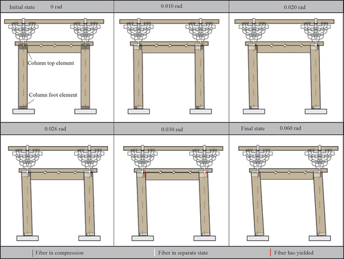
illustrates the change in the stress state of the column foot and column top with the rotation of the framework. Here, the behavior under positive loading was taken as an example. It shows how the stress distribution evolves as the framework rotates throughout the entire loading process. The rotation of the column frame layer is found to dominate the deformation of the overall framework, which is consistent with the deformation characteristic of the test. When the framework deforms beyond 0.01 rad, more than half of the column top and foot separate from the PuPaiFang or stone base, and the separation area increases as the framework rotates. In , the “o” symbols represent the moments when the fibers yield. Under positive loading, the plastic deformation of the framework begins at 0.026 rad. The first “o” symbol in represents the yielding of the edge fiber on the mortise side of the left column’s column top element, while the second “o” symbol represents the yielding of the first edge fiber on the side without mortise in the right column at 0.03 rad. Under negative loading, the fiber yield sequence is reversed, with the edge fiber on the mortise side of the right column yielding first. No other fibers yield until the end of the test at 0.060 rad.
Figure 12. Behavior of rocking column with the rotation of framework.
To account for the residual deformation observed in the 60 kN test case when analyzing the framework’s behavior under a 90 kN vertical load, the behavior of yielded fibers in the column-top element is estimated using the plastic part of the column-top element’s constitutive model (). The other elements are modeled the same as in the 30 kN case. The comparison between the numerical and test results is shown in , and the stress distribution is shown in .
The numerical results closely match with the test results until the horizontal displacement reaches 80 mm. However, they start to diverge afterward. In the numerical analysis, the bearing capacity tends to decrease, while in the test, it continues to increase. This discrepancy may be attributed to the underestimation of the constraint provided by the dowels between the LanE and PuPaiFang. The experimental observations of this test (Shi et al. Citation2018) indicate that the dowels inserted between the LanE and PuPaiFang considerably slow down the rate of tenon pull-out when the horizontal displacement exceeds 80 mm. The dowels provide constraint through embedment and friction among the dowels, LanE, and PuPaiFang. Currently, accurately considering these effects in the fiber beam-column model is challenging. Further research is expected to enhance our understanding of this behavior.
The three numerical analyses conducted in this study show close predictions of the initial stiffness and maximum bearing capacity of the framework under different vertical loads. The difference in the maximum bearing capacity between the numerical and test results is within 7.9 %, indicating acceptable numerical accuracy.
Referring to the strain state (), it is observed that most of the elements remain within the elastic range even with vertical loads up to 90 kN. Plastic deformation is concentrated in the column top element. In the 60 kN case, the first edge fiber on the mortise side has already yielded, and in the 90 kN case, the second edge fiber on the mortise side starts to yield when the rotation deformation of columns exceeds 0.037 rad, represented by the “o” symbol in . The yield zone extends to 17.6 % of the total cross-sectional area of the column top element. Based on the experimental observations mentioned in Chapter 3, some embedding deformation occurs at the bottom of PuPaiFang where it contacts the edge of the column, particularly on the mortise side of the dovetail – tenon joint. The DouGong, columns, and beams remain within the elastic range during the tests (Shi et al. Citation2018). These strain characteristics are accurately captured by the numerical analyses, demonstrating the accuracy of the fiber beam-column model in simulating the strain development of the framework.
4.3. Effect of residual deformation
In addition to the three tests mentioned earlier, Shi X. (Citation2018) conducted three additional tests to investigate the degradation laws of stiffness and bearing capacity in the traditional Chinese timber structures caused by accumulated residual deformation. These additional tests were carried out in the sequence of 90 kN (Test 4)→60 (Test 5) kN→30 kN (Test 6), referred to as PST2. The three tests mentioned earlier in the sequence of 30 kN (Test 1)→60 kN (Test 2)→90 kN (Test 3), referred to as PST1.
Similar to the analysis conducted in Section 4.2, the impact of accumulated residual deformation on the behavior of the framework was estimated through the monotonic loading analyses, based on the development of the yield area of components. The left side of shows the comparison of the lateral force-horizontal displacement relationship between the numerical analyses and the tests. Except for the column-top elements, the other elements remained elastic, and the yield area of the column-top element did not expand after Test 3. The right side of depicts the cross-section models of the column top element, illustrating the yield state prior to each analysis case. Due to the asymmetry of experimental curves in different loading directions, the average value of the results in both directions was used to reflect the degradation behavior of the framework. Based on the test results, the accumulated residual deformation weakened the framework in terms of both stiffness and bearing capacity in the 30 kN case. While the initial stiffness was hardly affected by residual deformation, the bearing capacity of the framework in PST2 showed a reduction compared to PST1 when the displacement exceeded 25 mm in other cases. These degradation characteristics are well captured by the numerical analyses, especially in the 60 kN and 90 kN cases. presents the reduction in bearing capacity between the two tests under the same vertical load, as well as the effective load-bearing area of the column top element. The reduction values were averaged from 25 mm to the maximum displacement to evaluate the degradation of bearing capacity, considering the imbalance in the reduction of bearing capacity. Although the bearing capacity of the framework in PST2 starts to decline at a relatively small displacement of 30 kN, the reduction values were still calculated from 25 mm to the maximum displacement to maintain consistency with the other analysis cases. Despite the same difference in the effective load-bearing area in the 30 kN and 60 kN cases, a more severe reduction in bearing capacity was observed in the 30 kN case, suggesting that the vertical load may mitigate the impact of residual deformation. The numerical model underestimates the reduction in the 30 kN case, which could be attributed to the impact of dovetail – tenon joint looseness under cyclic loading. The average reduction of bearing capacity between the tests and numerical analysis ranges from 0 % to 13.2 %. Although the numerical analysis did not consider the accumulated damage from cyclic loading, the degradation laws of the framework in terms of stiffness and bearing capacity were approximately captured, demonstrating acceptable accuracy in predicting potential damages in traditional Chinese timber structures and simulating strain development in the model. Furthermore, considering the changes in the stress state with the rotation of the framework (as shown in in Section 4.2), the bearing capacity of traditional Chinese timber structures might be reduced after experiencing large deformations exceeding 0.026 rad.
Figure 13. Comparison between analysis and test results.
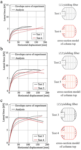
Table 7. Reduction of average bearing capacity.
4.4. Degradation behavior of column foot
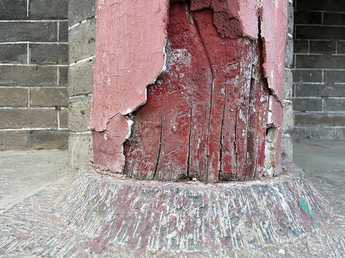
In traditional timber buildings, wood cracks are common but do not negatively affect structural safety, while wood decay poses a great risk (Yuan, Chen, and Guo Citation2021). The column foot, which floats on the stone base, is particularly susceptible to rain erosion and decay, especially at the edge of the column base (Zhou Citation2015; Qin et al. Citation2022). The effective load-bearing area at the bottom of some columns can be less than 50 % of the cross-sectional area (Qin et al. Citation2018). provides an example of decay at the column base. The column foot plays a vital role in resisting horizontal loads or earthquakes but is also a common site for wood decay. Therefore, the degradation behavior of traditional Chinese timber structures caused by wood decay in the column bases was chosen as an example for discussion in this section.
Figure 14. Decay in the edge of column foot.
To understand the impact of wood decay on the behavior of traditional Chinese timber structures, three damaged cross-section models of the column foot element were considered and illustrated in . These models represent different levels and distributions of wood decay at the column bases. In damage model 1, decay occurs at both ends of the column foot, resulting in an effective load-bearing area that accounts for 87.8 % of the total cross-sectional area of the column foot. In model 2, the damage zone is expanded, leading to a decrease in the effective load-bearing area, which now amounts to 66.9 % of the total cross-sectional area. Model 3 focuses the damage in the middle of the column foot, with the same damaged area as model 2. The stiffness of fibers in the damage zone is assumed to be 0.
Figure 15. Damage model of column foot.
The three damaged cross-section models of the column foot elements, along with a numerical model without damage, were subjected to analysis under three vertical load cases. The results are presented in . Notably, damage model 2 exhibited a marked degradation in maximum bearing capacity and initial stiffness, while model 3 appeared unaffected and even demonstrated a slight increase in stiffness under a vertical load of 90 kN. The behavior observed in model 3 can be attributed to the increased compression stress on the column foot caused by the reduction in load-bearing area. This increased stress slows down the lifting speed of the column foot without affecting the embedment behavior at the edge of the column foot, thus compensating for the impact of the damage. presents the reductions in maximum bearing capacity and stiffness for these models. The stiffness values were calculated within the displacement range of 0 to 25 mm. Damages at the edge of the column foot lead to a reduction in framework stiffness and bearing capacity ranging from 8.5 % to 27.5 %, with the degree of degradation becoming more severe as the vertical load increases. This highlights the significant role played by the edge of the column foot in resisting lateral loads. Even in the case of damage model 1, which retains an effective bearing area of 87.8 %, there is still a reduction of 8.5 % to 18.6 % in both stiffness and maximum bearing capacity.
Figure 16. Comparison between analysis and test results.
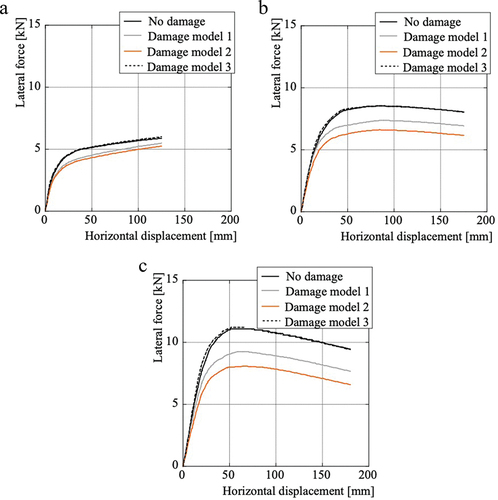
Table 8. Reduction of maximum bearing capacity and initial stiffness.
According to the Standard for Maintenance and Strengthening of Ancient Timber Buildings (Ministry of Housing and Urban-Rural Development of the People's Republic of China Citation1992), column foot maintenance is generally considered unnecessary as long as the effective load-bearing area exceeds 60 % of the cross-sectional area, without considering the impact of wood damage distribution. However, the analysis results show that when wood damages are concentrated on the edge of the column base, the stiffness and maximum bearing capacity of the timber frame can be reduced by 12.4 % to 27.5 %, even if the effective load-bearing area is 66.9 %. In contrast, when wood damages occur in the middle of the column base, the safety of structures can still be maintained. Therefore, it is necessary to consider the distribution of wood damage in the column base to accurately estimate the degradation behavior of traditional Chinese timber structures. Additionally, special attention should be given to wood damages occurring at the edge of the column base, as they have a significant impact on the overall structural performance.
5. Conclusion
This study provides a comprehensive investigation of the degradation behavior of traditional Chinese timber structures, which can serve as a valuable reference for assessing and preserving traditional Chinese timber buildings. The proposed fiber beam-column model, considering wood anisotropy and the embedment behavior between components, accurately predicts residual deformation and degradation in lateral performance caused by wood damage. The conclusions of the study are as follows:
The fiber beam-column model demonstrates good computational accuracy when compared with corresponding experimental results of traditional Chinese timber frameworks.
The proposed fiber beam-column model effectively predicts the degradation laws of residual deformation, providing a reliable evaluation of stiffness and bearing capacity degradation due to residual deformation.
Damage to the edge of the column base significantly degrades the bearing capacity and stiffness of traditional Chinese timber structures. The degradation is more severe under heavier vertical loads.
The distribution of wood damage in the column base has a notable impact on the behavior of traditional Chinese timber structures. Damage to the edge of the column base requires more attention when monitoring the health of these structures.
This study establishes a fundamental numerical model for assessing the impact of wood damage and residual deformation on the lateral performance of traditional Chinese timber structures by incorporating data on the properties of damaged wood into the model. The findings from this study contribute to discussions and further research on evaluating the degradation of lateral performance of traditional Chinese timber structures.
Acknowledgements
Permission to quote from protected by copyright has been granted by Mr. Lu ma-ke.
Disclosure statement
No potential conflict of interest was reported by the author(s).
Additional information
Funding
Notes on contributors
Rong Hu
Dr. Rong Hu is a Ph.D in the school of Civil Engineering, Qingdao University of Technology, China. Her major field of study is traditional Chinese timber structures.
Makoto Muramoto
Dr. makoto Muramoto is an associate professor in the graduate school of design and architecture, Kyoto Institute of Technology, Japan. His research interests include: Numerical Analysis; Architectural robotics; Timber structures; Mud wall; Structural mechanics.
Jun Li
Dr. Jun Li is a professor in the school of Civil Engineering, Qingdao University of Technology, China. Her major research fields include seismic-resistance performance of steel structures and timber structures.
References
- Araki, Y., D. Lee, T. Endo, N. Yoshida, and K. Uetani. 2009. “Static Friction Coefficient Between Column Base and Foundation Stone of Japanese Traditional Timber Buildings.” AIJ Journal of Technology and Design 15 (30): 405–409. (in Japanese) https://doi.org/10.3130/aijt.15.405.
- Che, A., Y. He, X. Ge, T. Iwatate, and Y. Oda. 2006. “Study on the Dynamic Structural Characteristics of a Traditional Timber-Yingxian Wooden Pagoda.” Soil and Rock Behavior and Modeling 194 (11): 390–398. https://doi.org/10.1061/40862(194)52.
- Chen, J., T. Li, Q. Yang, X. Shi, and Y. Zhao. 2018. “Degradation Laws of Hysteretic Behavior for Historical Timber Buildings Based on Pseudo-Static Tests.” Engineering Structures 156:480–489. https://doi.org/10.1016/j.engstruct.2017.11.054.
- Guo, Q. 1998. “Yingzao Fashi: Twelfth-Century Chinese Building Manual.” Architectural History 41:1–13. https://doi.org/10.2307/1568644.
- Hu, R., and M. Muramoto. (2021). “Analysis of Column Rocking Behavior Considering Stress Distribution of Column Using Fiber Elements.” Proc. Architectural Institute of Japan Kinki Chapter Architectural Research Meeting, Osaka, Japan 61: 217–220. (in Japanese)
- Hu, R., and M. Muramoto. 2022. “Analysis of Column Rocking Column Behavior Considering Stress Distribution of Column Using Fiber Elements.” Journal of Structural and Construction Engineering, AIJ 87 (802): 1201–1212. (in Japanese) https://doi.org/10.3130/aijs.87.1201.
- Hu, R., M. Muramoto, S. Inoue, and J. Li. 2021. “Parallelized Fiber Model of Beam-Column Finite Element Method Considering Hysteresis Characteristics of Joints-Numerical Analysis of Dovetail Tenon Joints.” Journal of Structural Engineering 67B: 403–412. (in Japanese)
- Inoue, S., and M. Muramoto. 2019. “A Proposal for Beam-Column FEM Model of Wooden Framework.” Journal of Structural Engineering 65B: 247–255. (in Japanese)
- Kawai, N. 2018. “Static Loading Test on Column Rocking Resistance Using Scale Models, Part 2. Influence of Column Section Shape and Theoretical Solution Considering Initial Deformation.” Summaries of Technical Papers of Annual Meeting (Architectural Institute of Japan), Structure III, Tohoku, Japan, 183–184. (in Japanese)
- Kim, H., K. Fujita, I. Tsuwa, F. Uehiro, I. Saito, M. Koshihara, and I. Sakamoto. (2004). “Dynamic Loading Test of Kumimono Used in Traditional Wooden Architecture Part2 Load-Displacement Relationships and Characteristic of Deformation.” Summaries of Technical Papers of Annual Meeting (Architectural Institute of Japan), C-1, Structure III, Hokkaido, Japan, 25–26. (in Japanese)
- Lee, D., Y. Araki, T. Endo, N. Yoshida, and K. Uetani. 2009. “Modeling of Column Base for Traditional Timber Buildings Based on Local Compression Experiments at Contact Surface Between Column Base and Foundation Stone.” Journal of Structural and Construction Engineering, AIJ 74 (639): 865–872. (in Japanese) https://doi.org/10.3130/aijs.74.865.
- Li, J. 2011. Yingzao Fashi. Beijing: People’s Publishing House (in Chinese).
- Lin, Y., Q. Chun, C. Zhang, Y. Han, and H. Fu. 2022. “Research on Seismic Performance of Traditional Chinese Hall-Style Timber Buildings in the Song and Yuan Dynasties (960–1368 AD): A Case Study of the Main Hall of Baoguo Temple.” Journal of Wood Science 68 (1): 2–25. https://doi.org/10.1186/s10086-021-02009-y.
- Li, T., and H. Qin. 2005. “Structural Analysis and Repair of Yingxian Wooden Tower.” Engineering Mechanics 22 (Sup): 199–212. (in Chinese)
- Meng, X., T. Li, and Q. Yang. 2018. “Lateral Structural Performance of Column Frame Layer and Dou-Gong Layer in a Timber Structure.” KSCE Journal of Civil Engineering 23 (2): 666–677. https://doi.org/10.1007/s12205-018-0259-4.
- Mi, X., X. Meng, Q. Yang, T. Li, and J. Wang. 2020. “Analysis of the Residual Deformation of Yingxian Wood Pagoda.” Advances in Civil Engineering 2020:1–12. https://doi.org/10.1155/2020/2341375.
- Ministry of Housing and Urban-Rural Development of the People's Republic of China. 1992. Technical Code for Maintenance and Strengthening of Ancient Timber Buildings.” GB/50165–92. (in Chinese)
- Qin, S., N. Yang, H. Hu., and L. Zhang. 2018. “Study on Dynamic Characteristics of a Damaged Ancient Timber Structure of Ming-Qing Dynasty.” Journal of Building Structures 39 (10): 130–137. (in Chinese) https://doi.org/10.14006/j.jzjgxb.2018.10.015.
- Qin, Q., N. Yang, Z. Zao, and J. Dong. 2022. “Damage Analysis and Protection of Timber Structure of Tongdao Hall in the Imperial Palace.” Journal of Civil and Environmental Engineering 44 (2): 119–128. http://doi.org/10.11835/j.issn.2096-6717.2021.056. (in Chinese)
- Que, Z., Z. Li, X. Zhang, Z. Yuan, and B. Pan. 2017. “Traditional Wooden Buildings in China.” Wood in Civil Engineering Intech https://doi.org/10.5772/66145.
- Shi, X. 2018. “Experimental Study and Theoretical Analysis for Hysteretic Behaviors of Full-Scale and Single-Span Traditional Timber Structure.” Taiyuan University of Technology. (in Chinese)
- Shi, X., T. Li, Y. Chen, J. Chen, and Q. Yang. 2018. “Full-Scale Tests on the Horizontal Hysteretic Behavior of a Single-Span Timber Frame.” International Journal of Architectural Heritage 14 (3): 398–414. https://doi.org/10.1080/15583058.2018.1547799.
- Sui, Y., H. Zhao, and J. Xue. 2010. “Experimental Study on Lateral Stiffness of DouGong Layer in Chinese Historic Buildings.” Engineering Mechanics 27 (3): 74–78. (in Chinese).
- Takino, A., K. Mukaibo, Y. Araki, Y. Miyamoto, H. Isoda, and N. Kawai. 2020. “Experimental Study on Restoring Force Characteristics of Column Rocking with Horizontal Cross Members and Varying Axial Force.” Journal of Structural and Construction Engineering, AIJ 771:715–723. (in Japanese) https://doi.org/10.3130/aijs.85.715.
- Tsuwa, I., K. Fujita, H. Kim, F. Uehiro, I. Saito, M. Koshihara, and I. Sakamoto. (2004). “Dynamic Loading Test of Kumimono Used in Traditional Wooden Architecture Part1 Micro Tremor Measurement and Free Vibration Test.” Summaries of Technical Papers of Annual Meeting (Architectural Institute of Japan), C-1 Structural III, Hokkaido, Japan, 23–24. (in Japanese)
- Wang, D., Y. Hayashi, M. Muramoto, and K. Morisako. 2017. “Elastic-Plastic Beam-Column FEM Model with Fiber Elements Evaluating Shear Deformation.” Journal of Structural and Construction Engineering, AIJ 82 (737): 1035–1045. (in Japanese) https://doi.org/10.3130/aijs.82.1035.
- Wu, C., J. Xue, D. Song, and Y. Zhang. 2021a. “Seismic Performance Evaluation of a Roof Structure of a Historic Chinese Timber Frame Building.” International Journal of Architectural Heritage 16 (10): 1474–1495. https://doi.org/10.1080/15583058.2021.1894503.
- Wu, C., X. Zhang, J. Xue, H. Ma, and J. Wu. 2021b. “Effect of Performance Degradation and Infilled Walls on Seismic Fragility Assessment of Traditional Chinese Timber-Frame Structure.” International Journal of Architectural Heritage 16 (8): 1252–1269. https://doi.org/10.1080/15583058.2021.1879311.
- Xie, Q., B. Du, W. Xiang, P. Zheng, and Y. Cui. 2015. “Experimental Study on Seismic Behavior and Size Effect of Dovetail Mortise-Tenon Joints of Ancient Timber Buildings.” Journal of Building Structures 36 (3): 112–120. (in Chinese) https://doi.org/10.14006/j.jzjgxb.2015.03.014.
- Xue, J., C. Wu, and Y. Zhang. 2021. “Analysis of Dynamic Characteristics and Seismic Response of a Historic Roof Structure Of. Palace-Style Timber Frame Structure.” Journal of Building Structures 42 (10): 87–95. (in Chinese).
- Yang, S., J. Wang, Y. Wang, and T. Li. 2021. “Dynamic Analysis of Seventh-Class Column Frame with Cushion.” IOP Conference Series Earth and Environment Science 634 (1): 012125. https://doi.org/10.1088/1755-1315/634/1/012125.
- Yeo, S., K. Komatsu, M. Hsu, and Z. Que. 2016. “Mechanical Model for Complex Brackets System of the Taiwanese Traditional Dieh-Dou Timber Structures.” Advances in Structural Engineering 19 (1): 65–85. https://doi.org/10.1177/1369433215618269.
- Yuan, X., Y. Chen, and W. Guo. 2021. “Features and Prevention of Common Damages in Ancient Timber Structures.” Chinese Journal of Wood Science and Technology 35 (5): 54–59. (in Chinese) https://doi.org/10.12326/j.2096-9694.2020165.
- Zhang, X., Y. Han, C. Wu, C. Hu, and F. Bai. 2020a. “Discrete Element Simulation and Collapse Vulnerability Analysis of Chinese Ancient Timber-Frame Structure.” Journal of Vibration Engineering 33 (6): 1150–1161. (in Chinese) https://doi.org/10.16385/j.cnkii.sn.10044523.2020.06.006.
- Zhang, X., C. Wu, J. Xue, and H. Ma. 2020b. “Fast Nonlinear Analysis of Traditional Chinese Timber-Frame Building with Dou-Gon Fast Nonlinear Analysis of Traditional Chinese Timber-Frame Building with Dou-Gon.” International Journal of Architectural Heritage 14 (8): 1252–1268. https://doi.org/10.1080/15583058.2019.1604847.
- Zhou, Q. 2015. “Typical Structure Problems of Wooden Columns in the Ancient Buildings of the Forbidden City.” Journal of Water Resources and Architectural Engineering 13 (6): 109–112. (in Chinese). https://doi.org/10.3969/j.issn.1672-1144.2015.06.020.