
 ?Mathematical formulae have been encoded as MathML and are displayed in this HTML version using MathJax in order to improve their display. Uncheck the box to turn MathJax off. This feature requires Javascript. Click on a formula to zoom.
ABSTRACT
Structural health monitoring aided with the electromechanical impedance technique (EMI) is gaining popularity among researchers due to its dual sensing application and noise-free sensor results, and it is very sensitive to inceptive structural alternation. A thin coat of adhesive permanently bonds the piezoelectric transducers to the host structure. The bonding layers effect the mechanical interaction between the structure and the piezoelectric material as they act as a pure shear connector. Furthermore, the presence of shear alters the actuation and sensing capability of the PZT (Piezoelectric Transducer) patch, hence the efficiency of EMI technique. In this paper, a novel alloy (Sn-Ag) based bond is introduced for sensor integration and studied for bond behaviour in order to improve the bond’s quality in the EMI approach for structural health monitoring. The first part of experiment deals bond geometry degradation deals with the effect of disbond towards impedance-based coupled signature. The last part of experiment focuses on bond exposure to environmental degradation and it’s durability. From the experimental results, it is found that the Sn-Ag alloy-based bond formed between the structure and the piezoelectric transducer with the help of thermos-activated process is extremely strong and establishes a unique bond layer connection to the structure, which has a more resistive capacity towards moisture, chemical, and also temperature, compared with the epoxy-based bond.
1. Introduction
Structural Health Monitoring (SHM) and Non-destructive technique (NDT) are widely used techniques in aeronautical, civil, and mechanical engineering to increase serviceability and life span of structure. SHM has the capability of providing continuous structural integrity monitoring. Owing to the upgraded implementation of a robust SHM system in civil/mechanical fields, structural maintenance costs would be reduced while dependability and safety will be boosted (Qing et al. Citation2006). Most monitoring systems are predicated on the notion that damage will change the structural mass, stiffness, damping, or energy dissipation qualities, hence modifying the structure’s dynamic response (Sohn et al., Citation2002). In regular deterioration of the structure, the incipient change in structural behaviour is not very sensitive to frequency-based damage indices. Furthermore, the nonmodal-based impedance technique does not depend on modal parameters and is sensitive towards very minute structural change. The electromechanical impedance (EMI) technique uses impedance spectroscopy to identify damage with sensitivity equivalent to localized ultrasonic approaches (Soh, Yang, and Bhalla Citation2012). The EMI technique is based on the EM coupling properties of piezoelectric transducer (PZT) materials; when activated electrically, the PZT patch, whether surface-bonded or embedded in it, creates a localized strain parallel to the structure (Annamdas Citation2007). The PVDF and PZT patches are easily accessible and commercially available piezoelectric materials that have undergone significant improvement for employment in SHM (Gandhi and Thompson Citation1992). The employment of PZT patch is an important part of a distributed active SHM process because of its lightweight, inexpensive and energy efficient and most importantly as self-sensing mechanism, which acts as actuators and sensors on their own (Han, Wang, and Sun Citation2008, Civera and Surace Citation2022; Qing et al. Citation2006). The sensitivity of the specimen to this excitation can be measured as an electric current (and hence the admittance), which is a function of structural impedance (Annamdas and Rizzo Citation2009; Zagrai and Giurgiutiu Citation2001). The shape control mechanism of PZT patch is very much effective for vibration control i.e. active and passive control for structural damper (Wang et al. Citation2019, Citation2020, Citation2020, Citation2021, Citation2022, Citation2023, Citation2023; Wang, Zhou, and Shi Citation2023a; Citation2023b, Zhang et al., Citation2023; Zhang, Wang, and Shi Citation2023)
For the EMI technique, the modulated piezoelectrical current is measured due to piezo-coupled interaction between the PZT patch and the structure, which are measured in terms of electrical admittance (conductance and susceptance). The coupled admittance signature (inverse of impedance), the actuator’s material properties, structural configuration, and boundary conditions, and any damage to the host structure will cause these characteristics to alter. Liang et al.3 derived the expression for the EMI signature for a one-dimensional SDOF system (refer )
Figure 1. Liang’s 1D impedance model (Moharana, Citation2012).
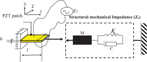
where is the piezo-coupled admittance, ω the angular frequency, w, l, hp are the geometrical properties of the PZT patch, and
are the complex piezoelectric permittivity and Young’s modulus. Za and Zs are the mechanical impedance of the PZT patch and host structure, respectively. k denotes the wave number. For adequate signal transfer, a proper connection between the transducer and the structure becomes essential. In past studies, it has been suggested that a strong connection between the transducer and the framework is necessary for the fixed in situ implantation of the PZT patch. The piezo-deformed strain caused due to interaction is transferred from the structure to the sensor using this contact. A patch and a structure should ideally be perfectly bonded, with the patch’s stiffness being greater than the structures after the transducer caused tremendous strain (Gandhi and Thompson Citation1992). The transducer bond line is necessary for the SHM system to function properly.
The contact acts as a mechanical coupling between the PZT patch and the host structure, conveying force and strain typically as a shear connector (Qing et al. Citation2006). This study found that bond materials play a crucial role in the load transmission characteristics of a bonded joint. Blackshire and Cooney (Citation2006) established the relationship of coupling energy from piezo transducer to bonded specimen, which is more frequency dependent, and showed that load transmission for the surface-bonded piezoelectric patch occurs via shear deformation. The geometric end between a PZT patch and the bond area is absolutely essential (Veidt, Liu, and Kitipornchai Citation2000).
The shear lag term is coined and expressed as the ratio of strain at the surface of the host structure to transducer actuation strain (Park, Inman, and Farrar Citation2003). The amount of shear strain transmitted from a bond connector between the PZT patch and the structure is compromised via shear lag in the presence bond. The bond behaviour and corresponding piezo-coupled behaviour always depended on the thickness of the corresponding bond layers and the shear modulus and mechanical loss factor associated with them (Crawley and De Luis Citation1987; Guo, Zhang, and Huang Citation2019; Moharana and Bhalla Citation2015: Moharana Citation2012). According to the shear lag concept (Baker Citation2004), a flexible connecting bond and a high shear modulus are required for proper transmission between an amplifier and the host structure because stiff bond lines produce large shear stress parameters focused at the transducer’s extremities and, as a result, enhance piezo-actuation. A low-modulus (lighter) bond line distributes shear force practically linearly over a wider area of the actuator (Pietrzakowski Citation2001), which is never advisable for actuation and sensing. According to Han et al. (Citation2008), the thickness and modulus of the bond layer have a significant impact on sensing performance, while bonded layer viscosity is far less critical.
1.1. Bond and bond mechanism
For the implanted PZT actuator, Crawley and De Luis (Citation1987) explored the usefulness of a polyimide shielding coating on amplifiers to electrically shield them from the graphite epoxy composite. To be successful, the protective layer must establish a good interaction. The strain transmission mechanism is influenced by the layer. Sensors with no coating have the most efficient strain transfer between the structure and the sensor (Wei et al. Citation2001). Bhalla et al. (Citation2002) investigated the use of double-sided adhesive tape for semi-permanent transducer attachment and discovered an unsatisfactory interaction with the host structure. Despite having a softer composition than the usual epoxy adhesive, Chetwynd et al. (Citation2006) discovered that a thin viscoelastic coating in the type of double-sided tape performed effectively. The influence of sensor rebonding was illustrated by Winston et al. (Citation2001), which is equivalent to semi-permanent bonding. According to this investigation, sensor epoxy rebonding variability induced impedance spectrum alterations of the same magnitude as moderate host structure degradation. Since it is preferable to have transducers firmly attached for long-term in situ health monitoring, the adhesive bond is intended to safeguard the transducer (Bhalla et al. Citation2002; Schubert and Herrmann Citation2012; Sbarufatti et al., Citation2014, Citation2014). It should be mentioned that cyanoacrylate glue is utilized in lots of formulations in laboratory testing for bonding the PZT patch (Blackshire et al. Citation2005). Individual transducer attachment with these adhesives in the laboratory is not a realistic strategy for huge deployment in aerospace/biomedical and thin plate structures where stability is the main concern. Lin and Chang (Citation2002) identified the issues bond material associated with large-scale sensor implementation as it increases some mass gain in an overall tuning of the natural frequency. Ali et al. (Citation2004) studied with adhesively surface-bonded for interface between piezoelectric thin-film sensors as viscoelastic nature of capacitive. Zhili et al. (Citation2005) studied bond layer thermos-sonic bonding of the gold wire and found the relationship of bonding temperature and bonding strength and found very difficult onsite application and increased the losses.
Van Den Ende et al. (Citation2009) studied with silicon-based glue for multilayer PZT element stacking for piezoactuation and found satisfactory performance for temperature and environmental durability. Furthermore, they determined that PZT patch stacks attached using flexible silicone-based adhesive do not delaminate, compared to epoxy-bonded specimens, which faced serious cracking caused by environmental exposure, but had a small actuation capacity. Hui Xu and Chu (Citation2008) studied the bond layer and built a bond with the silicon substrate with 2 µm thick intermediary layer of epoxy resin and found it to be very sufficient for self-sensing. The bond adds stiffness, mass, and dampening to the host structure and is significant in mechanical and electrical energy conversion (Moharana and Bhalla Citation2015; Moharana and Bhalla, Citation2014). Many past studies show that the existence of a bond layer reduces the active or usable power consumption of electromechanical devices in general (see ).
Figure 2. Deformation in bond layer and PZT patch (Moharana, Citation2013).
Abuzaid et al. (Citation2015) studied the active repair of the intermediate adhesive bond through fracture criteria; the stress intensity factor (SIF) is used to assess the adhesive efficiency (hence the shear modulus of the bond). Ziss et al. (Citation2017) studied two different bonding techniques, namely gold-thermo-compression and polymer-based SU8 bonding, and found that SU8 bonding is much higher strain transfer capacity for the “soft” compared to the “hard” bonding. Sun et al. (Citation2018) discovered the most effective adhesive design for attaching them to the host structure with pre-strains up to 4000 µε by using the optimal adhesive. Parpe and Saravanan (Citation2021) have studied bond degradation and sensor-based damages through numerical and experimental approaches. They found that the piezo-coupled signature is self-sufficient to detect the sensor diagnosis and sensor faults of debonding. Ai and Zhu (Citation2022) used both analytical and experimental methods to study the curing effect of adhesive layer on EMI signature. The bond curing effect was used in conjunction with the shear lag effect to develop a novel analytical 1D PZT-structural impedance model. The analytical results were validated using experimental data obtained by instrumenting an RC beam with a PZT patch and found to be extremely suitable for comparing frequency and amplitude shift. From The past studies it is observed that damage in the adhesive bond layer and PZT patch cause Vertical shift with no alteration along the horizontal direction. It helps to detect sensor defects and adhesive debonding effectively (Saravanan and Chauhan, (Citation2022).
Qiao et al. (Citation2023) used the Transfer Matrix Method to determine deterioration in steel rods using the inverse analysis piezo-coupled signature. The inverse sensitive method was discovered to be more practicable and effective for identifying damage in bar-type structures. Nguyen et al. (Citation2021) suggested a piezoelectric-based smart interface for simulating shear lag effect, transducer debonding, transducer breaking, and interface detaching, as well as their effects on the EMI response. They discovered that the interface detaching defect has a considerable impact on the EMI response’s major resonances. Singh and Sarkar (Citation2022) proposed a statistical algorithm for surface-bonded PZT sensor (SBPS) and surface-mounted PZT sensor (SMPS) damage quantification via EMI signature. They discovered that the sensing zone of the SMPS can extend up to 3.5 m, whereas the sensing region of the SBPS is less than 2.0 m for metallic structures. Srivastava et al. (Citation2023) proved the utility of a non-bonded piezo sensor (NBPS) as an alternative to a directly bonded piezo sensor (DBPS)
1.2. Bond degradation
The use of a bond line that breaks before the transducer itself can protect sensing elements from permanent damage, but it posed a threat to the SHM system that failed, as well as the impact on the structure’s wellness monitoring, as it is suspectable to deteriorate through moisture, heat, and chemical exposure. The transducer may degenerate because of metal-ion migration brought on by exposure to moisture or high humidity. A prolonged short circuit between the transducer’s electrodes is caused by metal ion migration. In its conventional structure, Meggitt Sensing Systems’ piezoelectric material uses Ag to form the transducer electrode surfaces, which always deteriorate easily from moisture deposition due to Ag diffusion into the PZT ceramic (Van den Ende et al. Citation2009). Ion migration occurs in both Ag and Ag-Pd alloys in the presence of a low-voltage DC field, and it can occur quickly in the presence of moisture (Harper Citation2001; Hormadaly Citation2012; Mittal et al. Citation1998). Use of a sufficient encapsulation or covering to safeguard the PZT transducer package is advised to protect from humidity and moisture to ensure extended life (Vodicka and Galea Citation1998; Bhalla et al. Citation2002). Encapsulation resins (Hormadaly Citation2012), silica covering (Bhalla et al. Citation2002), and an epoxy primer and top coat ink layer are a few examples of coverings that have been discussed in the literature (Qing et al. Citation2006).
The Pz27 Piezoelectric material from Meggitt Sensing Systems uses Ag to form the transducer electrode surfaces in its standard configuration. PZT transducers using Silver-Palladium (Ag-Pd) electrodes degrade owing to Ag diffusion into the PZT ceramic, according to Van Den Ende et al. (Citation2009). In both Ag and Ag-Pd alloys, ion migration occurs (Harper Citation2001; Van den Ende et al. Citation2009; Hormadaly Citation2012). Pure Ag electrodes migrate at a faster rate than Ag-Pd alloys at certain concentrations (Hormadaly Citation2012). In the presence of a low voltage DC field, migration can occur quickly in the presence of moisture (Mittal et al. Citation1998; Hormadaly Citation2012). It is recommended to use a sufficient encapsulation or cover to protect the PZT transducer package from humidity and moisture to ensure extended life (Vodicka and Galea Citation1998; Bhalla et al. Citation2002). Coverings mentioned in the literature include encapsulation resins (Hormadaly Citation2012), silica covering (Bhalla et al. Citation2002), and an epoxy primer and top coat ink layer (Qing et al. Citation2006). Du et al. (Citation2023) developed a probabilistic imaging method to locate interface debonding crucial to prevent catastrophic structural failures.
All of the studies described above involved the various types of bonds that emerge between the host structure and the PZT patch, as well as the effects of various bond conditions in overall sensing and actuating capability, ultimately yield towards SHM (Mustapha and Ye, Citation2015). It is also well studied that the elastic properties of the bond layer and its thickness play a significant role in the EMI-based monitoring technique. There are still a few critical areas of bond effect in coupled signature that have not been explored, and one of them is sensor and actuator degradation due to chemical, moisture, disbond of interface, which always leads to malfunction of sensor functionalities and poor signal transmission. The progressive degradation of sensor performance is hard to identify through response spectrum analysis and statistical interpretation alone, especially for intermediate levels of bond area degradation.
This study mainly focuses on developing a state of the art of new bonding techniques for the sensor integration with host structure, which is more stable towards the bond degradation and sensor stabilization. The proposed study developed a mechanism to use Sn-Ag-based alloy bond as a shear connector between the PZT patch and the Host Structure. Further a detailed investigation has been made for signal stabilization through bond curing and bond degradation due to gematrical debonding. The overall results were compared through admittance signature obtained from both alloy-based and adhesive-based bonding of a laboratory-sized aluminium sample. Furthermore, the influence of temperature, moisture, and chemicals on Sn-Ag alloy bonding was also investigated. The experimental details, analysis, and interpretation of the results related to the Sn-Ag alloy bond will be covered in the subsequent sections of the paper.
2. Experimental details
2.1. Structure and sensor
For experimental investigation, an aluminium block (48×48x10mm), bonded with a PZT patch at the gematrical center, was considered to evaluate the viability of the unique bonding mechanism for EMI technique (see ). The PZT patch (15×5x0.3mm) has been instrumented in the geometric centre of the aluminium block (PIC 300, PI Ceramic).
Figure 3. Aluminium host structure with bonded PZT patch.
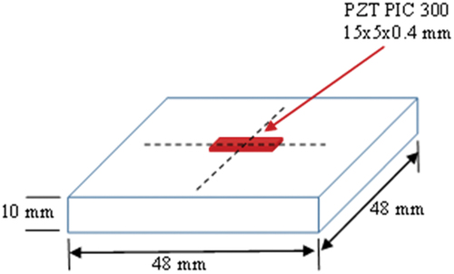
lists the essential parameters of the PZT patch (PIC 300) and the material properties of the host structure.
Table 1. Key parameters of the PZT patch.
Table 2. Key material properties of the host structure.
2.2. Bonding procedure for alloy and adhesive
For bonding, the researchers proposed the Sn-Ag-based alloy bonding as bond layer materials for the first time in structural health monitoring using the EMI technique. The proposed configuration began with the creation of a Sn-Ag alloy-based bond, thermally activated to create a unique bond that provides an intermediate form of bond between rigid and flexible, which ensures better durability and transfer of shear stress between patch and structure (Micro-mesurements, Citation2005). The preparation of the bonding material is complex since it requires mixing Sn-Ag alloy with a small part of epoxy (only 3% of the total alloy mass) and exposing the substrate to high temperatures for a short period of time. Basically, the added Sn-Ag alloy has composition of Tin (93.5%), Silver (3.5 to 4%), and Titanium (3.1 to 4%). represents the lab-sized sample instrumented PZT patch attached through Sn-Ag alloy and wired, ready for data acquisition.
Figure 4. Sn-Ag bonding procedure.
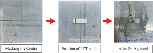
It was further followed by installing the PZT patch once the substrate has reached a suitable temperature for bonding.
The following steps have been taken for proper attachment of Sn-Ag-based alloy bonding:
By utilizing a heat gun at an increased temperature and keeping an eye on the heat, the host structure is heated to thermally activate the Sn-Ag alloy (see ). The heating of the sample to a higher temperature and a partially molten state for the Sn-Ag bonding material is shown in . The sample is heated to a higher temperature using a heating gun, and the surface is continuously monitored by a thermometer to ensure the desired temperature is reached.
Figure 5. Themo-mechanical activation of Sn-Ag alloy.
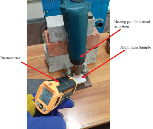
Expose the Sn-Ag alloy to heated host structure in exactly marked bond area. Therefore, the Sn-Ag alloy melts with a slower process and can easily bond.
Add a very small amount of high heat-resistant adhesive to the molten Sn-Ag alloy to obtain a plastic mixture of the Sn-Ag alloy.
Place the PZT patch on the marked bond area of the structure and press it evenly for uniformity
Again cover the whole bond area for 2hrs through thin polyethene. This comprises the whole bonding procedure for Sn-Ag alloy. Later, the soldering wires will join in the electrodes for acquisition signatures via impedance analyzer.
2.3. Sensor integration and data acquisition
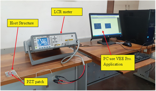
The PZT patch-mounted aluminium blocks further integrated to LCR metre (Agilent 4980A, 30–300 kHz range) and a PC with facilitated interface software (VEE PRO 9.3), shows the complete experimental setup. The conductance and susceptibility of the PZT patches were measured at 100 intervals for the frequency range of 30–300 kHz to obtain the EMI signatures for all specimens. For piezo-impedance-based SHM, Park et al. (Citation2003) proposed a frequency range of 30 to 400 kHz for PZT patches of 5 to 15 mm in size. Signatures were recorded for the PZT patch for both alloy-based and epoxy-based bonding mechanism.
Figure 6. Complete experimental set-up.
To understand the effect for bond curing, three lab-sized aluminium samples were prepared for each case, ie adhesive and Sn-Ag alloy bonding procedure for better comparison (see ). The acquired piezo-coupled admittance signatures for alloy and adhesive bond for curing for continuous 7 days to understand signal stabilization.
2.4. Procedure for bond geometry degradation
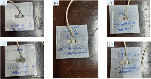
In addition, this study has been extended to investigate geometric bond degradation with the alternation of bond area, that is, 20%, 40%, 50%, and 65% of the total bond area. Aluminium samples of dimensions 48 × 48 x 10 mm were prepared with bond and de-bond areas being estimated and prepared for the same experimental verification (see ). For bonding, the specimen was cleaned in the first phase with methylated spirit and a napkin, and bond area shapes (also for debonding) are marked on the aluminum block. To keep the bond thickness minimum (0.125 mm), a very fine fibre cable kept at the boundary and prepared adhesive is filled in the inner spaces with a needle. A similar procedure is followed for the Sn-Ag alloy bond. For alloy-based bonding, as thermal activation is needed, the gluing action should be very fast. PZT patches placed to the bond region were allowed to cure for a day. After that, the sensors were soldered using a coaxial cable and the wires were secured with additional epoxy. The piezo-coupled admittance was acquired for both types of bonding and debonding through an impedance analyzer. The details of the experiment is shown in , and represent the lab-sized aluminium block instrumented with PZT patch via Sn-Ag alloy and epoxy bond.
Figure 7. Degradation of bond geometry for adhesive bond interlayered between PZT patch and structure.
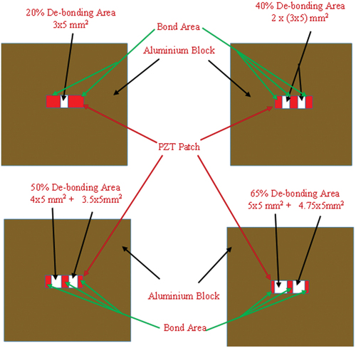
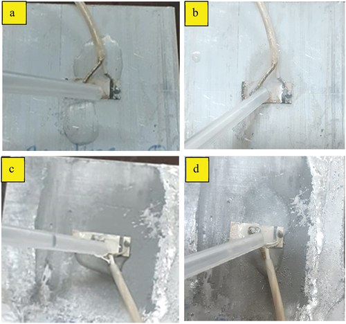
Figure 8. Laboratory-sized aluminium sample instrumented with PZT patch through Sn-Ag alloy bonding. a)complete bonding area b)20% De-bonding c)40 % De-bonding d)50 % De-bonding e)65 % De-bonding.
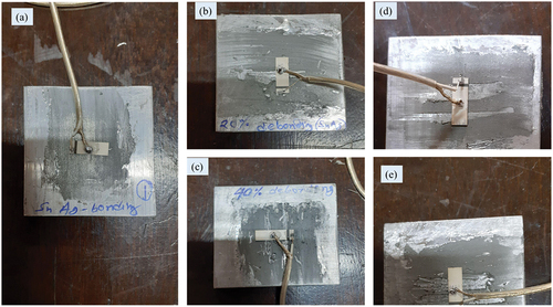
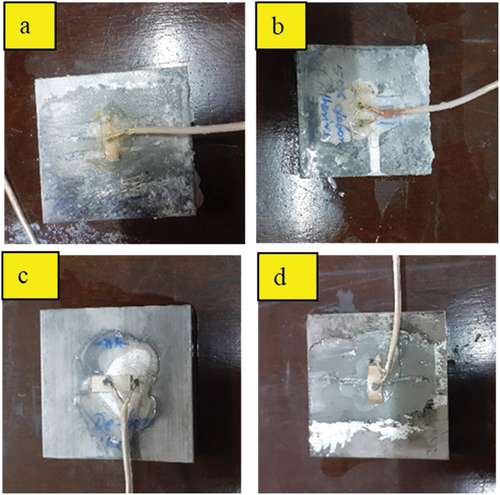
Figure 9. Laboratory-sized aluminium sample instrumented with PZT patch through epoxy bonding. a)complete bonding area b)20% De-bonding c)40 % De-bonding d)50 % De-bonding e)65 % De-bonding.
2.5. Procedure for moisture exposure to Bond Area
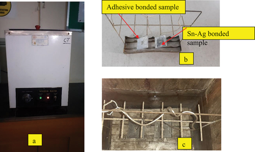
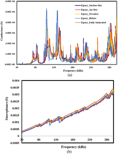
The moisture effect on Sn-Ag-based alloy and epoxy adhesive bonding was investigated through constant immersion and varying moisture conditions of the aluminium sample instrumented with the PZT patch. For constant moisture exposure, the samples were immersed with distilled water for 15 days and signatures were acquired through consecutive days (after 1, 3, 5, 7, 10, and 15 days of immersion in water). The complete experimental setup is shown in . For varying moisture condition, the moisture effect on the bond line has been studied with the help of a water bath for four different conditions, i.e., full saturated (putting the sample in a water bath with boiling temperature), surface dry (slowly dried with cloth), air dry (allow to dry under natural air circulation), and oven dry (kept the sample for 1 h at temp. 80°C). The complete experimental results are shown in .
Figure 10. Moisture curing : specimens immerse in water.
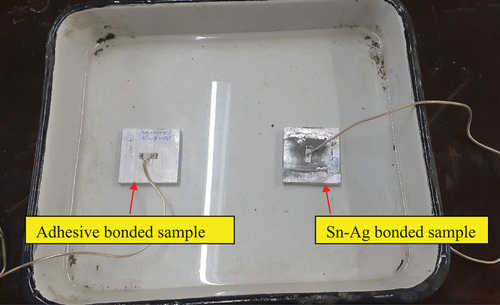
Figure 11. Moisture effect study in a water bath. a) water bath b) aluminum samples with specimen holder c) aluminum samples immersed in a water bath.
2.6. Procedure for temperature exposure to bond area
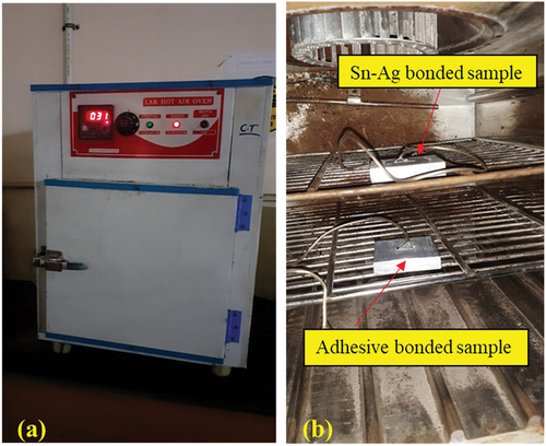
After performing signal repetition tests, the baseline signatures were collected at room temperature (300C) using an LCR meter (Agilent, E4980A) for piezo actuation and sensing. Signatures were used as a baseline signature since they remained the same throughout three readings (Banerjee and Moharana, Citation2022). The temperature range for the lab-sized samples was 50° to 110°C, and the piezo-coupled admittance signature was measured at 10°C intervals. The temperature effect of a bonded PZT patch is shown in in a typical experimental setup. An N-type thermocouple was used to detect the continuous thermal variation in a steel sample kept at 50 ° C to 110 ° C through the data logger.
Figure 12. Study of the temperature effect with the help of the hot air oven. a) oven b) aluminium samples kept in an oven for thermal exposure.
2.7. Procedure for chemical (both acid and alkali) exposure to the bond area
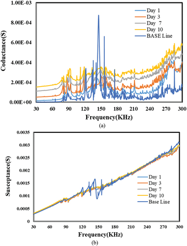
In addition, the researchers investigate the bond degradation because of chemical ingress through bond and its effect on piezo-coupled admittance signature. For the alkali effect, an anhydrous calcium sulfate of concentration 20 g/lit is used to prepare the solvent, and the aluminium samples were exposed to alkali by dropping the solution into the bond area through the dropper for 10 days continuously. In a similar line, acidic (sulfuric acid) solvent concentration of 1.9 g/lit was prepared and dropped to bond materials for 10 days. The chemical exposure procedure is shown in . The signatures were obtained for 1, 3, 7, and 10 days for alloy- and adhesive-based bonding for PZT-mounted aluminium sample.
Figure 13. Chemical test by dropping chemicals. a) acid drop on epoxy bond b) alkali drop on epoxy bond c) acid drop on Sn-Ag-based al alloy bond d) alkali drop on Sn-Ag-based alloy bond.
After completion of the 10th day exposure to alkali and acidic solution, the conductance signatures were obtained and the deterioration is quite visual from the end results (see ).
Figure 14. Degradation of the bond after exposure of 10 days. a) acid effects on the epoxy bond b) alkali effects on epoxy bond c) acid effects on Sn-Ag-based alloy bond d) alkali effects on Sn-Ag-based alloy bond.
3. Results and discussion
As this study proposed, a novel bonding technique for sensor attachment to structure of interest for monitoring and diagnosis is proposed. The piezo-coupled admittance signature has acquired for both the Sn-ag alloy and the adhesive bond and compared with the free PZT signature (see ).
Figure 15. Comparison of the piezo coupled signature for free and bonded configurations. a) conductance vs. frequency. b) susceptance vs. frequency.
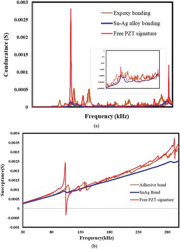
For EMI-based signature, the conductance signature, the piezo resonance peaks for free signature are significantly matching with epoxy bonding approach, but for Sn-Ag alloy, the peaks are little damped, but the frequency values for all three bond conditions (free PZT patch, epoxy, and Sn-Ag alloy) are almost aligned and overlapped (see . For susceptance, the epoxy- and alloy-based bonding have the same susceptance value, which is much lower than the free resonance peak of the free-free PZT patch. This gives the first-hand proof that alloy-based bonding has potential to actuate and sense piezo mechanical deformation for EMI technique as susceptance, majorly reflecting the bond health (see . Overall, satisfactory performance of Sn-Ag based sensor integration is seen through, with a very prominent conductance peak and slope of the susceptance curve. Sn-Ag-based alloy bonding contribute significantly to the influence of bond degradation (20%, 40%, 50%, and 65% debonding) on piezo-coupled admittance characteristics and also studied for the epoxy-based debonding. represent the piezo-coupled signatures for debonding cases. For the Sn-Ag bonding case, it can be seen that with increasing debonding area, the signature peaks are decreasing (shifting left) and attained high conductance values and also are similar to the free PZT patch signature for the highest debonding area (see ).
Figure 16. The effect of bonding and de-bonding on piezo coupled admittance signature for Sn-Ag alloy-based bonding. a) conductance vs frequency b) susceptance vs frequency.
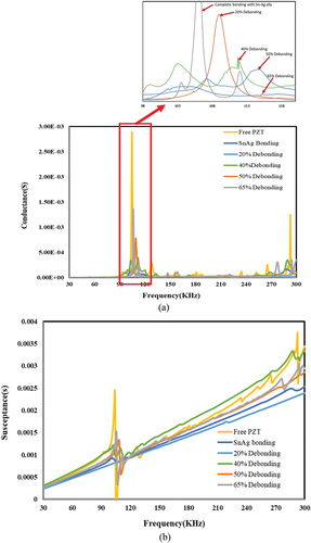
Figure 17. The effect of bonding and de-bonding on piezo coupled admittance signature for epoxy based bonding. a) conductance vs frequency b) susceptance vs frequency.
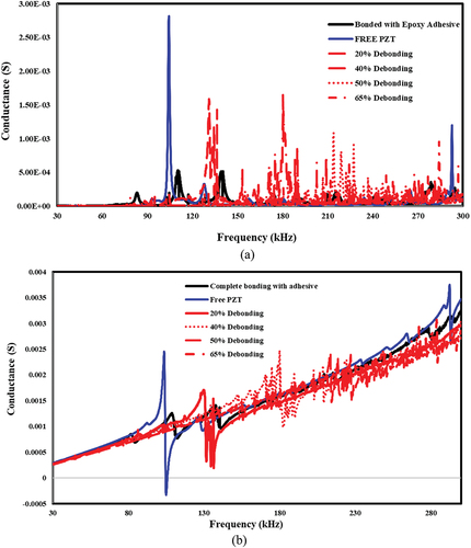
A similar trend is noticed for the susceptance case, and as the debonding area increases, the susceptibility values increase as well and match more with free PZT patch signature (see ).
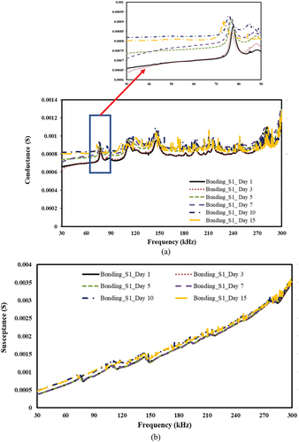
For adhesive bonding, the shifting of piezo resonance peaks for debonding mechanism is not linear, and there is a very random change in peaks values (and frequency) for increasing in bond degradation (see ). In case of susceptance, the variation of peaks shows some trend, ie, decreasing for higher debonding area but not in linear trend as seen in case alloy-based bonding (refer . shows the change in peak value due to debonding for both Sn-Ag and epoxy-based debonding. The change in frequency is quite linear for Sn-Ag case but very consistent for epoxy-based bonding. The above tabulated results signify the rigorous estimation of debonding for EMI-based SHM. For moisture exposure, the signatures were obtained for both constant immersion and variation in moisture content. For constant immersion, the signatures were obtained for consecutive days interval for Sn-Ag bond, represented in . For conductance signatures, the moisture effect has seen through the slope of the conductance curve, but in general, it has very less impact as days progress (refer to the days 10 and 15 curves of ). A little deviation in the conductance curve is observed for the initial days of exposure to moisture. For susceptance, it has no significant variation for any days of exposure (see ), shows better health of bond, and hence the robust electroactive system.
Figure 18. Effect of moisture exposure (constant im mersion) on the Sn-ag alloy-based bond. a) conductance vs. frequency b) susceptance vs. Frequency.
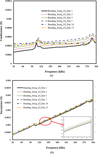
Table 3. Change in structural resonance frequency due to debonding.
For adhesive bonding, the signature variation follows a random pattern and slightly shifts left (see and hardly any variation in susceptance (see . For different variations in moisture content, the effect is very significant.
Figure 19. Effect of moisture exposure (constant immersion) on epoxy-based bonding. a) conductance vs. frequency b) susceptance vs. Frequency.
For alloy-based bonding, the effect is negligible for bond health (see but has potential to alter the conductance signature (i.e., conductance peak value, see ), could represent fictitious alarm in SHM purpose. On the contrary, for adhesive bonding, the effect is significant as it can be seen that the resonance frequency shifts and the conductance value of the structure signatures (both . The above results show the efficiency and durability of the proposed alloy-based bonding technique for SHM application.
Figure 20. Effect of moisture ingression to bond area and corresponding piezo coupled admittance signatures for Sn-Ag alloy bond. a) conductance vs frequency b) susceptance vs frequency.
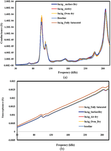
Figure 21. Effect of moisture ingress to bond area and corresponding piezo coupled admittance signatures for epoxy bond. a) conductance vs. frequency b) susceptance vs. Frequency.
Conductance vs. frequency.
Susceptance vs. Frequency.
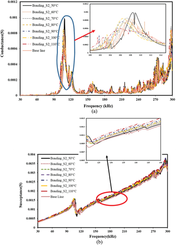
The conductance and susceptance signatures of Sn-Ag based alloy bonds exhibit a negligible change between the base signature and the temperature influenced signature as the temperature rises (see ). For the conductance signature, the influence has some effect (change in frequency and dampened peak value) for increasing in temperature from 50°C to 110°C (see ). There is hardly any change in susceptance signature (refer to ). In the case of an epoxy-based bond, the peak value of conductance has random variation of peak and resonance frequency and does not follow any pattern see ) (Park et al., Citation2003)
Figure 22. Effect of temperature for Sn-Ag-based alloy bond.
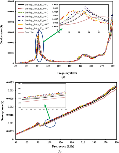
Figure 23. Effect of temperature for epoxy-based bond.
For chemical exposure, samples were exposed to both acid and alkali solutions by constant drop through nozzle drops (20 drops at a time and 4 times a day). Exposure carried out for 10 days continuous. The piezo-coupled signature was taken from sample for the first, third, seventh, and 10th days of exposure and compared with baseline data. For Sn-Ag-based bonding procedure, the conductance signature shows batter stabilization toward acid exposure (see ) and susceptance shows no significant changes at all for acid exposure (see ). For adhesive bonding, the variation of conductance peak vary rapid for each progressive signatures (see ), but susceptance curves show no significant change (see ). The overall results show the great potential of Sn-Ag alloy-based bonding sensor durability against acid exposure and good bond health.
Figure 24. Effect of acid for Sn-Ag-based bond. a) conductance vs. frequency. b) susceptance vs. Frequency.
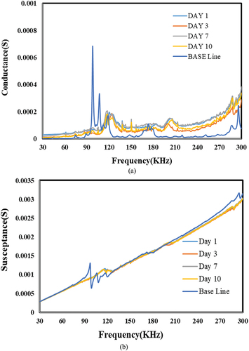
Figure 25. Effect of acid for epoxy-based bond. a) conductance vs. frequency. b) susceptance vs. Frequency.
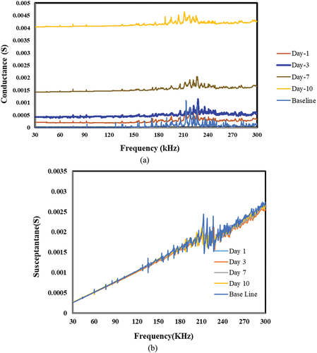
The alkali effect of bond health has been studied through a chemical drop test as an acid effect. For the Sn-Ag bond, though the effect is significant for the conductance signature (see , as the slope and curve of the conductance signature change (not much immediate effect but progressive) but for susceptance there is no change at all, shown better bond health (see ). For the adhesive case, the effect is much significant as the acquired conductance signatures for alkali exposure is very erratic (see ) and higher variation susceptance peak for imaginary of coupled signature (see ). Overall, the variation of signatures for Sn-Ag alloy-based bonding shows promising behaviour toward durability of bond for efficient SHM system.
Figure 26. Effect of alkali for Sn-Ag based bond. a) conductance vs. frequency. b) susceptance vs. Frequency.
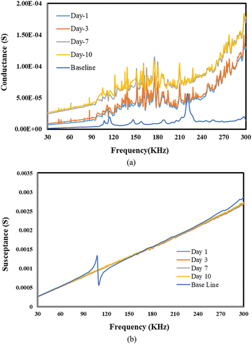
Figure 27. Effect of alkali for epoxy-based bond. a) conductance vs. frequency. b) susceptance vs. Frequency.
4. Conclusions
The present study explored the viability of Sn-Ag-based alloy as a bonding material for sensor integration/attachment with host structure for efficient SHM system. As the interlayer bond between structure and sensor, bonding material plays a significant role for actuation and sensing, also contribute to the coupled mechanism, responsible to reflect the structural properties through signals. Hence, the material suitability and durability of the bonding material are of utmost importance in the SHM system. The Sn-Ag-based alloy bonding shows better performance towards sensor repeatability and stabilization. Further, for the debonding mechanism, the coupled admittance signatures were varied linearly (lower-order alternation) for both conductance and susceptance, whereas the epoxy-based bonding showed a very random variation for the debonding geometry of the interface bond layer. The durability study of the proposed alloy bonding has been performed for moisture and chemical and thermal exposure and has been compared for adhesive bonding. For both moisture exposure duration and embodied moisture content, the Sn-Ag alloy has significant improved performance (negligible change in resonance peaks and frequencies) over adhesive bond. Similar behaviour is reported for both temperature variation shows better thermal stability. For chemical exposure, both for acid and alkali exposure, the variation of conductance for both alloy- and epoxy-based bonding has a very negligible effect, but for susceptance (hence the bond health), the Sn-Ag alloy-based bond has a satisfactory improvement in comparison with epoxy bonding. In general, the proposed Sn-Ag alloy-based bonding technique has more positive advantages in comparison with conventional epoxy-based bonding technique. This new proposed technique can be used for sensor installation in large civil infrastructure where the durability and stability of the bond is a major concern.
Declarations
Conflict of interest on behalf of all authors, the corresponding author states that there is no conflict of interest.
Ethics approval statement
Hereby, the author(s) consciously ensure that for the manuscript “A Novel Approach of Alloy Based Bonding for Piezoelectric Sensor Integrated in Impedance-Based Structural Health Monitoring” the following is fulfilled:
This material is the authors’ own original work which has not been previously published elsewhere.
The paper is not currently being considered for publication elsewhere.
The paper reflects the authors’ own research and analysis in a truthful and complete manner.
Disclosure statement
No potential conflict of interest was reported by the author(s).
Data availability statement
The data sets generated during and/or analysed during the current study are available from the corresponding author on reasonable request.
Additional information
Funding
Notes on contributors
Sk. Ainul Bari
SK Ainul Bari received his M. Tech degree from National Institute of Technical Teachers’ Training and Research, Kolkata. Currently he is doing his doctoral study at Department of Applied Mechanics, Indian Institute of Technology Madars.
Sumedha Moharana
Sumedha Moharana received her PhD degree from Indian Institute of technology Delhi. She is currently an associate professor of Dept. of Civil Engineering at Shiv Nadar Institute of Eminence and interested to carry out research in the field of Structural health Monitoring, Smart material and Improvisation of Concrete durability.
References
- Abuzaid, A., M. S. Dawood, and M. Hrairi. 2015. “Effects of Adhesive Bond on Active Repair of Aluminium Plate Using Piezoelectric Patch.” Applied Mechanics & Materials. translated by Tech Publications Ltd799:788–793. https://doi.org/10.4028/www.scientific.net/AMM.799-800.788.
- Ai, D., and H. Zhu. 2022. “Adhesive Curing Effect of Bonded Piezoelectric Transducer on Electromechanical Impedance-Based Concrete Structural Damage Detection.” Structural Health Monitoring: 1–18. https://doi.org/10.1177/14759217221118514.
- Ali, R., D. R. Mahapatra, and S. Gopalakrishnan. 2004. “An Analytical Model of Constrained Piezoelectric Thin Film Sensors.” Sensors and Actuators A: Physical 116 (3): 424–437. https://doi.org/10.1016/j.sna.2004.05.028.
- Annamdas, V. G. M. 2007. Characterization of smart PZT transducer and admittance signatures using PZT-structure interaction models for structural health monitoring. PhD Thesis, Nanyang Technological University, Singapore.
- Annamdas, V. G. M., and P. Rizzo. 2009. “Influence of the Excitation Frequency in the Electromechanical Impedance Method for SHM Applications.” In Smart Sensor Phenomena, Technology, Networks, and Systems, edited by Norbert G. Meyendorf, Kara J. Peters, Wolfgang Ecke. Vol. 7293. International Society for Optics and Photonics.
- Baker, A. A. 2004. Composite Materials for Aircraft Structures. 3rd. American Institute of Aeronautics & Astronautics.
- Banerjee, T., and S. Moharana, 2022. “Monitoring Thermal Defects in Rail and Rail Joints Using Piezo Impedance-Based Structural Health Monitoring (PISHM).” Engineering Research Express 4 (1): 015014.
- Bhalla, S., A. S. K. Naidu, C. W. Ong, and C. K. Soh. 2002. “Practical Issues in the Implementation of Electromechanical Impedance Technique for NDE.” In Smart Structures, Devices, and Systems, edited by Erol C. Harvey, Derek, Abbott, Vijay K. Varadan, 484–494. Vol. 4935. International Society for Optics and Photonics.
- Blackshire, J. L., and A. Cooney. 2006. “Evaluation and Improvement in Sensor Performance and Durability for Structural Health Monitoring Systems.” In Advanced Sensor Technologies for Nondestructive Evaluation and Structural Health Monitoring II, edited by Norbert, Meyendorf, George Y., Baaklini, Bernd, Michel,137–146. Vol. 6179. SPIE.
- Blackshire, J. L., V. Giurgiutiu, A. Cooney, and J. Doane. 2005. “Characterization of Sensor Performance and Durability for Structural Health Monitoring Systems.” Advanced Sensor Technologies for Nondestructive Evaluation and Structural Health Monitoring, edited by Norbert Meyendorf, George Y. Baaklini, Bernd Michel, 66–75. Vol. 5770. SPIE.
- Chetwynd, D., F. Mustapha, K. Worden, & J. Rongong 2006. Damage Detection in Plates Using Transducers Mounted on Viscoelastic Damping Layers. In Proceedings of the 3rd European Workshop Structural Health Monitoring, Granada Spain. 300–307.
- Civera, M., and C. Surace. 2022. “Non-Destructive Techniques for the Condition and Structural Health Monitoring of Wind Turbines: A Literature Review of the Last 20 Years.” Sensors 22 (4): 1627. https://doi.org/10.3390/s22041627.
- Crawley, E. F., and J. De Luis. 1987. “Use of Piezoelectric Actuators as Elements of Intelligent Structures.” AIAA Journal 25 (10): 1373–1385. https://doi.org/10.2514/3.9792.
- Du, Y., W. Du, D. Lin, M. Ai, S. Li, and L. Zhang 2023. “Recent Progress on Hydrogel-Based Piezoelectric Devices for Biomedical Applications.” Micromachines 14 (1): 167. https://doi.org/10.3390/mi14010167.
- Gandhi, M. V., and B. D. Thompson. 1992. Smart Materials and Structures. Springer Dordrecht: Springer Science & Business Media.
- Guo, Y. Q., J. Zhang, and X. H. Huang. 2019. “The Development and Tests of Remote Data Acquisition and Transmission System on Civil Engineering Structural Vibration.” Journal of Asian Architecture and Building Engineering 18 (1): 9–15. https://doi.org/10.1080/13467581.2019.1585861.
- Han, L., X. D. Wang, and Y. Sun. 2008. “The Effect of Bonding Layer Properties on the Dynamic Behaviour of Surface-Bonded Piezoelectric Sensors.” International Journal of Solids and Structures 45 (21): 5599–5612. https://doi.org/10.1016/j.ijsolstr.2008.06.003.
- Harper, C. A. 2001. “Handbook of Ceramics, Glasses, and Diamonds.”
- Hormadaly, J. 2012. Printed Films: Materials Science and Applications in Sensors, Electronics and Photonics. Elsevier Science.
- Lin, M., and F. K. Chang. 2002. “The Manufacture of Composite Structures with a Built-In Network of Piezoceramics.” Composites Science and Technology 62 (7–8): 919–939. https://doi.org/10.1016/S0266-3538(02)00007-6.
- Micro-Measurements, V. 2005. “Strain Gage Installations with M-Bond 200 Adhesive.” Instruction Bulletin B-127-14:1–4.
- Mittal, K. L., V. A. N. Ooij, W. J., and H. R. Anderson 1998. “First International Congress on Adhesion Science and Technology: Invited Papers : Festschrift in Honor of Dr.” K.L. Mittal on the Occasion of His 50th Birthday, VSP.
- Moharana, S. 2012. “Modelling of Piezo-Structure Elastodynamic Interaction Through Bond Layer for Electro-Mechanical Impedance Technique.”
- Moharana, S., and S. Bhalla. 2014. “A Continuum Based Modelling Approach for Adhesively Bonded Piezo-Transducers for EMI Technique.” International Journal of Solids and Structures 51 (6): 1299–1310.
- Moharana, S., and S. Bhalla. 2015. “Influence of Adhesive Bond Layer on Power and Energy Transduction Efficiency of Piezo-Impedance Transducer.” Journal of Intelligent Material Systems and Structures 26 (3): 247–259. https://doi.org/10.1177/1045389X14523858.
- Mustapha, S., and L. Ye “Bonding Piezoelectric Wafers for Application in Structural Health Monitoring–Adhesive Selection”. Research in Nondestructive Evaluation 26 (1): 23–42.
- Nguyen, B. P., Q. H. Tran, T. T. Nguyen, A. M. Pradhan, and T. C. Huynh. 2021. “Understanding Impedance Response Characteristics of a Piezoelectric-Based Smart Interface Subjected to Functional Degradations.” Complexity 1–24.
- Park, G., D. J. Inman, and C. R. Farrar. 2003. “Recent Studies in Piezoelectric Impedance-Based Structural Health Monitoring.” Structural Health Monitoring 24 (16): 1423–1430.
- Park, G., H. Sohn, C. R. Farrar, and D. J. Inman. 2003. “Overview of Piezoelectric Impedance-Based Health Monitoring and Path Forward.” The Shock & Vibration Digest 35 (6): 451–464. https://doi.org/10.1177/05831024030356001.
- Parpe, A., and T. J. Saravanan. 2021. “New Refined Analytical Models for Various Bonding Conditions of an Adhesively Bonded Smart PZT Transducer Using the EMI Technique.” Smart Materials and Structures 30 (12): 125015. https://doi.org/10.1088/1361-665X/ac32e9.
- Pietrzakowski, M. 2001. “Active Damping of Beams by Piezoelectric System: Effects of Bonding Layer Properties.” International Journal of Solids and Structures 38 (44–45): 7885–7897. https://doi.org/10.1016/S0020-7683(01)00105-6.
- Qiao, L., W. Yan, and S. Cao. 2023. “Inverse Analysis for Damage Detection in a Rod Using EMI Method.” Mechanics of Advanced Materials and Structures 30 (1): 168–174. https://doi.org/10.1080/15376494.2021.2010845.
- Qing, X. P., S. J. Beard, A. Kumar, and R. Hannum. 2006. “A Real-Time Active Smart Patch System for Monitoring the Integrity of Bonded Repair on an Aircraft Structure.” Smart Materials and Structures 15 (3): N66. https://doi.org/10.1088/0964-1726/15/3/N03.
- Qing, X. P., A. Kumar, S. Beard, P. Yu, D. Zhang, C. Liu, & R. Hannum 2006. Advanced Self-Sufficient Structural Health Monitoring System. In Proceedings of the Third European Workshop on Structural Health Monitoring, Granada, Spain, pp. 5–7.
- Saravanan, T. J., and S. S. Chauhan. 2022. “Study on Pre-Damage Diagnosis and Analysis of Adhesively Bonded Smart PZT Sensors Using EMI Technique.” Measurement 188:110411. https://doi.org/10.1016/j.measurement.2021.110411.
- Sbarufatti, C., M. Corbetta, A. Manes, and M. Giglio. 2014. “Real-Time Sequential Monte Carlo Sampling Based on a Committee of Artificial Neural Networks for Residual Lifetime Prediction of a Component Subjected to Fatigue Crack Growth.” Procedia Engineering 74. 347–351.
- Sbarufatti, C., A. Manes, and M. Giglio. 2014. “Application of Sensor Technologies for Local and Distributed Structural Health Monitoring.” Structural Control and Health Monitoring 21 (7): 1057–1083. https://doi.org/10.1002/stc.1632.
- Schubert, K. J., and A. S. Herrmann. 2012. “On the Influence of Moisture Absorption on Lamb Wave Propagation and Measurements in Viscoelastic CFRP Using Surface Applied Piezoelectric Sensors.” Composite Structures 94 (12): 3635–3643. https://doi.org/10.1016/j.compstruct.2012.05.029.
- Singh, S. K., and R. Shanker. 2022. “Determining the Sensing Region of Surface Bonded PZT Sensor and Surface Mounted PZT Sensor in Electro-Mechanical Impedance Technique for Non-Destructive Testing.” Russian Journal of Nondestructive Testing 58 (10): 934–949.
- Sohn, H., C. R. Farrar, F. M. Hemez, D. D. Shunk, D. W. Stinemates, B. R. Nadler, and J. J. Czarnecki. 2002. A Review of Structural Health Monitoring Literature: 1996–2001, 1. USA: Los Alamos National Laboratory.
- Soh, C. K., Y. Yang, and S. Bhalla. 2012. Smart Materials in Structural Health Monitoring, Control and Biomechanics. Springer Science & Business Media. https://doi.org/10.1007/978-3-642-24463-6.
- Srivastava, S., S. Prakash, S. Tripathi, and S. Bhalla. 2023. “Enhancement of Non-Bonded Piezo Sensor Mechanism for Osteoporosis Detection.” In Emerging Trends in Mechanical and Industrial Engineering. Lecture Notes in Mechanical Engineering, edited by X. Li, M. M. Rashidi, R. S. Lather, and R. Raman, Vol. 76 1001–1008. Singapore: Springer. https://doi.org/10.1007/978-981-19-6945-4_76.
- Sun, H., Y. Wang, X. Qing, and Z. Wu. 2018. “High Strain Survivability of Piezoceramics by Optimal Bonding Adhesive Design.” Sensors 18 (8): 2554. https://doi.org/10.3390/s18082554.
- Van den Ende, D. A., B. Bos, W. A. Groen, and L. M. J. G. Dortmans. 2009. “Lifetime of Piezoceramic Multilayer Actuators: Interplay of Material Properties and Actuator Design.” Journal of Electroceramics 22 (1): 163–170. https://doi.org/10.1007/s10832-007-9411-0.
- Veidt, M., T. Liu, and S. Kitipornchai. 2000. “Experimental Investigation of the Acousto-Ultrasonic Transfer Characteristics of Adhesively Bonded Piezoceramic Transducers.” Smart Materials and Structures 9 (1): 19. https://doi.org/10.1088/0964-1726/9/1/303.
- Vodicka, R., and S. C. Galea 1998. “Use of PVDF Strain Sensors for Health Monitoring of Bonded Composite Patches.” In DSTO Aeronautical and Maritime Research Laboratory. DSTO Aeronuatical and Maritime Research Laboratory.
- Wang, L., S. Nagarajaiah, W. Shi, and Y. Zhou. 2021. “Semi-Active Control of Walking-Induced Vibrations in Bridges Using Adaptive Tuned Mass Damper Considering Human-Structure-Interaction.” Engineering Structures 1 (244): 112743. https://doi.org/10.1016/j.engstruct.2021.112743.
- Wang, L., S. Nagarajaiah, W. Shi, and Y. Zhou. 2022. “Seismic Performance Improvement of Base-Isolated Structures Using a Semi-Active Tuned Mass Damper.” Engineering Structures 15 (271): 114963. https://doi.org/10.1016/j.engstruct.2022.114963.
- Wang, L., S. Nagarajaiah, Y. Zhou, and W. Shi. 2023. “Experimental Study on Adaptive-Passive Tuned Mass Damper with Variable Stiffness for Vertical Human-Induced Vibration Control.” Engineering Structures 1 (280): 115714. https://doi.org/10.1016/j.engstruct.2023.115714.
- Wang, L., W. Shi, X. Li, Q. Zhang, and Y. Zhou. 2019. “An Adaptive‐Passive Retuning Device for a Pendulum Tuned Mass Damper Considering Mass Uncertainty and Optimum Frequency.” Structural Control and Health Monitoring 26 (7): e2377. https://doi.org/10.1002/stc.2377.
- Wang, L., W. Shi, Q. Zhang, and Y. Zhou. 2020. “Study on Adaptive-Passive Multiple Tuned Mass Damper with Variable Mass for a Large-Span Floor Structure.” Engineering Structures 15 (209): 110010. https://doi.org/10.1016/j.engstruct.2019.110010.
- Wang, L., W. Shi, Y. Zhou, and Q. Zhang. 2020. “Semi-Active Eddy Current Pendulum Tuned Mass Damper with Variable Frequency and Damping.” Smart Structures and Systems 25 (1): 65–80.
- Wang, L., Y. Zhou, S. Nagarajaiah, and W. Shi. 2023. “Bi-Directional Semi-Active Tuned Mass Damper for Torsional Asymmetric Structural Seismic Response Control.” Engineering Structures 1 (294): 116744. https://doi.org/10.1016/j.engstruct.2023.116744.
- Wang, L., Y. Zhou, and W. Shi. 2023a. “Seismic Control of a Smart Structure with Semiactive Tuned Mass Damper and Adaptive Stiffness Property.” Earthquake Engineering and Resilience 2 (1): 74–93. https://doi.org/10.1002/eer2.38.
- Wang, L., Y. Zhou, and W. Shi2023bSeismic Response Control of a Nonlinear Tall Building Under Mainshock-Aftershock Sequences Using Semi-Active Tuned Mass DamperInternational Journal of Structural Stability and Dynamics org10.1142 S. 2023 Jul 14https://doi.org/10.1142/S0219455423400278
- Wei, C. Y., C. C. Ye, S. W. James, R. P. Tatam, and P. E. Irving, An Experimental Approach to Quantify Strain Transfer Efficiency of Fibre Bragg Grating Sensors to Host Structures, The 13th International Conference on Composite Materials ICCM-13, Beijing, China, June 25-29, 2001.
- Winston, H. A., F. Sun, and B. S. Annigeri. 2001. “Structural Health Monitoring with Piezoelectric Active Sensors.” Journal of Engineering for Gas Turbines and Power 123 (2): 353–358. https://doi.org/10.1115/1.1365123.
- Xu, X. H., and J. R. Chu. 2008. “Preparation of a High-Quality PZT Thick Film with Performance Comparable to Those of Bulk Materials for Applications in MEMS.” Journal of Micromechanics and Microengineering 18 (6): 065001. https://doi.org/10.1088/0960-1317/18/6/065001.
- Zagrai, A. N., and V. Giurgiutiu 2001. “Electro-Mechanical Impedance Method for Crack Detection in Thin Plates.” Journal of Intelligent Material Systems and Structures 12:709–718.
- Zhang, H., L. Wang, and W. Shi. 2023. “Seismic Control of Adaptive Variable Stiffness Intelligent Structures Using Fuzzy Control Strategy Combined with LSTM.” Journal of Building Engineering 78:107549. https://doi.org/10.1016/j.jobe.2023.107549.
- Zhili, L., H. Lei, W. Yunxin, & Z. Jue 2005. Experiment Study of Temperature Parameter Effect on Bonding Process and Quality in Thermosonic Wire Bonding. In 2005 6th International Conference on Electronic Packaging Technology, Shenzhen, China. 408–413. IEEE.
- Ziss, D., J. Martín-Sánchez, T. Lettner, A. Halilovic, G. Trevisi, R. Trotta, and J. Stangl. 2017. “Comparison of Different Bonding Techniques for Efficient Strain Transfer Using Piezoelectric Actuators.” Journal of Applied Physics 121 (13): 135303. https://doi.org/10.1063/1.4979859.