ABSTRACT
This article deals with the topic of void as a design instrument and theory in architectural design, with a focus on Rem Koolhaas and his specific void design approach. The primary goal is to examine Koolhaas’ perception and usage of void as a design element to continue his theory of the Strategy of the Void I and II by creating some novel design strategies similar to his. To achieve this, the topic of void was broadly analyzed, reaching from the analysis and interpretation of various writings and theoretical works to four pivotal void-projects from Koolhaas. As a result, a genealogy surrounding Koolhaas’ Strategy of the Void I and II has emerged alongside four distinct design strategies which are named after their used void design action of (a) juxtaposition, (b) superposition, (c) cutting, and (d) excavating. Each of these strategies can be used to create a specific design outcome such as (a) an overarching concept, (b) a connection between entities (circulation), (c) architectural spaces, and (d) a contrast. Moreover, it was found that the former two strategies can be categorized as preceding and the latter two as proceeding void design strategies in relation to Koolhaas’ original ones.
1. Introduction
The usage of void as a design instrument in architectural design is rather unusual, with many architects focusing more on the built than the unbuilt matter. Hence, the usage of void as a design method is a relatively unexplored field compared to the use of its counterpart, the solid. This phenomenon does not only apply to architectural practices, but also to researches and theories regarding void as a design method – and basically the topic of void in general. In this regard, the investigation of the void as a design method has the potential to uncover new design approaches that can be flexibly used due to the void’s unique design features.
An architect who often uses void in his designs, a kind of pioneer of void design, is Rem Koolhaas. Besides using void in his own designs to create unique buildings, Koolhaas also published a lot of theoretical writings surrounding the topic of void and its usage as a design method. This includes, for example, the manifesto S,M,L,XL (Koolhaas Citation1998b), where projects and writings such as the Très Grande Bibliothèques (TGB), the Ville Nouvelle Melun-Sénart, and The Berlin Wall are presented. Another publication from Koolhaas is the book called Content: Perverted Architecture (Citation2004), where the well known Strategy of the Void I and II (SotV I+II) are presented. Especially the latter ones are a very interesting approach of Koolhaas to illustrate the usage of void as a design method, which he, however, did not continue so far, meaning that those two strategies remain the only ones published until today. Additionally, these two publications, among others, further show that Koolhaas investigated the topic of the void very early on in his career.
For example, one of his earliest investigations of the void was in 1971, when he researched the Berlin Wall for his studies at the AA in London, which he describes in S,M,L,XL (Koolhaas Citation1998b, 212–233) in the essay “Field Trip.” There, he linked the wall to a type of void, describing it as “a freshly created absence” (p. 228). After that, in 1977, the topic of the void reappears in Koolhaas and Ungers’ theory The City in the City. Berlin: A Green Archipelago (Ungers Citation2013) where the so-called “greenbelts” that float between the city islands can be seen as the void. Lastly, one year later, in 1978, Koolhaas picked up the topic of the void once again, but this time in his own manifesto, Delirious New York (Koolhaas Citation1994). Specifically, the chapter “The Frontier in the Sky” can be related to the void, where he elaborates on the skyscraper and describes it, for example, as creating urban indeterminacy or programmatic instability (pp. 82–109).
Based on these circumstances, the focus is set on the investigation of void as a design instrument and strategy, which is grounded on the works of Koolhaas and his void design approach. The main question is, how does Koolhaas perceive void as a design element and specifically makes use of it. Thereby, the main goal is to continue Koolhaas’ theoretical work of the SotV I+II by establishing some new strategies. These strategies should not only contribute to the rather scarce research in terms of void design, but more so give directly some practical approaches that could also be used in other fields, such as urban design. To achieve this, a project analysis of four pivotal void-projects from Koolhaas is carried out that builds the foundation of this article.
Overall, the study is structured in five main sections, beginning with Section 2 which revolves around the theory of void. In this section, the importance of void is first shown on the basis of Koolhaas’ writing the “Typical Plan.” Afterward, the focus is set on Koolhaas’ void design approach that is illustrated based on the so-called genetic modification and the SotV I+II. The subsequent project analysis in Section 3 builds the main part of this research. There, four projects from Koolhaas – built and unbuilt ones – are analyzed in detail, which comprise the Parc de la Villette, the Agadir Hotel and Convention Center, the 2 Bibliothèques Jussieu, and the Seattle Central Library. Each of these projects is supplemented by an additional one that follows a similar design strategy. The following Section 4 synthesizes the outcome of the project and theory analysis in two parts. In the first part, a genealogy surrounding Koolhaas’ SotV I+II is presented which not only includes his strategies, but also some inspirational projects as well as four new void design strategies-two preceding and two succeeding strategies in relation to Koolhaas’ original ones. Moreover, a classification scheme for the succeeding strategies is proposed. In the second part of this section, the four new void design strategies are presented and explained in detail. Lastly, Section 5 wraps up the paper by taking a look back on the most important findings, including some future research topics regarding void design as well as the limitations of the study.
2. Theory of void
At the beginning of this section, Koolhaas’ writing of the “Typical Plan” is analyzed to illustrate the impact and significance of the void as a design element. Although the “Typical Plan” normally does not refer to void it can be related to it, especially when viewing it in a larger context that includes other writings from Koolhaas such as “Imagine Nothingness,” the “Generic City,” and “Junkspace.” The analysis shows that the void does not only affect the building itself, but more so that it has a direct impact on the city, which means its investigation is of great importance for urban planning, design, and the longevity of the city in general. Afterward, a closer look at Koolhaas’ specific void design approach is taken, which is based on the investigation of two design strategies from him: the genetic modification and the SotV I+II.
2.1. The importance of void: Koolhaas and the typical plan
2.1.1. The typical plan: its essence
In S,M,L,XL, Koolhaas (Citation1998b, 334–353) investigates the issue of the so-called typical plan. He defines such plans as “zero-degree architecture, architecture stripped of all traces of uniqueness and specificity” (p. 335), which he further relates to office buildings. However, the mentioned issues of this phenomenon can not only be related to office buildings but also to the design with void in modern architecture when analyzed and viewed from the perspective of solid and void, which is shown below.
In the chapter surrounding the topic of the typical plan, Koolhaas asserts this phenomenon as an American invention, which was developed in “the late 19th century to the early 1970s … from the primitive loft type (ruthless creation of floor space through the sheer multiplication of a given site) via early masterpieces of smooth space” (p. 336). In this regard, buildings of smooth space such as the World Trade Center, the RCA Building, and the Exxon Building are mentioned. According to Koolhaas, the typical plan’s intention was to create an “ideal accommodation for business” (p. 337). He continues that the program of business is “the most formless” (p. 337), which makes such buildings a representation of “totally abstract program” (p. 337) without the need of a specific architecture. Further, he characterizes this type of program with the sole function where the occupants only exist in. In his conclusion, this leads to that business can basically be applied to any type of architecture. This indeterminacy, as stated by Koolhaas, finally results in the generation of character for the typical plan.
In terms of the typical plan’s characteristics, Koolhaas defines it as being “neutral, not anonymous” (p. 340), which has impure zones (e.g., restrooms, service stairs, pantries, etc.) and exalted zones (business). He further states that the former, which he also describes as being primitive, are basically just there to serve the latter ones to function. Afterward, Koolhaas mentions a first characteristic of the typical plan, which he describes as being a “relentlessly enabling, ennobling background” (p. 341). However, Koolhaas mentions two other characteristics that coin the typical plan, which are namely the “repetition” and “indeterminacy.” According to him, these two characteristics lead to buildings that consist of one and the same floor, which are mostly undefined. Lastly, in terms of the plan’s layout it is stated that the “Typical Plan is as empty as possible” (p. 344), which just consists of “a floor, a core, a perimeter, and a minimum of columns” (p. 344). In short, he describes this simplicity of the plan as being all “about exclusion, evacuation, non-event” (p. 344).
Lastly, Koolhaas expands on the consequences of the typical plan’s vacancy, which he identifies as leading to density. He further states that the typical plan started to change the urban environment through its immense accumulation – the emergence of skyscrapers. According to him, this has also led to a “downtown, defined by sheer quantity rather than as a specific formal configuration” (p. 345) with city centers that are not unique anymore. In addition, he describes this phenomenon as “a conceptual leap: an absence of content in quantities that overwhelm, or simply preempt, intellectual speculation” (p. 345).
2.1.2. The typical plan and void: programmatic indeterminacy, junkspace, and the generic city
At first glance, from Koolhaas description and from the plans, the typical plan seems empty; however, it is not. It basically contains invisible matter, the program, which is in this case related to business. Speaking of emptiness and program, Koolhaas (Citation1998b, 199–203) came to a similar conclusion in his essay “Imagine Nothingness” after elaborating about different urban projects—e.g., the Central Park, The Manhattan Grid, Pompeii – that emptiness (the void) does not have to mean empty. He stated that “they all reveal that emptiness in the metropolis is not empty, that each void can be used for programs whose insertion into the existing texture is a procrustean effort leading to mutilation of both activity and texture” (p. 202). As seen from this statement, emptiness does not equal empty, which is surely the case in the typical plan. It further suggests that the emptiness (charged void) has some effects, which is also the case in the typical plan.
Speaking of effect, the effect of the typical plan actually becomes clear when analyzing Koolhaas’ description of it, meaning that its impact is not simply limited to the plan itself, but rather goes beyond its boundary and directly impacts the city. In particular its effect is, as mentioned by Koolhaas, to create city centers without any uniqueness due to the massive accumulation of buildings that consist of typical plans. Said phenomenon not only shows the effect of the typical plan, but also that there is a connection between a building’s floor plan and its exterior – in this case the city. In this sense, the floor plan basically directly affects the city, which illustrates how big of an impact a floor plan can potentially have. Responsible for this are, of course, the repetition and indeterminacy of the typical plan, which Koolhaas has mentioned.
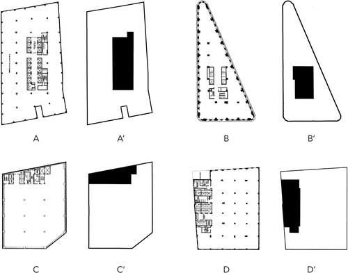
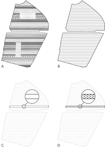
By analyzing the typical plan in more detail regarding solid and void, including the information mentioned above, it can be said that the plan consists of three components (): (1) the facade, which can be defined as the boundary; (2) the core, which can be defined as the solid; and most importantly (3) the so-called business space, which can be defined as the void. These components are very similar to the ones that Koolhaas identified; however, each of these elements serves a distinct purpose in the typical plan. For example, the facade (boundary) frames the floor plan and the void. Through this, it defines the building and its border. The core (solid), such as toilet, storage, stair, elevator, etc., is mostly inside the boundary (facade) or directly attached to it, which, as mentioned by Koolhaas, primarily exists to serve the business space (void). Lastly, the business space (void), or the program, is bounded by the facade (boundary) and pierced by the core (solid), which is the predominant element in this ensemble that functions as the main space.
Figure 1. Solid and void analysis of typical plans with the original plan on the left (A, B, C, D) and the analysis on the right (A’, B’, C’, D’) that shows the three basic elements of which the typical plan consists of Source: Koolhaas Citation1998b, 336, 337, 338, 341 (A, B, C, D, respectively); graphics by author on the basis of the previously mentioned plans (A’, B’, C’, D’).
As a result, it can be noted that Koolhaas’ mentioned problems of programmatic indeterminacy that the business space produces can be attributed to the void, meaning that the void is basically responsible for creating the issues surrounding the typical plan. In this regard, it can further be said that the void’s indeterminacy produces what Koolhaas (Citation2002, 175–190) terms as so-called junkspace – a kind of useless space that is generated through different conditions. As Koolhaas says: “Junkspace can either be absolutely chaotic or frighteningly aseptic … overdetermined and indeterminate at the same time” (p. 179). As seen, junkspace for him is essentially space that lacks the middle-ground, meaning that it is either over or under defined – the latter which applies to the void in the typical plan.
In this sense, it can be said that if the typical plan produces junkspace and is directly responsible for the creation of Koolhaas’ mentioned non-unique city centers, whose space is then basically also just junkspace, the typical plan is further a catalyst for the creation of so-called generic cities, which are essentially, according to Koolhaas (Citation1998b, 1238–1267), standardized metropolises without any unique character. As seen, when the business space is regarded as void, it has not only a huge impact on the floor plan (creation of junkspace), but also on the urban environment (creation of generic cities). What this exactly means is investigated more in the following subchapter.
2.1.3. From building-void to city-void: typical plan as a portrayal of the city and its consequences
As mentioned above, the typical plan’s consequences go way beyond the boundaries of the individual building and directly impact the city, which implies a connection between floor plan and city. This phenomenon essentially means that the floor plan functions as a portrayal of the city, or vice versa. A similar condition described Ungers (Citation1963, 281) in his article to the project «Neue Stadt» in Köln, where he stated that the city is governed by the same formation laws as the individual house, the sum of which it is composed of. He added that the structure of the city is based on the structure of the house, just with different dimensions. In this light, the connection between floor plan and city would suggest that the urban planning issues which the typical plan generates – the non-unique city centers, junkspace, or generic cities – also need to be investigated on the scale of the individual buildings due to their direct impact onto the city. This further implies that the void which the typical plan generates is also connected to the city’s void.
Regarding architecture nowadays, this means that, for example, issues in urban planning and design should also be investigated on the scale of the individual building and their floor plans. Moreover, this also applies to theories surrounding the topic of solid and void that should address said phenomenon, meaning that, for example, the floor plan’s impact onto the city needs to be incorporated in discussion like Rowe and Koetter’s (Citation1978) figure – ground theory in Collage City as well.
2.1.4. Typical plan and void: synthesis
The analysis above has shown that Koolhaas’ theory regarding the typical plan can be directly linked to void, which is embodied in two elements, each with a specific characteristic.
The first element that can be linked to void is the business space. In the solid and void floor plan analysis of it was shown that the typical plan consists of three elements. In said analysis, the business space – essentially the program – functions as the void which exhibits the characteristic of programmatic indeterminacy that ultimately leads to so-called junkspace and generic cities.
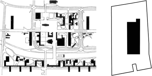
The second element that can be linked to void is the urban environment. It was mentioned by Koolhaas that the urban environment is coined by an immense amount of typical plans (skyscrapers) that lead to non-unique city centers without any precise formal configuration. Said urban environment, the city center’s space, can also be seen as a void due to the connection of floor plan and city, which can here be defined as exhibiting the characteristic of “indeterminacy of formal configuration” – a trait that basically stems from the typical plan’s programmatic indeterminacy. Speaking of connection, the suggested inherent connection between floor plan and city can finally be termed as “inside-out-effect.” This term basically describes an element that comes from the floor plan – here the void – and is transferred onto the city (). Thus, the floor plan essentially functions as a portrayal of the city, or vice versa.
Figure 2. Allegory of the hypothetical connection between city and floor plan: Le Corbusier’s Saint-Dié (left) and the typical plan (right). Source: Rowe and Koetter Citation1978, 62 (left); graphic by author on the basis of Koolhaas Citation1998b, 336 (right).
Lastly, the implications of the above-mentioned connection between floor plan and city are that theories, analyses, and design methods regarding solid and void can be examined on the building and urban level, meaning that gained knowledge from each scale can be subsequently applied to either one. Moreover, this connection allows to further investigate the topic of void, meaning that it is not only possible to learn more about the topic in general and the voids’ characteristics, but more so that it is possible to create novel ideas regarding the design with void. In this case, the research about the void in design is particularly promising, as it has the potential to create flexible designs, such as buildings or urban environments, due to the void’s special design features – the latter, which are shown in more detail in the project analysis (cf. Section 3).
2.2. Koolhaas’ void design approach
This section investigates Koolhaas’ void design approach, which is grounded on two different theories: the genetic modification and the SotV. Thereby, it is shown how Koolhaas perceives void and specifically makes use of it as a design instrument.
2.2.1. Genetic modification
In the previous section (cf. Section 2.1.) it was shown that the business space (the program) essentially functions as the void element in the typical plan, whereby it can be said that also Koolhaas perceives business – the program and its space – as a type of void based on his description. In this regard, hypothetically speaking, the program itself can be defined as being a type of void, which opens up some new and interesting perspectives in terms of the design with void.
To further investigate the hypothetical connection of program and void, as well as its potential use as a design strategy, this part takes a closer look at the so-called genetic modification of Koolhaas, which Lucan, (Citation2012, 559–561) has investigated in his book Composition, Non-Composition: Architecture and Theory in the Nineteenth and Twentieth Centuries. Although Lucan studied this phenomenon more in relation to composition, the genetic modification offers an interesting approach in terms of void design in relation to program when viewed from a different perspective.
In the chapter “Process and Program Versus Composition – Rem Koolhaas,” Lucan mentions Koolhaas’ often used design method, which “had to do with the development of a program in which the introduction or modification of a parameter could steer a project in a new direction” (p. 559). In this regard, he presents the projects Seattle Library and the Bibliothèques de Jussieu – both projects are analyzed in detail in Section 3.4. and 3.3., respectively – which make use of such modifications in terms of their floors’ superposition. As mentioned, this is done at the Seattle Library “‘by genetically modifying the superposition of floors in the typical American high-rise’” (as cited in Lucan, p. 559) and at the Bibliothèques de Jussieu by the “modification of the parameters of superposition of a building’s floors” (p. 559). Further, it is described that the modification at the Seattle Library leads to “one level never exactly superposed on the other” (p. 559), and at the Bibliothèques de Jussieu to the “introduction of general continuity in sloping planes” (p. 559). After the presentation of these genetic modification examples, Lucan concludes that “the genetic modification of which Koolhaas spoke assimilated the architectural project not to a composition, but rather to a series of operations following one after the other in accordance with a program” (p. 559).
According to Lucan’s conclusion, Koolhaas’ genetic modification is essentially a design method that uses multiple operations which are directly linked to a program, such as the mentioned superposition of floors. In this sense, it can be said that the genetic modification is not only the superposition of floors, but also the superposition of program. Moreover, this means that if the program is regarded as void, like initially hypothesized, the genetic modification can essentially be defined as the superposition of void. This hypothetical connection between the program and void which is assumed here is further shown, and supported, in the project analysis later on in this article (cf. Section 3.3. and 3.4.).
Summarized, it can be said that Koolhaas uses the genetic modification – the modification of certain parameters in correlation with the program – as a type of void design strategy, which is in the case of the Seattle Library and the Bibliothèques de Jussieu the superposition of floors that is linked to the program. This strategy not only shows the diversity of Koolhaas’ design approach, but also the void’s diverse field of application. However, beside the genetic modification, there are other void design strategies from Koolhaas such as the SotV I+II, which are much more straightforward and that do not need a prior analysis to be revealed. To further show the diversity of void design and to give another perspective of Koolhaas’ void design methods, these two strategies are subsequently analyzed.
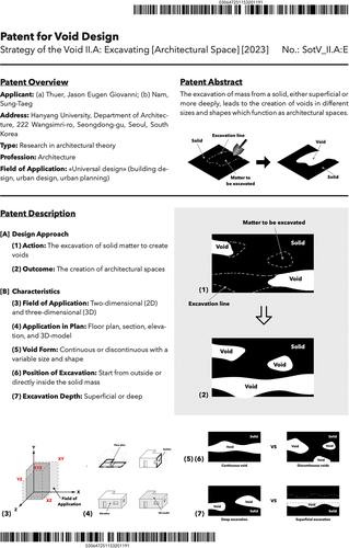
2.2.2. Content: strategy of the void I and II
The SotV I+II are two well known illustrations from Koolhaas regarding the design with void (). Originally, the strategies were published in the chapter “Patent Office” in the book Content: Perverted Architecture (Koolhaas, McGetrick and OMA-AMO, Citation2004, 74 & 77). Said chapter contains various design strategies from Koolhaas’ work, which are illustrated as so-called “Universal Modernization Patents.” In these, the core idea, or in other words the design philosophy, of the specific projects are shown. Among these patents are also the prior mentioned SotV I, which is based on the project Ville Nouvelle Melun-Sénart, and SotV II, which is based on the project TGB.
Figure 3. SotV I (left) and SotV II (right) patents that are published in Content. Source: Koolhaas, McGetrick and OMA-AMO, Citation2004, 74 & 77, respectively.
In general, the void design patents illustrate the projects’ specific idea of void design, which means that they essentially show how Koolhaas perceives and uses void as a design instrument in his design process. Besides this, the patents make clear how important of a design factor void can be due to its diverse usage in the design process, allowing to create some unique designs with it. For example, the patent SotV I – entitled as planning – describes the pursued void design strategy at Ville Nouvelle Melun-Sénart as the “method for planning city through manipulation of the unbuilt and the left out” (p. 74). In contrast, the patent SotV II – entitled as building – describes the pursued void design strategy at TGB as the “method for defining a building through manipulating absences of building” (p. 77).
As seen, both strategies target a completely different field of application, which means that Koolhaas’ perception of void is extremely diverse. For example, at Melun-Sénart, he uses the void as a design instrument in urban design, whereas at the TGB, he uses the void to design a building. These two different applications of the void show that he perceives void as a design instrument that can be used in various settings, which means that it is not bound to a particular field, such as building design or urban design, but rather can be used very flexible in multiple environments. Furthermore, the patents do not only show Koolhaas’ design approach, but also indicate in a sense his attempt to start a theoretical work which focuses on the usage of void as a design strategy. However, apart from these two strategies, Koolhaas did not publish any more of them to date. But, due to the strategies being termed as “one” and “two,” they imply to be a part of a bigger whole, and therefore they can also be regarded as such. In this light, the present research builds upon these two strategies by viewing them as the beginning, and part, of a larger theoretical work in terms of void design whose primary goal is to show how to design with void, and which additionally gives insight into Koolhaas’ specific design practice and perception of void.
To sum up, the SotV I+II patents can be regarded as a portrayal of Koolhaas’ void design philosophy and technique, both of which can be described as being extremely diverse. Furthermore, these two strategies should not only be regarded as isolated objects about the design with void, but rather as a small part of a greater whole – a theory regarding void design – that has not been uncovered yet but which would allow to better understand Koolhaas’ void design approach and the design with void in general.
3. Project analysis
This section analyzes four pivotal projects from Koolhaas regarding their void design approach. The goal is to work out the projects’ specific void design methods which will serve as the basis for the new void design strategies. The analyzed projects are (a) the Parc de la Villette, (b) the Agadir Hotel and Convention Center, (c) the 2 Bibliothèques Jussieu, and (d) the Seattle Central Library. Each of these projects is supplemented by an additional project that uses a similar design technique: (a) the Ville Nouvelle Melun-Sénart, (b) the TGB, (c) the McCormick Tribune Campus Center, and (d) the Zentrum für Kunst und Medientechnologie (ZKM).
Regarding the project selection, the reason to select the four main projects for the analysis was due to their obvious connection to the design with void as well as their different design approaches. Besides these two criterions, the diversity of the projects was very important. The intention of selecting projects that have different characteristics was to be able to examine a lot of diverse information regarding void design, with the goal to create a solid foundation for the subsequent theory – the void design strategies – and to show the potential of void design in general. To achieve this, four parameters were taken into consideration from which at least one had to be different: the scale (buildings vs. urban designs), the design state (built vs. unbuilt), the design approach (focus on floor plan vs. section), and the function (e.g., park, library, office, etc.). According to these parameters, the projects were selected where each project has at least one parameter that is different compared to the other projects.
Lastly, the reason for selecting the supplementary projects was to back up the main projects’ examined void design approach, meaning that their void design approach should match, or be at least close to, the one of the main project. However, it was again crucial that at least one of the above-mentioned parameters had to be different. In addition to that, it was important to include the original SotV I+II – the Ville Nouvelle Melun-Sénart and the TGB – because they basically are the catalyst for this theoretical work and therefore an important part that should be included.
3.1. Parc de la Villette
In S,M,L,XL, by Koolhaas (Citation1998b, 894–935), the project Parc de la Villette is entitled “Congestion Without Matter.” According to Koolhaas, the project is a competition design from 1982 in Paris, France, which he describes in five steps: (1) “Initial Hypothesis,” (2) “The Strips,” (3) “Point Grid, or Confetti,” (4) “Access and Circulation,” and (5) “The Final Layer.”
In the initial hypothesis, Koolhaas states that the project site was too small to inhabit all the required program to design a park. To take this observation and other factors into account, he mentioned that the proposal was to create a design “that combines architectural specificity with programmatic indeterminacy” (p. 921). The core of this proposal, according to Koolhaas, is to gain the most out of the implantation of activities on the site while still providing a so-called “stable aesthetic experience” (p. 921). Further, it is mentioned that the proposal’s programmatic indeterminacy allows change, which does not harm the mentioned hypothesis. Lastly, he points out that important for the project is the question of how to set up “the most dynamic coexistence of activities x, y, and z” (p. 921) to create with their interference novel events which he also terms “social condenser” (p. 921). In addition, it is mentioned that this is achieved by the superimposition of the park’s different layers.
The first layer that Koolhaas describes are “The Strips.” He describes that the first step was to subdivide the entire site into parallel bands (east-west), which inhabit the main program (e.g., 50% of the playgrounds, theme gardens, etc.). It is said that this procedure allows the distribution of the bands in either random or logical order without programmatic clustering. As further mentioned, the strips’ standard width is 50 meters, which can even get further divided, so they can “facilitate change and replacement without disruption and to create fixed points for the infrastructure” (p. 923). In terms of program, it is said that nature is also considered as program. Lastly, Koolhaas mentions the similar experience of the project’s layering to the one of a high-rise building’s superimposed floors and their possibility to facilitate various events: “all contributing to a summation that is more than the accumulation of parts” (p. 923).
The second layer that Koolhaas describes is called “Point Grids, or Confetti.” It is said that this layer consists of smaller programmatic elements (e.g., 50% of the playgrounds, kiosks, picnic areas, etc.), which are distributed across the site as point grids according to their preferable density by a mathematical formula.
The third layer, according to Koolhaas, is called “Access and Circulation,” which consists primarily of two elements: “the promenade” and “the boulevard.” As he mentions, the boulevard runs in north-south direction across the site, which crosses every band and connects several architectural complexes. In addition, it is said that the boulevard also contains all the 24-hour program elements. In contrast, according to Koolhaas, the promenade is the boulevard’s complementary element, which “is generated through the identification and subsequent demarcation – in the form of plazas – of certain significant cross sections through the bands” (p. 927). In addition, he calls these plazas “‘sites within the site’” (p. 927), which contain further programmatic elements such as chess tables, small amphitheaters, tribunes, etc.
Lastly, Koolhaas mentions the so-called “Final Layer,” which “is a composition of the major elements – added and found – that are unique or too large to be located according to mathematical rules or to a system” (p. 929). It is said that these elements are intermediate-sized, which comprise, for example, the Rotonde des Vétérinaires, the Science Museum, or the Ariane. In addition, it is mentioned that the whole composition consists of several architectural elements like, for example, a music zone or reception square with baths.
Overall, the project illustrates an interesting approach of how to design with void. When it comes down to solid and void, the primary void design element in the project can basically be defined as the first layers’ bands/strips that run across the whole site of la Villette (). Characteristic for them, as mentioned by Koolhaas, is that they are filled with various types of programs as well as exhibiting the programmatic indeterminacy that was made in his initial hypothesis, which means that the program can change later on. In this regard, the voids (bands) basically function as a flexible vessel for the programmatic elements that are distributed onto the bands and which can therefore be seen as the solids in this configuration ().
Figure 4. Solid and void analysis of the Parc de la Villette: (A) original plan of the park; (B) voids: bands without programmatic elements (solids); (C) single void: isolated band; (D) solids and void: programmatic elements (solids) on a band (void). Source: Koolhaas Citation1998b, 923 (A); graphic by author on the basis of A (B – D).
In terms of void design technique, to create the bands (voids), Koolhaas has described that the site of la Villette was subdivided. This means, that the site functions as a kind of boundary where the subdivision is performed to create the individual bands, so the method to create the voids can actually be defined as the usage of the design action called “subdivision.” In contrast, the positioning of the voids closely next to each other indicates the pursued design approach (strategy), which can be defined as the “juxtaposition” of voids.
A similar design approach of juxtaposing voids can be seen from Koolhaas’ project Ville Nouvelle Melun-Sénart. The project, as described by Koolhaas (Citation1998b, 972–989), consists of two primary elements, the so-called “bands” and “islands.” As mentioned, the bands, also termed as “linear voids,” form together a “Chinese figure,” whereby the islands “are the counterforms of the surrounding voids” (p. 983). Moreover, in Content, by Koolhaas, McGetrick, and OMA-AMO (Citation2004, 74), the project Melun-Sénart is termed as “Strategy of the Void I” (cf. Section 2.2.2. for patent), which uses the “method for planning city through manipulation of the unbuilt and the left out” (p. 74).
When it comes down to void design, Melun-Sénart and la Villette’s design approaches are quite similar. For example, in both projects, the voids are described as bands with only the solids – islands versus programmatic elements – being different. Moreover, the voids in both projects can be characterized as being juxtaposed on a given site, or playing field, whose borders essentially function as a boundary where the voids are generated within. Specifically, this means that at Melun-Sénart, the bands are juxtaposed in such a manner that they form a figure (Chinese figure) which partly covers the site, whereas at la Villette, the bands are juxtaposed in such a way that they basically form a void-carpet which covers the entire site. As seen from these two examples, both projects use the design technique of juxtaposing voids similarly. However, one key difference between the projects exists: the method of how the voids are generated.
At Melun-Sénart, the method to create the voids was described by Koolhaas as: “instead of projecting onto the landscape, we deducted from it … through this process of elimination, we arrived at an almost Chinese figure of void spaces that we could protect from contamination by the city” (p 977). This means that the used method to create the voids can be described as “deducting” certain valuable areas from the landscape. In contrast, la Villette uses the prior mentioned method of “subdivision” to create the voids. Thus, it can be said that the void generation method can be different (deduction vs. subdivision) while the design technique, in this case the juxtaposition of voids, is still the same.
3.2. Agadir Hotel and Convention Center
According to S,M,L,XL, by Koolhaas (Citation1998b, 374–399), the project Palm Bay Seafront Hotel and Convention Center in Agadir (Morocco) is a competition design from 1990, which is entitled in the book as Islam After Einstein. As stated by the author, the project is located at the intersection of two axes with a program size that, in his opinion, does not fit this context ().
Figure 5. Convention center from outside. Source: Koolhaas Citation1998a, p. 103.
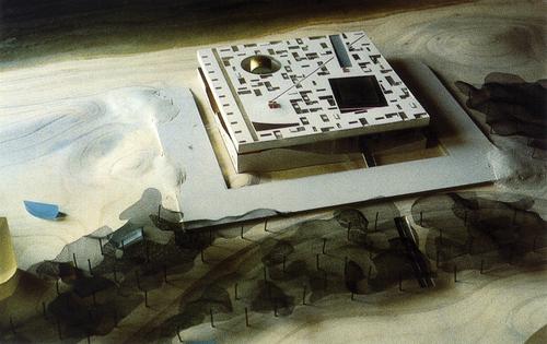
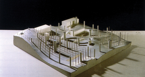
According to Koolhaas, the building’s concept is based on “a single block sliced horizontally in two parts” (p. 382), whereby “the irregular plane of the cut is exposed by separating the two halves, creating an enormous covered plaza on the beach” (p. 382) where the prior mentioned axes go through (). The building’s upper part, according to the author, contains a hotel, which consists of several apartments. It is also said that each of them has a private patio. In contrast, the building’s lower part contains various programs of the convention center (e.g. conference rooms, auditoriums, etc.), which “form artificial dunes, a seamless continuation of the surroundings” (p. 382). As further described, “a similar relief [to the dunes] floats on the ceiling of the portico” (p. 382), which is directly underneath the hotel. In this relief, Koolhaas mentions that there are various special programs (e.g., a nightclub and pool) and the royal chamber.
Figure 6. Bottom half of the building: visible the covered plaza with its distinctive dunes. Source: Koolhaas Citation1998a, p. 115.
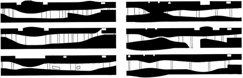
Koolhaas’ project description makes clear how important the void is for the building, especially when taking a closer look at its concept. In terms of void design strategy, four possible ways can be identified to create such a design, which are based on the interpretation of the solid and void section plans () as well as Koolhaas’ project description:
Figure 7. Section plans of the convention center. Clearly visible are its two distinctive features: the void (covered plaza), which lies in between two solids (building mass), and the solid’s wavy surface, called dunes. Source: Koolhaas Citation1998b, p. 383.
In the project description, it was mentioned that a solid (building) is cut into two halves whose surfaces are exposed by taking the halves apart. By doing so, this process creates a covered plaza in between. In this regard, it can be defined that the first strategy to create the void (covered plaza) is to make a single cut horizontally through a solid and then separate both halves (). However, from the section plans, it can be seen that the upper and lower part of the solid (building) does not fit together. This means that somehow more matter has been removed from the solid, or added, which suggests that there is another method in play. Speaking of method, this leads to the second design strategy, which is based on the first one (). Instead of just cutting once through a solid, two cuts are performed to cut out mass from the solid. This means that after the cut is performed, the solid part between both halves is removed, which creates the void. This void can then be expanded further by separating both halves from each other. As a result, the upper and lower solids have a different wavy surface, similar to the earlier shown section plans in .
Figure 8. Void design strategy 1: (A) solid block; (B) solid block with cutting line; (C) cut block with both halves separated to create a void in between; (D) final composition of solid and void. Source: graphic by author.
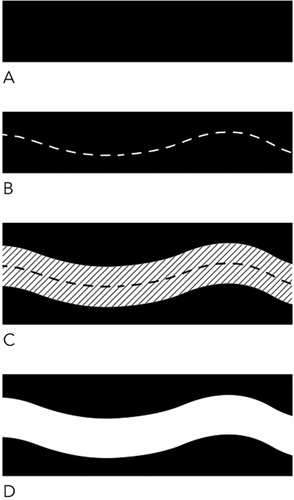
Figure 9. Void design strategy 2: (A) solid block; (B) solid block with cutting lines; (C) removal of the solid matter between the cutting lines to create an initial void; (D) separation of both halves to expand the void; (E) final composition of solid and void. Source: graphic by author.
A third strategy can be defined where first one horizontal cut – in a straight line – through a solid is performed whereby afterward, the two created halves are separated to create the void. In a next step, when the cut’s surfaces from both halves have been exposed through their separation, more matter is removed either by the method of cutting or excavating to expand the void (). Lastly, the fourth strategy, which is based on the third one, uses only the excavation method to remove matter without performing a cut. In this case, the matter that is taken away from the solid is solely removed by digging into it, which subsequently leads to the separation of a single solid into two solids and the creation of a void in between. This void can then be expanded, for example, by further separating both halves from each other ().
Figure 10. Void design strategy 3: (A) solid block; (B) solid block with cutting line; (C) cut block with both halves separated to create an initial void in between; (D) solid halves with excavation/cutting line and void in between; (E) excavation/cutting matter from the solid to expand the void; (F) final composition of solid and void. Source: graphic by author.
Figure 11. Void design strategy 4: (A) solid block; (B) solid block with excavation lines; (C) excavation of matter from the solid block to create a void; (D) continuous excavation to create two solid halves with a void in between; (E) separation of both halves to expand the void; (F) final composition of solid and void. Source: graphic by author.
Considering Koolhaas’ description and the section plans, the third void design strategy matches the most with the plans and the author’s description. However, strategy two and four basically lead to the same result, whereby it can be said that strategy four is probably the most simple one that creates Koolhaas’ design, although this method does not exactly match with his description. Coming back to strategy two, from the two techniques (cutting and excavating) that were presented in the strategy, it can be said that the excavation method is the primary void generation method, which is responsible for creating the project’s distinctive wavy surface which Koolhaas also described as dunes. Therefore, the pursued void design strategy at the convention center can be defined as the excavation of matter from a solid to generate a void.
Speaking of excavation and void, the TGB from Koolhaas is another project which makes use of the excavation technique to create void. In S,M,L,XL, by Koolhaas (Citation1998b, 602–661), the TGB is entitled “Strategy of the Void.” Characteristic for the design, as mentioned by Koolhaas, is that the library is regarded “as a solid block of information” (p. 616) with voids that are “carved out of the information solid” (p. 616). Furthermore, regarding the reading rooms, he mentions: “The TGB is a cube. It is solid storage with the reading rooms – voids—excavated where efficient” (p. 628). In addition to this, in Content, by Koolhaas, McGetrick, and OMA-AMO (Citation2004, 77), the TGB is termed as “Strategy of the Void II” (cf. Section 2.2.2. for patent), which uses the “method for defining a building through manipulating absences of building” (p. 77). Moreover, its design approach to create spaces is described as “scooping out forms from a solid block, like ice-cream” (p. 77).
From the description above, it becomes clear that the convention center and the TGB’s void design approaches are very similar, which can best be defined as the excavation of solid mass to create voids. However, while both projects use the same design strategy to create voids, the application of the design strategy slightly differs:
At the convention center, like mentioned before, a solid mass is first cut into two halves, whereby afterward both halves are separated. As a result, a continuous void is created in between. Subsequently, this void is expanded by the use of the excavation technique, which removes matter from the surfaces that were created by the cut – rather superficially and not very deep. In contrast, at the TGB, the excavation technique is applied onto a solid to either remove matter by digging, from the outside, deep into it, or to directly excavate matter from the inside. As a result, multiple, discontinuous voids are generated – some of them are connected and some are completely isolated. Thus, the difference in application of the design strategy can be defined in terms of excavation depth and location. This means that at the convention center, solid matter is removed rather superficially from the outside while the at the TGB, matter is removed more deeply by digging from the outside deep into the solid or by directly removing matter inside the solid itself.
3.3. 2 Bibliothèques Jussieu
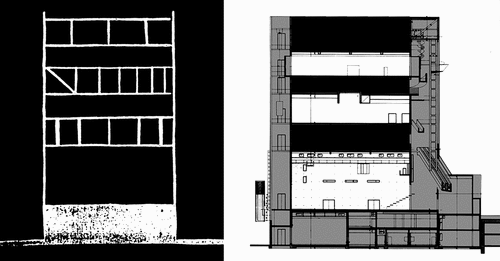
According to Koolhaas (Citation1998b, 1303–1344), the project 2 Bibliothèques Jussieu is a competition design from 1993, which was done in Paris, France. The author states that the aim of the project was to insert a new core at the Jussieu University campus, as well as “resuscitate the significance of Albert’s original project” (p. 1307). He further mentions the flaws of Albert’s project, in particular the parvis, which he describes “as residue, a mere slice of void sandwiched between socle and building” (p. 1309), which was originally intended to function as a social space. Besides the parvis being “windy, cold, empty” (p. 1308), Koolhaas also mentions that it does not work because “Jussieu is a three-dimensional network, not a building” (p. 1308). Hence, the design strategy for the project that Koolhaas pursued was as follows: “to reassert its credibility [parvis], we imagine its surface as pliable, a social magic carpet; we fold it to generate density, then form a ‘stacking’ of platforms; minimal enclosure makes it a building – the culmination of the Jussieu network” (pp. 1310–1312; ). It is said that this has led to the generation of concentration by using the same substance. Next, Koolhaas talks more about the libraries itself, which are both superimposed with the science library on the lower, and the humanity library on the higher levels. In addition to this, he refers to the parvis between the libraries, which runs from outside into the complex and functions as the so-called “accueil” (p. 1316). He further describes the parvis’ surfaces as “a vertical, intensified landscape” (p. 1316), which are “‘urbanized’: the specific elements of the libraries are reimplanted in the new public realm like buildings in a city” (pp. 1316–1317).
Figure 12. Koolhaas’ usage of Albert’s parvis as a conceptual idea for the building. Source: Koolhaas Citation1996, 126–127.
As further mentioned by Koolhaas, characteristic for the building is that “sections of each level are manipulated to touch those above and below” (pp. 1318–1321), which leads to that “all the planes are connected by a single trajectory, a warped interior boulevard [basically the parvis] that exposes and relates all programmatic elements” (p. 1320–1323; ). In addition, it said that the planes function almost like a street, which create “a system of supra-programmatic ‘urban’ elements in the interior: plazas, parks, monumental staircases, cafés, shops” (p. 1326). Lastly, Koolhaas expands on the durability of the settlements (program) and the building’s structure, which he compares to the city. He describes that the public domain and the path are durable like the city, whereby the infills (library elements) are comparable to individual architectures, from which he concludes that “in this structure, program can change continuously, without affecting architectural character” (p. 1329; ).
Figure 13. Model photo of the library (left) and diagram of the interior boulevard (right) that runs through the entire building. Source: Koolhaas Citation1996, 141 (left); Koolhaas Citation1998b, 1312 (right).
Figure 14. Second, third, and fourth floor (from left to right). Clearly visible, the internal boulevard (path) indicated with arrows, which is surrounded by the library elements (program). Source: Koolhaas Citation1996, p. 137.
The project at Jussieu illustrates an interesting design approach, which essentially uses void as the main design element. As described by Koolhaas, the library’s concept is based on Albert’s parvis, which is used conceptually as a pliable carpet. By folding the parvis in conjunction with the mentioned stacking of platforms, which are generated from the parvis, the building is finally created. At this point, the void comes into play: Koolhaas has described the parvis as a “slice of void,” which he, as described above, has used as a basis to create the building. This concept essentially leads to a building which, as a whole, can be considered as a void in itself in the urban setting of the Jussieu Campus, which fills the vacancy of the original parvis’ malfunction as a social space. Nonetheless, inside the building, there is a specific element that causes the building to function like this and therefore can be considered as the “true” void element in the project, which is namely the trajectory – an important element of the building that Koolhaas described as a boulevard which connects all the program.
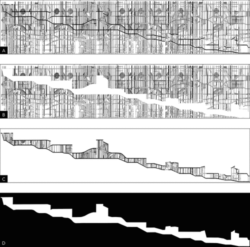
As mentioned by Koolhaas, the trajectory connects the individual floors together, which means that this element basically functions as the core of the building. By taking a closer look at the plans, in particular the “rotated-section” which is an assembly of multiple sections throughout the entire building that form together one continuous section, the extent and importance of the core becomes visible (). From the plan, it can be seen that the core is one continuous element, which starts at the bottom of the building and ends at the top of it. By isolating the core, this phenomenon becomes even more obvious (). Furthermore, the isolation makes the core’s variability in height and incline clearly visible, which is basically responsible for creating multiple scenarios and atmospheres for the visitors walking on this path, or as Koolhaas describes it: “The visitor becomes a Baudelairean flâneur, inspecting and being seduced by a world of books and information – by the urban scenario” (pp. 1322–1325). In essence, this shows that the core can be regarded as the true void element in the building, which functions as the condensed concept (parvis). In contrast to this void element, the rest of the building can be regarded as the solid ().
Figure 15. Analysis of the rotated-section: (A) original assembled section; (B) extraction of the boulevard; (C) isolated boulevard; (D) solid and void diagram of the section. Source: Koolhaas Citation1996, 140–141 (A); graphics by author on the basis of a (B – D).
Besides the core, there is another element that can be regarded as the void, which Koolhaas brought up when he talked about the durability of the building: the library elements. He mentioned that the public domain and the path (core) are durable like the city, which stand in contrast to the library elements that resemble individual architectures. To this, he added that the building’s program can change. This statement of Koolhaas basically implies that the program in itself can be regarded as a type of void element that is implanted into the building and used as a void design element due to its possibility to change – similar to the genetic modification approach, where the program basically functions as the void (cf. Section 2.2.1.).
Overall, the analysis has shown that the core can primarily be seen as the void element in this project, which is a crucial part of the building due to its function (circulation) to fill the building with life. Regarding the void design approach to create such a concept, Koolhaas’ used technique to create the void at the library, as suggests, can be defined as cutting through a solid. This means that the building volume is embodied as the solid and the core as the void (circulation) that gets generated by a cut through the solid.
A similar void design approach of cutting through a solid to generate voids can be seen from another project of Koolhaas, namely the McCormick Tribune Campus Center at the Illinois Institute of Technology. The project, according to Koolhaas (Citation2006, 336–377), consists of a “dense mosaic” of programmatic elements where the student’s existing paths, which lead from one side of the campus to the other, “are organized through the Campus Center, to differentiate the multiplicity of activities into streets, plazas and urban islands” (p. 338).
In terms of void design approach, it can be said that the campus center makes use of the cutting method which can clearly be seen from the floor plan, especially when looking at it from the perspective of solid and void (). By looking at the plan, several lines of various thicknesses can be noticed which run through a mass, evoking the perception of cutting it apart. In this case, the lines (paths) function as the voids, whereas the mass (building) functions as the solid. Said observations support the fact that the pursued design approach to generate the paths (voids) at the campus center can be defined as the cutting method, which is used to cut through the building (solid) to generate the paths (voids). As it can be seen, said approach is similar to the prior presented project 2 Bibliothèques Jussieu, where the cut through the building (solid) generated the core (void).
Figure 16. Solid and void plan of the campus center with “void-lines” (paths) that run through a solid mass (building), evoking to cut it apart. Source: Koolhaas Citation2006, 339 (edited by author).
Lastly, there is one key difference to mention between the two projects, which is the field of application in plan where the cutting method is used. In the project 2 Bibliothèques Jussieu, the cut is performed in the section, whereas at the campus center, the cut is performed in the floor plan. Nonetheless, the created void functions similarly in both projects, namely as a circulation element that fills the building with life. This means, that the cutting method is not solely bound to the floor plan or the section, but rather can be applied in either plan to achieve the same result.
3.4. Seattle Central Library
According to Koolhaas (Citation2007, 62–117), the project Seattle Central Library is located in Washington (USA) and was built from 1999 to 2004. As mentioned by the author, the building consists of so-called programmatic clusters, which are divided into five stability clusters and four instability clusters (). Characteristic for the building, as described, are its platforms – each is one of the five programmatic clusters – and the spaces between them (). As further mentioned, the “size, flexibility, circulation, palette, structure, and MEP” (p. 72) of each platform is different, so each can fulfill a distinctive function. Moreover, it is said that “the spaces in between the platforms function as trading floors” (p. 72), which are used “for work, interaction, and play” (p. 72). In short, Koolhaas describes the concept of the Seattle Central Library as “genetically modifying the superposition of floors in the typical American high rise” (p. 72), which leads to that the building is simultaneously iconic, contextual (different reaction of each side to its surroundings), and sensitive (form allows high amounts of daylight or gives shade).
Figure 17. Programmatic clusters: five stability clusters (left) and the four instability clusters between them (right).Source: Koolhaas Citation2007, p. 72.
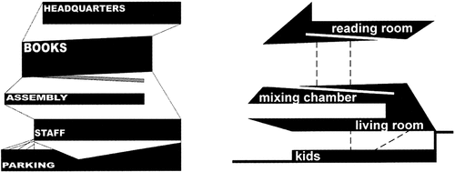
Figure 18. Model of the Seattle Central Library with the visible platforms, the so-called stability clusters, and the spaces between them, the so-called instability clusters.Source: Koolhaas Citation2007, p. 72.
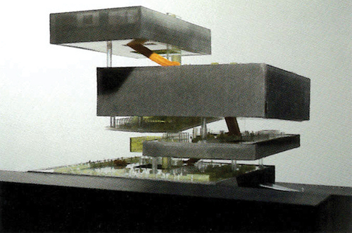
The library’s concept is probably the most important part of the project, which is responsible for its unique organization. Interesting is that the concept is essentially based on a solid and void design approach, which can directly be seen from the concept plans in . By taking a closer look at these plans, the prior mentioned five stability clusters (platforms) can be seen as the solid elements, whereas the remaining four instability clusters between them can be seen as the voids. In this regard, the design strategy to create the building concept can be described as the alternating superposition of the programmatic stability clusters (solids) with the programmatic instability clusters (voids) on top of each other. This leads to that the pursued void design strategy at the Seattle Central Library can be defined as the alternating superposition of solids and voids on top of each other to create a contrast with the voids.
Another project from Koolhaas that uses a similar void design approach is the ZKM. According to Koolhaas (Citation1998b, 686–761), the ZKM is located in Karlsruhe (Germany) and was built between 1989 and 1992. Characteristic for the building is, as mentioned by the author, that all the program is located in a single container which consists of various facilities, such as a contemporary art museum, a media art museum, a media library, a lecture hall, etc. As further described, the strategy to incorporate all program in a single container was to create different circumstances, such as provoking tension, generating density, organizing in-betweens, and so on.
Characteristic for the inside, as described by Koolhaas, is the superimposition of the program in a so-called “single stack” – essentially the building’s core – which is structured in a sequence that “corresponds to a transition from production/research to display, from artificial to ‘natural,’ from private to public” (p. 695). In addition to this, he mentions the characteristic building structure, which consists of seven vierendeel beams, each with a depth of six meters, that span between the core’s walls (from east to west). It is further said that these are “creating an alternation between floors completely free of structure … and floors of inhabited structure that are ‘marked’ by the different vierendeels, which oscillate between structural support and architectural definer, utility and aesthetics, necessity and decor” (p. 695). As a last characteristic, Koolhaas mentions that the core – he also calls it “deep core” – is enclosed by four zones, which all exhibit a different function.
At the ZKM, the pursued strategy of superposition seems not as obvious as in the previous project of the Seattle Central Library. However, to reveal the design strategy, the solid and void elements have to be defined first, which are basically the floors that contain vierendeel beams (solids) and the floors that do not contain vierendeel beams (voids). This definition of solid and void elements is not only based on Koolhaas’ project description, but also supported in the writing called “Last Apples” in S,M,L,XL, by Koolhaas (Citation1998b, 662–685), where it is described that “the vierendeels, either through their absence or their presence, become the major instruments that characterize the interior” (p. 675). The statement basically implies that the vierendeels create a contrast in the interior based on their existence (presence vs. absence), similar to what Koolhaas mentioned in his project description (). Thus, said contrast can be linked to solid and void, like mentioned above, with the solid elements as the floors where the vierendeel beams are present, and the void elements where the vierendeel beams are absent. In this regard, it can be said that the void design strategy of superposition at ZKM is basically the alternate piling of floors with and without vierendeel beams.
Figure 19. Solid and void elements at the ZKM: structural concept from Koolhaas’ writing “last apples” (left) and an analysis of the building’s section plan with indicated solid (black) and void (white) elements (right). Source: Koolhaas Citation1998b, 675 (left); Koolhaas Citation1998c, 89 (right; edited by author).
Overall, the void design strategy of superposition is in both projects very similar, namely the alternate piling of solids and voids on top of each other. In addition to this, said strategy is in both projects connected to the building’s floors, which are used as the solid and void elements. However, the elements that define the floors as solids and voids are different. At the Seattle Central Library, the program (stability vs. instability) was essentially the defining element that characterizes the floors as solids and voids, whereas at the ZKM, the vierendeel structure (presence vs. absence) was the defining element. Thus, the void design strategy of superposition can be summarized as the creation of a contrast, which can manifest itself very differently like, for example, as contrasting programs (stability vs. instability), or a different load bearing structure that shapes the interior (presence vs. absence).
4. Synthesis
This section synthesizes the gathered information from the project analysis in three main parts. In the first part, a genealogy for the SotV is presented, which is structured in three different tiers. Objects that are included in the genealogy are Koolhaas’ original SotV I+II, two inspirational projects, and four new void design strategies. Afterward, part two and part three will take a closer look at the four new void design strategies, with each of them presenting two strategies based on their categorization in the genealogy.
4.1. The genealogy of the strategy of the void
During the various analyses, it became clear that Koolhaas’ SotV I+II have to be based on some kind of idea that dates back prior to their establishment. This discovery was particularly reinforced during the project analysis, where two of the projects have shown that their used void design method – in connection with other theories – actually has a strong relationship to Koolhaas’ first SotV, which means that their design strategy can basically be seen as a predecessor to Koolhaas’ strategy.
In this light, the hypothesis is made that the inspiration and initial idea for the SotV I+II dates back long before their actual establishment, meaning that they originate from some of Koolhaas’ earlier projects and observations which he made as an architect and student. Under this premise, a genealogy for the SotV was created, which can be seen in .
Figure 20. Genealogy of the strategy of the void, which is structured in three different tiers. Source: graphic by author.
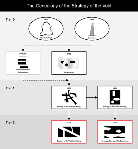
The genealogy shows in which observations Koolhaas probably found inspiration to develop prototype projects (cf. Section 4.2.1.) that deal with the topic of void design, and which of these may have served him as a basis to develop his idea of the first SotV. Besides this, the genealogy further shows how the SotV can possibly be expanded through some additional strategies – termed as succeeding strategies – that are based on Koolhaas’ original ones (cf. Section 4.2.2.). Speaking of the succeeding strategies, the genealogy further proposes a classification scheme for these strategies, which fits them among Koolhaas’ original ones. The benefits of this classification system are that the strategies can easily be distinguished from one another and that it shows their origin, which means that it illustrates their relation to Koolhaas’ original SotV.
Lastly, the genealogy itself is based on three tiers; however, the tiers can easily be expanded, for example, to incorporate even more strategies. To get a bit more insight into this system, the individual tiers are subsequently presented in more detail, which are followed by the presentation of the classification system for the succeeding strategies.
4.1.1. The original strategies: tier 1
The starting point for the genealogy marks the first SotV (cf. Section 2.2.2. for patent), which is based on the project Melun-Sénart (1987) and its void concept of bands (Koolhaas Citation1998b, 972–989). The second SotV, which is based on the TGB (1989), is of course related to the first one and therefore can be seen as a successor of it. In the genealogical tree, these two strategies are defined as Tier 1.
4.1.2. The predecessors: tier 0
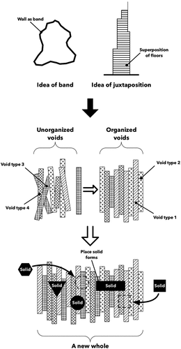
This tier includes two observations, the Berlin Wall and the skyscraper, and two prototype void design strategies, “SotV: Juxtaposition” and “SotV: Superposition,” that deal with similar topics as the first SotV in tier 1 and thus are defined as their predecessors. In this regard, the two strategies can be seen as preceding approaches to Koolhaa’s original SotV, while the observations are seen as the initial ideas on which they are based.
One of the strategies that can be seen as a predecessor to the first SotV is based on the Parc de la Villette (1982) whose void design method of juxtaposition is also related to the concept of the band like Melun-Sénart. In this regard, it can be hypothesized that the idea for the Parc de la Villette’s concept of juxtaposing bands is based on two earlier projects that Koolhaas has encountered, namely the Berlin Wall and the skyscraper. This means that the idea of the band actually stems from the Berlin Wall, which can basically be seen as a type of band or, according to Thuer and Nam’s (Citation2023) research, as a one-dimensional line void. Moreover, it can be said that the idea of juxtaposition stems from the skyscraper which uses a similar concept, namely the superposition of floors in the section – when rotating the section 90 degrees it is like a juxtaposition. Finally, their combination – the juxtaposition of bands (voids) in the floor plan – essentially describes the underlying concept of the Parc de la Villette, and therefore it can be said that both phenomena (projects) served Koolhaas as an inspirational source for la Villette.
Moreover, the void design strategy that is deployed at the Seattle Central Library (1999–2004) can also be seen as a kind of predecessor to the first SotV. Although being built much later, it can be said that the project essentially uses the same idea of the Berlin Wall (band) and the skyscraper (superposition) to superpose bands (voids and solids) in the section as a design method. This phenomenon can further be seen from Lucan’s (Lucan Citation2012) statement that was earlier mentioned, where he describes that the library is “‘genetically modifying the superposition of floors in the typical American high-rise’” (as cited in Lucan, p. 559), resulting in that “one level never exactly superposed on the other” (p. 559). In this regard, the library can be defined as a type of predecessor to the first SotV; however, not a direct one, because it is built later, but an indirect one due to dealing with similar topics (band and superposition).
4.1.3. The successors: tier 2
Tier 2, the successor to the original SotV in Tier 1, consists of two succeeding void design strategies, which are called “SotV 2.0: Cutting” and “SotV 2.0: Excavating.” Due to their specific relation to one of the original strategies, the SotV 2.0: Cutting is classified as a direct successor to the SotV I whereas the SotV 2.0: Excavating is classified as a direct successor to the SotV II. In this regard, the original SotV function as so-called parent strategies to the succeeding ones that function as their children.
4.1.4. Classification scheme for the succeeding void design strategies
As initially mentioned, the genealogy proposes a classification scheme for the succeeding strategies, which is based on the original SotV’s system. In particular, the new system uses the original strategies’ roman numbering system and adds letters to it. By doing so, it is possible to directly see the relation between the succeeding strategies and the original ones. For example, the SotV 2.0: Cutting is classified as “I.A.” This means, the roman number “I” indicates that this strategy is a direct successor of the original SotV I whereas the letter “A” indicates that this strategy is the first succeeding one in this tier. If there would be a second strategy that is related to the first SotV, it would be termed as “I.B.” In case a succeeding strategy would be created that is not related to one of the original strategies, said strategy would form a new parent in Tier 2, and it would be named just as “A” without a roman number.
As seen, the classification system is very flexible, which means that its flexibility not only allows the system to incorporate more void design strategies into it but also allows it, at the same time, to create and maintain a coherent whole. In this regard, the system, in combination with the genealogy, basically lays ground for a design theory about void design – the beginning of a void design compendium – on which can be built upon. Furthermore, it shows practically how it is possible to continue Koolhaas’ original SotV.
4.2. Strategy of the void: predecessors and successors
This section presents four different void design strategies from the prior shown genealogy. In particular, two preceding strategies (Tier 0) and two succeeding strategies (Tier 2) are presented, which are called (1) juxtaposition and (2) superposition, and (3) cutting and (4) excavating, respectively.
The presentation of the strategies is supplemented by several drawings. These drawings graphically illustrate the synthesized information which were gathered from the various analyses. Specifically, this means that all four strategies include information that are divided into two parts: (1) design approach and (2) characteristics. The first part includes information about the name of the used design action and its outcome. The second part includes information about its field of application (e.g. one-, two-, or three-dimensional), its application in plan (e.g. section, floor plan, elevation, etc.), and some more specific information that are different for each strategy. In addition, the two preceding strategies include further information concerning the impact of their inspirational sources onto their void design approach.
All this information is finally condensed into four void design patents in Appendices A to D – similar to the ones from Koolhaas – that make it possible to see at one glance the specific characteristics of the strategies and how they work. As a result, potential designers that want to use these strategies can easily refer to these patents for their design purposes, meaning they function as a kind of design assistance. Or, if someone wants to learn more about the history of the SotV I+II, they can specifically refer to the preceding patents. However, all four strategies must be seen as a further development of Koolhaas’ SotV, which means that they are more detailed than Koolhaas’ original ones, making them precisely usable in specific scenarios based on someone’s design intent.
Speaking of design, the strategies must be regarded as so-called universal strategies, which means that they do not only create the analyzed designs, but rather create completely new ones – they are only based on the analyzed projects and their void design approach. This further means that the strategies should also be used, as mentioned at the beginning of this article, in other areas, such as urban design, to make use of the void’s special design features.
Lastly, the strategies’ naming scheme is based on the specific void design action (verb) that each of them uses. This makes them not only clearly distinguishable from one another but also directly tells the strategies’ intended design purpose. Thus, the scheme makes it easy and intuitive to choose one strategy. However, to distinguish between the preceding and succeeding strategies, their naming schemes slightly differ – like their patents. In particular, this means that the former uses the void design action in the infinitive verb form, while the latter uses the gerund.
4.2.1. The predecessors
4.2.1.1. Juxtaposition [prototype]
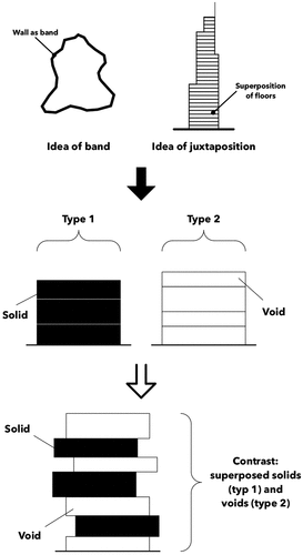
The first preceding void design strategy – see Appendix A for patent – is primarily based on the project Parc de la Villette, but also its inspiring projects the Berlin Wall (idea of band) and the skyscraper (idea of juxtaposition). In addition, its successor Melun-Sénart, the first SotV, functions also as a kind of basis for it. The void design method with which this strategy is dealing revolves around the juxtaposition of voids (bands). This design technique was essentially used at la Villette, and to some extent at Melun-Sénart, in order to create a completely new whole that works as some kind of underlying concept (hypothesis) – the primary goal of this technique ().
Figure 21. From the Berlin Wall and the skyscraper to the void design method of juxtaposition, which juxtaposes voids to create a completely new whole (concept). Source: graphic by author.
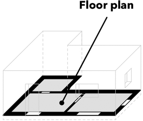
Characteristic at la Villette, as at Melun-Sénart, was that the juxtaposition of the voids was performed in the floor plan, which therefore can be defined as the method’s field of application in plan (). This further means that the technique can also be defined as being bound to a two-dimensional (2D) space that lies, in relation to a coordinate system, on the XZ axis (). In addition, the juxtaposed voids at la Villette have similar shapes but completely different sizes; in particular, they have the same width but a different length. Therefore, the shape and size of the voids for the juxtaposition can be defined as being “variable” (see example voids in ). The same phenomenon shows its direct successor Melun-Sénart whose voids are also different, but not only in size but also in shape.
Figure 22. Void creation method 1: subdivision. Source: graphic by author.
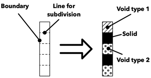
Figure 23. Void creation method 2: deduction. Source: graphic by author.
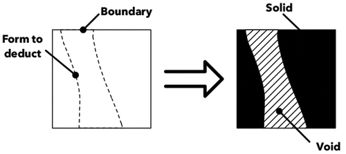
Speaking of void creation, the voids at la Villette were basically created by subdividing the site (), whereas the voids at Melun-Sénart were created through deduction (). This means that the number of generated voids through these creation processes can vastly differ. Hence, the number of voids that are needed to use the strategy of juxtaposition can be defined as being “variable;” however, there is actually a minimum amount of voids required to perform the technique, which is two ().
Figure 24. Minimum amount of voids to perform the design method. Source: graphic by author.
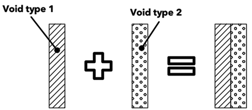
Figure 25. The design method’s field of application is two-dimensional and lies on the XZ axis. Source: graphic by author.
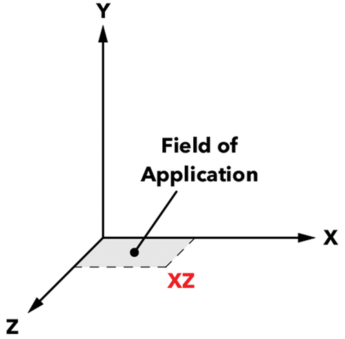
Figure 26. The design method’s field of application in plan is bound to the floor plan. Source: graphic by author.
4.2.1.2. Superposition [prototype]
The second, indirect, preceding void design strategy – see Appendix B for patent – is primarily based on the project Seattle Central Library and its inspiring projects the Berlin Wall (idea of band) and the skyscraper (idea of superposition), but also to some degree on the ZKM. The void design method with which this strategy is dealing revolves around the superposition of voids (and solids). This design technique was essentially used at the library and the ZKM to alternately superpose voids and solids on top of each other, which leads to the creation of a contrast between the two elements ().
Figure 27. From the Berlin Wall and the skyscraper to the void design method of superposition, which alternately superposes voids and solids to create a contrast. Source: graphic by author.
Characteristic for the library and the ZKM was that both of them have used this method in the section, which means that its primary field of application in plan can be defined as being in the section. However, the technique can hypothetically also be used in elevation and in a 3D space (e.g., a 3D-model) due to the similar functionality of the technique in these two perspectives as in the section (). In this regard, the method’s field of application can be defined as being either bound to a 2D or 3D space that lies, in relation to a coordinate system, on the XY, YZ, or XYZ axis ().
Figure 28. Types of contrasts (examples): different load bearing structure, room height, and lighting (from left to right). Source: graphic by author.
Figure 29. Type of superposition and shape of the voids and solids (based on Figure 28): the alternating superposition of voids and solids that can adopt various shapes based on their used contrast. Source: graphic by author.
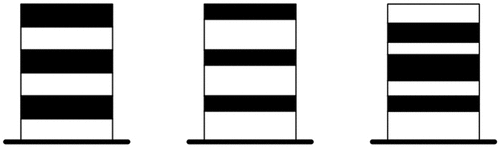
The projects further show that the type of contrast that the superposition generates can be embodied in multiple ways, such as the load bearing structure, program, atmosphere, room height, or lighting – in other words, in various architectural concepts (). Thus, the type of contrast that the technique of superposition generates varies. Speaking of contrast types, the projects further show that the shape of the voids, and solids, in which the contrasts are embodied have basically no fixed form, which means that their shape can be defined as being “variable.” Lastly, to create a contrast (e.g., one of the previous mentioned), the superposition of the voids and solids has to be, as initially mentioned, alternating, which basically describes the type of superposition that this method uses ().
Figure 30. The design method’s field of application is two- and three-dimensional and lies on the XY, YZ, or XYZ axis Source: graphic by author.
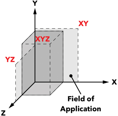
Figure 31. The design method’s field of application in plan is bound to the section, elevation, and 3D-model. Source: graphic by author.
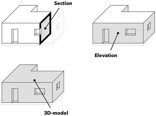
4.2.2. The successors
4.2.2.1. Cutting
The third void design strategy – see Appendix C for patent – is based on the projects 2 Bibliothèques Jussieu and the McCormick Tribune Campus Center at the Illinois Institute of Technology. The void design method with which this strategy is dealing revolves around the action of cutting, through a solid, to generate voids. This design technique was essentially used in both projects to create a circulation space, which means that the primary goal of this technique can be defined as the establishment of a network ().
Figure 32. The establishment of a network (circulation): the cut through a solid creates a void that functions as a connective element. Source: graphic by author.
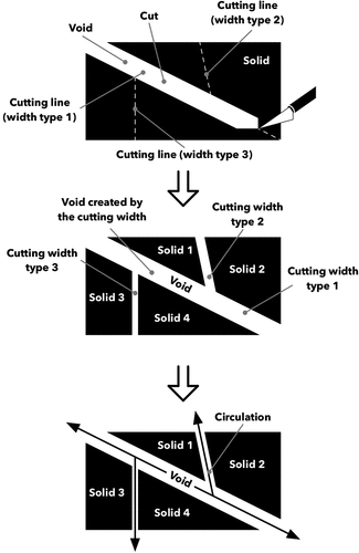
Characteristic for both projects was that they have used the design method either in section or floor plan, which basically describes the method’s field of application in plan (). This further means that its field of application can be defined as being limited to a 2D space that lies, in relation to a coordinate system, on the XY, YZ, or XZ axis (). By taking a closer look at the cut itself and how it was performed, it can be identified that in the projects the cut was performed, more or less, in a straight line. This means that the path can be defined as being linear. Regarding the cutting line’s width, both projects have shown that the line’s width can greatly differ, meaning that the cutting line can adopt multiple thicknesses (). For example, when the cutting line is applied onto a solid to cut it, the line can have a thickness that ranges from thin, which does not erase a lot of matter, to thick, which erases a substantial amount of matter. This illustrates that the dimensions of the void is dependent on the cutting width ().
Figure 33. Path type with example widths: linear path that can adopt different widths. Source: graphic by author.
Figure 34. Dimensions of the void: the cutting line’s width correlates with the width of the created void. Source: graphic by author.
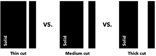
Figure 35. The design method’s field of application is two-dimensional and lies on the XY, YZ, or XZ axis. Source: graphic by author.
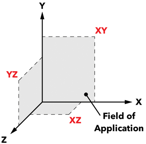
Figure 36. The design method’s field of application in plan is bound to the floor plan and section. Source: graphic by author.
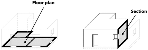
4.2.2.2. Excavating
The fourth, and last, void design strategy – see Appendix D for patent – is based on the projects Palm Bay Seafront Hotel and Convention Center and the TGB. The void design method with which this strategy is dealing revolves around the excavation of mass, from a solid, to generate voids. This design technique was essentially used in both projects to create sheltered spaces inside a solid, whose organic shapes resemble in a way the shape of a cave. In this regard, the goal of this technique can be defined as the creation of architectural spaces through the excavation of mass from a solid form ().
Figure 37. The creation of architectural spaces: the excavation of mass from a solid creates a void that functions as an architectural space. Source: graphic by author.
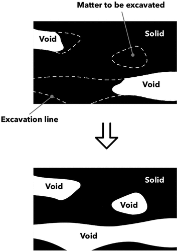
Both projects have applied this design method in section, floor plan, or a combination of both, which means that it can be defined that the design technique can be applied in section and floor plan. However, it can also be said that the method can be applied in elevation due to its similarity to the section. Moreover, it must be noted that the method can not only be used in a 2D space, but also in a three-dimensional (3D) space like, for example, Koolhaas did with the physical void model at TGB (). The difference between the usage of the design technique in a 2D space compared to a 3D space is that in the former, the method creates first a 2D void that has to be translated later into a 3D void to create an actual architectural space, whereas in the latter, the method directly creates an architectural space (3D void), meaning that its application in a 2D space is rather abstract. In this regard, the method’s field of application can be defined as being bound to a 2D or 3D space that lies, in relation to a coordinate system, on the XY, YZ, XZ, or XYZ axis ().
Figure 38. Type, shape, size, and the position of excavation of the voids: continuous vs. discontinuous voids of variable shapes and sizes whose excavation can either start from outside or inside a solid mass. Source: graphic by author.
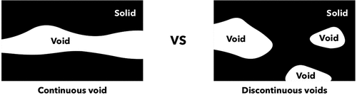
Figure 39. Types of excavation depth: deep excavation vs. superficial excavation. Source: graphic by author.
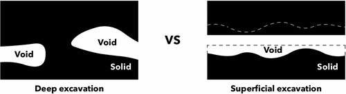
Regarding the created voids, two types of voids can be determined from the projects: continuous and discontinuous voids. Moreover, it can be identified that the dimension of these voids varies greatly, which means that their shape can range from geometric to organic with sizes that range from small to large. Thus, the shape and size of the voids created through this method can be defined as being “variable.” Besides this, two positions can be identified from the projects where the excavation process is started: first, by removing mass from outside the solid, and second, by removing mass directly from the inside of the solid. Therefore, it can be defined that the starting position of the excavation can either be from outside or inside a solid mass (). Lastly, the projects illustrate that the excavation depth can also differ (). This means that the excavation depth can be defined as being either superficial, like at the convention center, or more deep, like at the TGB.
Figure 40. The design method’s field of application is two- and three-dimensional and lies on the XY, YZ, XZ, or XYZ axis. Source: graphic by author.
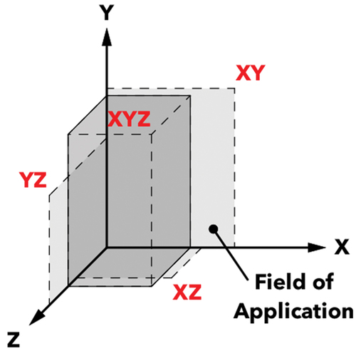
Figure 41. The design method’s field of application in plan is bound to the floor plan, section, elevation, and 3D-model. Source: graphic by author.
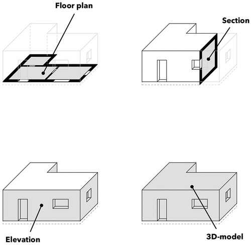
5. Conclusion
The goal of this research was to take a closer look at the topic of void design; in particular, its potential as a design tool. This was done by proposing some novel void design strategies on the basis of Koolhaas’ original SotV I+II. As a result, four design strategies have emerged-two preceding and two succeeding strategies to Koolhaas’ SotV I+II – including a genealogy that hypothesizes the history and future of the SotV, which basically lays the groundwork for the creation of a larger theoretical work about void design that continues Koolhaas’ original SotV I+II. Moreover, the study has shown through the various project and theory analyses how Koolhaas’ perceives void and how he uses the void as a design technique. As a result, it can be said that both his perception of the void and his usage of it as a design technique are extremely diverse.
The project analysis and the subsequent created void design strategies (patents) have specifically revealed that the void can be used as an extremely flexible design element and that it is possible with them to create a multitude of diverse architectural designs – even on different scales (e.g., buildings or urban designs). For example, the method of cutting could be used, like Koolhaas did at the McCormick Tribune Campus Center, to create a circulation space in a building for the users; however, on a larger scale, such as during the massing phase in urban design, the method could be used to create circulation spaces for pedestrians and vehicles. Speaking of urban design, the method also has the potential to propose solutions for urban development. This means, for example, that an area can be regarded as a solid form, and by cutting through it, an infrastructure network (circulation for pedestrians and vehicles) can be generated. The leftover parts in between the network function in this case as “building masses” on which the cutting method can be used again, but this time to generate different building typologies. These specific examples of the cutting method show, what potential the different void design strategies can have in architecture and how versatile they can be used as a tool to create unique architectures and design solutions.
Speaking of the design methods’ versatility, future research about the void design methods could specifically target their different use cases and show, for example, through some real-world projects, how these methods could be applied to generate said unique architectures and design solutions. Moreover, future research could also analyze other projects from Koolhaas – or from other architects to get a more diverse view on the topic of void design – to uncover more void design strategies, expand this theory, and get an even better understanding of Koolhaas’ specific use of void in architecture as well as the use of void in general.
Lastly, the limitations of this research primarily concerns two things. First, the study is limited to one architect. Second, the number of projects that were used for the analysis is limited to two for each design strategy (one primary and one secondary project). The reason to focus on just one architect was to thoroughly analyze and examine the architect’s specific void design approach; otherwise, the analysis of more architects in such detail would have gone far beyond the scope of the research. Speaking of the research scope, the limited amount of projects is also primarily due to its scope, which otherwise would have been far too large when analyzing more projects in such detail. However, the goal for the analysis was to always include at least one supplementary project to the main one. By doing so, it was not only possible to expand the scope to some degree, but also to get a different point of view on the analyzed information from the main project.
Disclosure statement
No potential conflict of interest was reported by the author(s).
Additional information
Funding
Notes on contributors
Jason Eugen Giovanni Thuer
Jason Eugen Giovanni Thuer is a Swiss native and currently enrolled as a PhD student at Hanyang University in Seoul, Korea. His main interest concerns the topic of solid and void in urbanism, with a particular passion for the theory and design with void to create more sustainable cities.
Sung-Taeg Nam
Sung-Taeg Nam is an Architecte DPLG, Ph.D EPFL and Associate Professor in Hanyang University (Seoul Campus). The main concerns are the various theories of the Architecture, ranging from Object design to Urbanism.
References
- Koolhaas, R. 1994. Delirious New York: A Retroactive Manifesto for Manhattan. new ed. New York: The Monacelli Press. Original work published 1978.
- Koolhaas, R. 1996. “Two Libraries for Jussieu: Paris, France, 1992 [Competition.” In OMA/Rem Koolhaas: 1992–1996, edited by R. C. Levene and F. M. Cecilia, 124–141. Vol. 79. Madrid: El Croquis editorial.
- Koolhaas, R. 1998a. “Hotel and Convention Centre in Agadir: Agadir, Morocco, 1990 [Competition].” In Vol. 53+79 OMA/Rem Koolhaas: 1987–1998, <edited by R. C. Levene and F. M. Cecilia, 102–115. omnibus. Madrid: El Croquis editorial.
- Koolhaas, R. 1998b. Small, Medium, Large, Extra-Large (OMA, Contributor; J. Sigler, Ed.; H. Werlemann, Photography; & B. Mau, Design. 2nd ed. The Monacelli Press. Original work published 1995.
- Koolhaas, R. 1998c. “ZKM [Centre for Art and Media Technologie]: Karlsruhe, Germany, 1989 [Competition, First Prize].” In Vol. 53+79 OMA/Rem Koolhaas: 1987–1998, <edited by R. C. Levene and F. M. Cecilia, 84–101. omnibus. Madrid: El Croquis editorial.
- Koolhaas, R. 2002, Spring. Junkspace. October, 100, pp. 175–190. Retrieved from https://www.jstor.org/stable/779098.
- Koolhaas, R. 2006. “The McCormick Tribune Campus Center at ITT: Chicago, Illinois, USA, 1997–2003, Competition First Prize.” In OMA/Rem Koolhaas (I): 1996–2006, edited by F. M. Cecilia and R. Levene, 336–377. Vols. 131–132. Madrid: El Croquis editorial.
- Koolhaas, R. 2007. “Seattle Central Library: Washington, USA, 1999–2004.” In OMA/Rem Koolhaas (II): 1996–2007, edited by F. M. Cecilia and R. Levene, 62–117. Vols. 134–135. Madrid: El Croquis editorial.
- Lucan, J. 2012. Composition, Non-Composition: Architecture and Theory in the Nineteenth and Twentieth Centuries. Lausanne: EPFL Press. Original work published 2009.
- OMA-AMO. 2004. Content: Perverted Architecture. Koolhaas, R., McGetrick, B., edited by. Köln: Taschen.
- Rowe, C., and F. Koetter. 1978. Collage City. Cambridge, Massachusetts: The MIT Press.
- Thuer, J. E. G., and S.-T. Nam. 2023. “The Collage of Void versus Solid: Ungers and Koolhaas—Void as a Design Element and Theory.” Journal of Asian Architecture and Building Engineering 1–29. Advance online publication. https://doi.org/10.1080/13467581.2023.2205496.
- Ungers, O. M. 1963 July. “Zum Projekt Neue Stadt in Köln [About the Project «New Town» in Cologne].” Das Werk: Architektur und Kunst 50 (7): 281–284. https://doi.org/10.5169/seals-87093.
- Ungers, O. M. (with S. Marot. 2013. “The City in the City.” In The City in the City. Berlin: A Green Archipelago—A Manifesto (1977) by Oswald Mathias Ungers and Rem Koolhaas with Peter Riemann, Hans Kollhoff, and Arthur Ovaska (S. Marot, Trans., edited by F. Hertweck and S. Marot, 71–130. Zürich: Lars Müller Publishers. Original work published 1977.
Appendix A:
Patent for Void Design
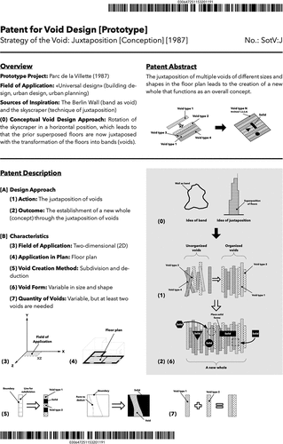
Appendix B:
Patent for Void Design
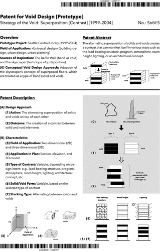
Appendix C:
Patent for Void Design
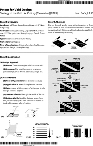
Appendix D:
Patent for Void Design