
 ?Mathematical formulae have been encoded as MathML and are displayed in this HTML version using MathJax in order to improve their display. Uncheck the box to turn MathJax off. This feature requires Javascript. Click on a formula to zoom.
ABSTRACT
To address the issue of inadequate control effect resulting from the challenge of measuring state feedback information comprehensively, this paper proposes an iterative output feedback energy-to-peak control method that solely depends on partial external observation data. This paper presents the computational steps for achieving a suboptimal solution to the output feedback bilinear matrix inequality constrained problem using an iterative linear matrix inequality approach. The proposed method overcomes the challenge of numerically solving the optimization problem. The unknown variables in the output feedback linear matrix inequality optimization problem are transformed equivalently to obtain a new linear matrix inequality optimization problem. The numerical results of the two optimization problems are then used to iterate with each other and obtain a suboptimal solution. A comprehensive analysis was conducted on an 8-story building structure, utilizing state feedback, output feedback, and iterative output feedback energy-to-peak control techniques. The results of the study indicate that the proposed iterative output feedback energy-to-peak control approach efficiently reduces the displacement and acceleration response of the structure, exhibiting superior control effectiveness than both the state feedback and output feedback energy-to-peak control methods. The findings demonstrate the practicality and versatility of the suggested method.
1. Introduction
In the field of civil engineering, the development and application of high-rise building structures (Wang et al. Citation2019; Wang, Shi, and Zhou Citation2019; Wang, Zhou, and Shi Citation2023b) are becoming increasingly common in cities. Therefore, continuous research is needed for the vibration control technology of these structures. There are now many technical devices available for vibration control, and research related to tuned mass dampers (Wang et al. Citation2020, Citation2020; Wang, Shi, and Zhou Citation2022) is particularly popular. These studies primarily focus on combining active control techniques with the passive control technique of tuned mass dampers for various applications (Wang et al. Citation2022, Citation2023; Wang, Zhou, and Shi Citation2023a).
Active control strategies (Li, Chen, and Teng Citation2019; Li et al. Citation2019; Xu et al. Citation2022) for building structures have been the focus of significant attention due to their ability to achieve effective control. State feedback methods (Al-Fahdawi and Barroso Citation2021; Chen et al. Citation2021; Saeed, Sun, and Elias Citation2022) are preferred by most researchers in designing active controllers, as they have demonstrated to be more efficient in improving system performance. However, the comprehensive measurement of state feedback information in practical applications can often prove challenging, rendering state feedback control systems technically difficult and expensive to implement. As a result, output feedback control strategies (Yang, Li, and Qiu Citation2019) that rely solely on externally measurable signals have emerged as a notable research pursuit.
In the field of automatic control, researchers have conducted extensive and profound research on output feedback strategy (Chandiramani Citation2016; Hao and Duan Citation2017; Kazemy, Zhang, and Han Citation2017; Lan et al. Citation2020; Rahmani, Ziaiefar, and Hashemi Citation2022), with particular emphasis on the challenging task of solving control problems. In the early stages, the main method utilized was the Riccati equation. However, this approach had some limitations as it required predetermined parameter settings which tended to lead to conservative analytical outcomes. As the interior point method emerged for solving convex optimization difficulties, and many control problems could be transformed into linear matrix inequality optimization or feasibility problems, it became convenient and efficient to solve output feedback control problems. Subsequently, researchers began applying the linear matrix inequality method extensively to address output feedback problems (Kazemy, Gyurkovics, and Takács Citation2020; Palacios-Quiñonero et al. Citation2017). The primary focus of the literature discussed above is to determine the solution of the output feedback gain matrix. Specifically, researchers aim to identify the feasible solution for the existence of the linear matrix inequality. Various methods have been proposed, including linearized convex-concave decomposition, alternating projection method, and resilient approach (Sadabadi and Peaucelle Citation2016). Among these methods, the variable transformation approach is the most straightforward to apply (Rubió-Massegú et al. Citation2013; Zecevic and Siljak Citation2004).
Different control algorithms produce varying control effects when solving control problems. The commonly used active control algorithms include classical control (Palacios Quiñonero et al. Citation2019), PID control (Ahmed et al. Citation2020), and neural network control (Runge and Zmeureanu Citation2019). The
method is primarily designed to optimize the average response during vibration. However, structural vibration damage is often caused by the peak of the dynamic response. Therefore, the energy-to-peak control method, which can significantly suppress the peak response of the system, is a better choice.
This paper proposes a new iterative output feedback energy-to-peak control method by combining the iterative output feedback approach and the energy-to-peak control algorithm, based on the literature (Palacios-Quiñonero et al. Citation2019). The paper includes the method’s design process and utilizes an 8-story building structure for verifying the method’s feasibility.
2. Energy-to-peak control strategy
2.1. State feedback control
The state-space model of a dynamic system can be described by
where, is the state vector,
indicates the control input vector,
is the vector of external excitation,
indicates the controlled output vector;
,
,
,
,
represent the corresponding constant matrices.
To acquire a state gain matrix for a state feedback controller
and minimize the energy-to-peak norm, i.e.
,
.
The transfer function from the external excitation to the controlled output
can be expressed as
where ,
.
The task of determining the state gain matrix can be converted into an optimization problem of linear matrix inequality as follows:
in the expression, represents the gain matrix,
denotes the symmetric variable matrix, and * denotes the transpose of the element in the symmetric position. By substituting
, it is possible to transform
into an optimization problem of linear matrix inequality, as shown below,
where refers to the variable matrix. Once this optimization problem is successfully addressed, an optimal
can be achieved simultaneously from a set of matrices
, which eventually allows writing the state feedback gain matrix
in the following format:
at the same time, the optimal value can be computed by utilizing the following equation,
2.2. Output feedback control
Typically, it is challenging to measure the complete state vector information , and therefore, in the output feedback control method, the measured output
, where
signifies the associated measured output matrix. Consequently, the static output feedback controller can be represented as
where is a constant output feedback gain matrix and the transfer function of the system can be expressed as
where ,
.
The optimization problem of energy-to-peak output feedback control is converted into a linear matrix inequality problem, i.e.
here, and
are the variable matrices. If the measurement output matrix
is not a square matrix, i.e.,
, variable substitution
cannot directly yield the output feedback gain matrix
from the linear matrix inequality optimization problem
. Hence, the variable substitution method (Kazemy, Gyurkovics, and Takács Citation2020) is implemented to address this issue.
In case the measured output matrix is a row full rank matrix, the following conversion is applied,
the variable transformation involves and
, both of which are symmetric positive definite matrices, and
, an ordinary square matrix. Additionally,
is a matrix with
and satisfies
. This means
is a basis of the kernel subspace
of the matrix
. Finally,
has the following form:
Here, denotes the Moore-Penrose pseudoinverse of
, and
is an arbitrary and constant matrix. Once the new matrix of variables (14) is substituted into (12), the initial energy-to-peak output feedback linear matrix inequality optimization problem
can be converted into a new linear matrix inequality optimization problem as shown below,
Assuming the existence of a feasible solution to this linear matrix inequality optimization problem , an optimal value for
, along with the matrices
,
, and
, can be obtained. This can be achieved when the output feedback gain matrix is obtained from the following equation,
the formula for the optimal value is
The above process highlights the importance of selecting matrix for solving the linear matrix inequality. Improper selection can lead to an infeasible solution. Per literature (Palacios-Quiñonero et al. Citation2014), the matrix L is chosen as
here,
the matrix represents the Moore-Penrose pseudoinverse of the matrix
, and
represents the optimal
obtained from solving the state feedback optimization problem
. With the specific
selection, a feasible solution can be found for the linear matrix inequality optimization problem
. Using this approach, an optimal output feedback controller can also be obtained.
3. Iterative output feedback control
In the preceding section, the design of the static output feedback controller involved selecting the matrix based on the optimal
obtained from solving the state feedback optimization problem
. This approach resulted in a more complex solution for the optimization problem. To simplify the process, this section presents an iterative output feedback energy-to-peak strategy that does not rely on the results of the state feedback solution. The iterative solution procedure requires an initialization setup as follows.
To begin with, in EquationEquation (12)(12)
(12) , set
as
. Solve the optimization problem
to obtain the optimal matrix
and the optimal
. The matrix
can then be represented as
by substituting into EquationEquation (15)
(15)
(15) , the resulting matrix is
To obtain the output feedback gain matrix , the linear inequality optimization problem
needs to be solved. Once
is obtained, substitute it into the linear matrix inequality optimization problem
from EquationEquation (12)
(12)
(12) . The iterative output feedback design procedure follows these steps:
Step i.a : the optimization problem needs to be solved by replacing the matrix
in EquationEquation (12)
(12)
(12) to obtain the optimal matrix
and the optimal
.
Step i.b : by defining , the corresponding
. To obtain a new output feedback gain matrix
, the linear matrix inequality optimization problem
from EquationEq (16
(16)
(16) ) is required to be solved.
Upon iterating, an optimized value of and the corresponding output feedback gain matrix
are continuously obtained. Next, it will be explained that as the program runs, the value of
converges towards a lower bound. This provides a theoretical justification for the conditions under which this iteration can be terminated.
Theorem 1
If there’s a solution to the linear matrix inequality optimization problem , then the subsequent series of optimization problems
,
, would also have a solution. Moreover, the optimal
corresponding to each iteration would satisfy
(Rubió-Massegú et al. Citation2020).
Proof. If an initial K is given, and solutions and
to the linear matrix inequality in EquationEq (13
(13)
(13) ) are provided along with
and
in EquationEqs (22
(22)
(22) ) and (Equation23
(23)
(23) ), then optimization problem
would have solutions
. Subsequently,
can be obtained from EquationEq (18
(18)
(18) ), the optimization problem
would also have a solution
.
In Step i.a, if the optimization problem can have solutions
, we have
. In Step i.b, if the optimization problem
has solutions
, then also
. In Step i.a of the next iteration, we have
, resulting in
, and the proof is complete.
Based on the findings of literature (Palacios-Quiñonero et al. Citation2017), the state feedback optimization problem in EquationEq (4
(4)
(4) ) can produce the value
. If a feasible solution exists for
in the output feedback optimization problem
in EquationEq (12
(12)
(12) ), and satisfies the condition
, then combining it with Theorem 1, we find that the iterative output feedback
ensures that
, implying that there is a lower bound on the value of
.
In summary, the iterative output feedback strategy achieves an improved control effect by continuously optimizing the value of through iterative computation towards its lower bound.
4. Numerical simulation and analysis
4.1. Building model
The 8-story building with ,
,
,
in reference (Johansen Citation2008) is taken as an example.
,
,
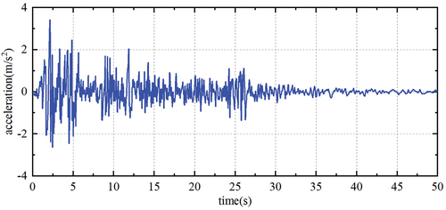
are the parameters of mass, stiffness, and damping for each story, respectively; The El Centro 1940 far-filed record is selected, the peak is 3.417
, the duration is 50 s, and the sampling step is 0.02 s. As shown in .
Figure 1. El Centro 1940 ground-acceleration seismic record.
The building motion under seismic excitation can be formulated as
where, ,
,
are the matrices of mass, stiffness, and damping, respectively;
,
,
represent the vectors of displacement, velocity, and acceleration for each story, respectively,
indicates the vector of control location,
denotes the control force matrix,
is the matrix of external disturbance input,
is the vector of external excitation.
The matrices of mass, stiffness, and damping have the following forms:
the damping matrix is obtained by substituting the stiffness parameters in
with their corresponding damping parameters.
Using the inter-story actuation scheme, the form of (Palacios-Quiñonero et al. Citation2019) is
the matrix of external disturbance input has the following form:
Considering the state vector,
by substituting it into EquationEq (24(24)
(24) ), the equation of motion for the structure can be transformed into the state-space model, which is given by:
where ,
,
represent the matrices of state, control, and disturbance input, respectively, the specific forms are
A new state vector can be defined at this stage, which converts the displacements and velocities of
into the corresponding inter-story drifts and inter-story velocities. Here,
then the new state-space model is
where ,
,
.
4.2. Design of the controllers
To solve the problem using a state feedback control strategy, the corresponding parameters of the controlled output are chosen as follows:
The parameter is adjustable and set to
, it generally needs reasonable setting to obtain appropriate control effect. Solving the optimization problem
in EquationEq (6
(6)
(6) ) results in the optimal value of
, denoted as
, and the accompanying state feedback gain matrix is
.
When employing the static output feedback control strategy for solving, the feedback information corresponds to the velocity information, and the matrix becomes:
In this case, the measured output only contains the inter-story velocity of the structure. In the output feedback linear matrix inequality optimization problem
based on the state feedback results, the parameters of the controlled output
are chosen using the same state feedback control strategy. By solving EquationEq (16
(16)
(16) ), the optimal value of
, denoted as
, is obtained, and the corresponding output feedback gain matrix
is also obtained.
The iterative output feedback control strategy is utilized to tackle the problem. The selection of is identical to the static output feedback strategy, while the selection of the controlled output parameters is the same as the state feedback control strategy. Once iteration is completed, the optimal values of
are displayed in ,
Table 1. for each iteration step.
According to the table content, the calculation is terminated when the iteration reaches the lower bound, and the corresponding iterative output feedback gain matrix is obtained.
The frequency response plots for the aforementioned three methods are computed and displayed in .
Figure 2. Maximum singular values of the FRFs. (a) overall view. (b) close view.
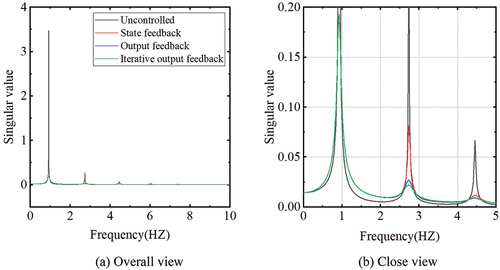
When compared to the uncontrolled building, all three control methods significantly produce a remarkable reduction of the main resonant peak, and exhibit superior attenuation effects on the first-order intrinsic frequency. The local plot of the frequency response shows that for the second-order intrinsic frequency position, the iterative output feedback control strategy manifests the best attenuation effect, followed by the output feedback control strategy, with the state feedback control strategy exhibiting slightly inferior performance.
4.3. Seismic response analysis
To substantiate the proposed iterative output feedback control strategy’s efficacy, the dynamic responses of the three control approaches are evaluated, and their results are compared. The maximum inter-story drifts, maximum absolute displacements, maximum absolute accelerations, and maximum control forces of the building are presented in , respectively.
Figure 3. Maximum inter-story drifts.
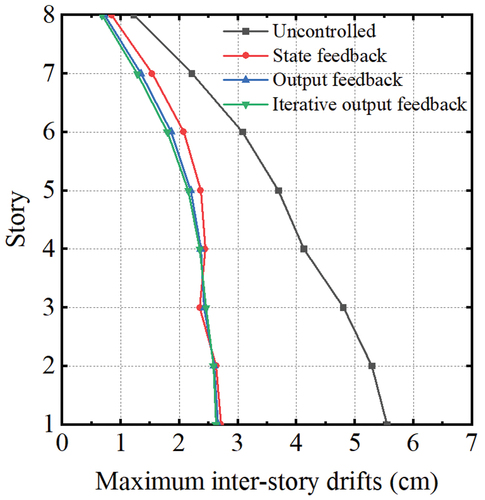
Figure 4. Maximum absolute displacements.
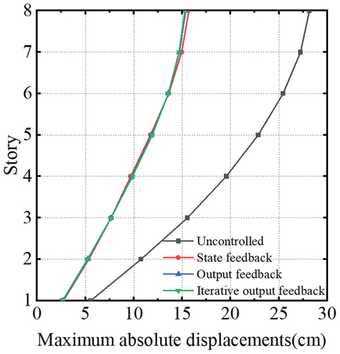
Figure 5. Maximum absolute accelerations.
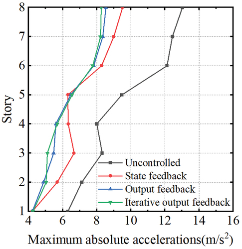
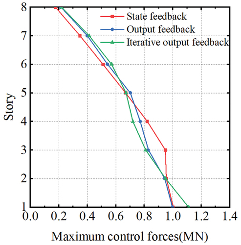
Figure 6. Maximum control forces.
The average control rate is calculated by
where and
are the maximum response of each layer with and without control devices, respectively. records some of the seismic dynamic response results, with cases 1, 2, 3, and 4 representing the four strategies: no control, state feedback, output feedback, and iterative output feedback, respectively.
Table 2. Partial record of seismic dynamic response results.
indicate that all three control methods produced favorable control outcomes. The inter-story drift’s average control rates for state feedback, output feedback, and iterative output feedback are 43.5%, 46.1%, and 46.9%, respectively, while the average control rates of absolute displacement are 47.5%, 47.8%, and 47.9%, respectively.
illustrates that all three control strategies showcase impressive control effects. The average acceleration control rates for state feedback, output feedback, and iterative output feedback are 27.1%, 33.1%, and 33.8%, respectively.
demonstrates that the control forces of all three control methods are virtually equivalent, implying that the proposed iterative output feedback control strategy exhibits superior performance to that of the state feedback and output feedback control approaches when matched by comparable control forces.
The time-history curves of the inter-story drift and absolute acceleration of the top layer of the building are presented in , respectively.
Figure 7. The time-history curves of the inter-story drift in the top layer.
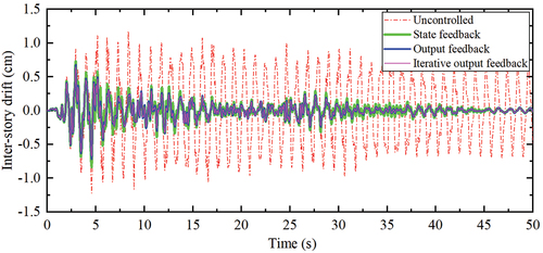
Figure 8. The time-history curves of the absolute acceleration in the top layer.
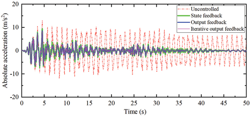
The effectiveness of all control strategies in mitigating inter-story drifts and accelerations at the top of the structure during the seismic excitation’s continuous action time is evident in . As time progresses, the response diminishes and eventually stabilizes. Both the output feedback and iterative output feedback energy-to-peak control strategies are significantly superior to state feedback control. Furthermore, the control effect of the iterative output feedback energy-to-peak control strategy can surpass that of the energy-to-peak output feedback strategy.
Based on reference (Ohtori et al. Citation2004), the subsequent two evaluation indicators are presented in the following manner.
Where is the inter-story drift of the above ground level over the time history of each earthquake,
is the height of each story,
is the maximum inter-story drift ratio of the uncontrolled structure, i.e.,
;
is the absolute acceleration of each story with control devices,
is the maximum absolute acceleration of the uncontrolled structure. contains the recorded results of the evaluation indicators for the three strategies.
Table 3. Results of evaluation indicators for different control strategies.
As demonstrated by the data in , the iterative output feedback strategy exhibits smaller evaluation indicators compared to the other two strategies, with clear superiority of control.
5. Conclusion
An iterative output feedback energy-to-peak control method is introduced in this paper by merging the iterative output feedback strategy and energy-to-peak control algorithm. A numerical simulation study on the response of an 8-story building structure to earthquake excitation is executed, and the resulting conclusions are as follows:
The iterative output feedback energy-to-peak control method is simple and effective. By iterating the linear matrix inequality procedure to obtain a suboptimal solution for the control problem, the iterative output feedback energy-to-peak control method overcomes the numerical solution difficulty in the bilinear matrix inequality constraint problem. After an uncomplicated initialization and numerical iteration process, the method achieves an improved static output feedback gain matrix.
The iterative output feedback energy-to-peak control method significantly produce a remarkable reduction of the main resonant peak. The frequency response function results reveal that the state feedback, output feedback, and iterative output feedback energy-to-peak control strategies demonstrate superior effectiveness in reducing the first-order intrinsic frequency peak of the structure. Additionally, the iterative output feedback energy-to-peak control approach is more effective than the other two methods in suppressing the second-order intrinsic frequency peak of the structural response.
When the control forces are in proximity, the iterative output feedback energy-to-peak control method surpasses the state feedback and output feedback energy peak control methods in terms of vibration mitigation.
The iterative output feedback energy-to-peak control method manages to steer clear of the controller’s over-reliance on external feedback information, thereby enabling the effective control of the system with only partial access to external observations. It is evidently envisaged that this method has the potential for bridges and floors applications, an in-depth study can be conducted in response to the relevant literature (Wang et al. Citation2020, Citation2021, Citation2023).
Disclosure statement
No potential conflict of interest was reported by the author(s).
Additional information
Funding
Notes on contributors
Qinghu Xu
Qinghu Xu, Ph.D., School of Civil Engineering, Anhui Jianzhu University, Hefei, China
Xiang Ruan
Xiang Ruan, Master Candidate, School of Civil Engineering, Anhui Jianzhu University, Hefei, China
Jianhao Wei
Jianhao Wei, Master Candidate, School of Civil Engineering, Anhui Jianzhu University, Hefei, China
References
- Ahmed, M., M. Abba-Gana, A. Ibrahim, S. A. Jalo, U. B. Bapetel, and G. Elhassan. 2020. “Improved PID Controller for Suppression of Vibrations in Buildings[c].” IEEE International Conference on Automatic Control and Intelligent Systems (I2CACIS). IEEE, p. 148–152. https://doi.org/10.1109/I2CACIS49202.2020.9140088.
- Al-Fahdawi, O. A. S., and L. R. Barroso. 2021. “Adaptive Neuro-Fuzzy and Simple Adaptive Control Methods for Full Three-Dimensional Coupled Buildings Subjected to Bi-Directional Seismic Excitations.” Engineering Structures 232:111798. https://doi.org/10.1016/j.engstruct.2020.111798.
- Chandiramani, N. K. 2016. “Semiactive Control of Earthquake/Wind Excited Buildings Using Output Feedback.” Procedia Engineering 144:1294–1306. https://doi.org/10.1016/j.proeng.2016.05.127.
- Chen, C. J., Z. H. Li, J. Teng, Q.-G. Wu, and B.-C. Lin. 2021. “A Variable Gain State-Feedback Technique for an AMD Control System with Stroke Limit and Its Application to a High-Rise Building.” The Structural Design of Tall & Special Buildings 30 (1): e1816. https://doi.org/10.1002/tal.1816.
- Hao, Y., and Z. Duan. 2017. “Structured Output-Feedback Controller Synthesis with Design Specifications.” International Journal of Systems Science 48 (4): 738–749. https://doi.org/10.1080/00207721.2016.1212432.
- Johansen, J. D. 2008. Active Control of Frame Structures: A Decentralized Approach [D]. Santa Barbara: University of California.
- Kazemy, A., É. Gyurkovics, and T. Takács. 2020. “Dynamic Output Feedback H ∞ Design in Finite-Frequency Domain for Constrained Linear Systems.” ISA Transactions 96:185–194. https://doi.org/10.1016/j.isatra.2019.06.005.
- Kazemy, A., X. M. Zhang, and Q. L. Han. 2017. “Dynamic Output Feedback Control for Seismic-Excited Buildings.” Journal of Sound and Vibration 411:88–107. https://doi.org/10.1016/j.jsv.2017.08.017.
- Lan, Q., X. Zhang, Y. Li, J. Mu, W. Zhu, and H. Xu. 2020. “Output Feedback Disturbance Rejection Control for Building Structure Systems Subject Seismic Excitations.” Measurement and Control 53 (9–10): 1616–1624. https://doi.org/10.1177/0020294020959743.
- Li, Z., C. Chen, J. Teng, J. Dong, and B. Lin. 2019. “A State Feedback Controller Based on GCC Algorithm Against Wind-Induced Motion for High-Rise Buildings with Parametric Uncertainties.” Shock and Vibration 2019:1–14. https://doi.org/10.1155/2019/3678258.
- Li, Z. H., C. J. Chen, and J. Teng. 2019. “A Multi-Time-Delay Compensation Controller Using a Takagi–Sugeno Fuzzy Neural Network Method for High-Rise Buildings with an Active Mass Damper/Driver System.” The Structural Design of Tall & Special Buildings 28 (13): e1631. https://doi.org/10.1002/tal.1631.
- Ohtori, Y., R. E. Christenson, B. F. Spencer, and S. J. Dyke. 2004. “Benchmark Control Problems for Seismically Excited Nonlinear Buildings.” Journal of Engineering Mechanics 130 (4): 366–385. 2004)130:4(366. https://doi.org/10.1061/(ASCE)0733-9399(2004)130:4(366).
- Palacios Quiñonero, F., J. Rubió Massegú, J. M. Rossell Garriga, S. A. Jalo, U. B. Bapetel, and G. Elhassan. 2019. “Interstory-Interbuilding Actuation Schemes for Seismic Protection of Adjacent Identical Buildings.” Smart Structures and Systems 24 (1): 67–81. https://doi.org/10.12989/sss.2019.24.1.067.
- Palacios-Quiñonero, F., J. Rubió-Massegú, J. M. Rossell, and H.R. Karimi. 2019. “An Iterative Linear Matrix Inequality Controller-Design Strategy for H∞ Structural Vibration Control[c].” Advances in Engineering Materials, Structures and Systems: Innovations Mechanics and Applications: Proceedings of the 7th International Conference on Structural Engineering, Mechanics and Computation (SEMC 2019), September 2-4, 2019, Cape Town, South Africa. CRC Press, pp. 49. https://doi.org/10.1201/9780429426506.
- Palacios-Quiñonero, F., J. Rubió-Massegú, J. M. Rossell, and H. R. Karimi. 2014. “Optimal Design of Complex Passive-Damping Systems for Vibration Control of Large Structures: An Energy-To-Peak Approach[c]//Abstract and Applied Analysis.” Abstract and Applied Analysis 2014:1–9. https://doi.org/10.1155/2014/510236.
- Palacios-Quiñonero, F., J. Rubió-Massegú, J. M. Rossell, and H. R. Karimi. 2017. “LMI-Based Design of Distributed Energy-Dissipation Systems for Vibration Control of Large Multi-Story Structures.” Procedia Engineering 199:1749–1754. https://doi.org/10.1016/j.proeng.2017.09.433.
- Rahmani, B., A. Ziaiefar, and S. Hashemi. 2022. “Output Feedback-Based Adaptive Fuzzy Sliding Mode Control for Seismic Response Reduction of Base-Isolated Buildings.” ISA Transactions 126:94–108. https://doi.org/10.1016/j.isatra.2021.07.021.
- Rubió-Massegú, J., F. Palacios-Quiñonero, J. M. Rossell, and H. R. Karimi. 2020. “A Novel Iterative Linear Matrix Inequality Design Procedure for Passive Inter-Substructure Vibration Control.” Applied Sciences 10 (17): 5859. https://doi.org/10.3390/app10175859.
- Rubió-Massegú, J., J. M. Rossell, H. R. Karimi, and F. Palacios-Quiñonero. 2013. “Static Output-Feedback Control Under Information Structure Constraints.” Automatica 49 (1): 313–316. https://doi.org/10.1016/j.automatica.2012.10.012.
- Runge, J., and R. Zmeureanu. 2019. “Forecasting Energy Use in Buildings Using Artificial Neural Networks: A Review.” Energies 12 (17): 3254. https://doi.org/10.3390/en12173254.
- Sadabadi, M. S., and D. Peaucelle. 2016. “From Static Output Feedback to Structured Robust Static Output Feedback: A Survey.” Annual Reviews in Control 42:11–26. https://doi.org/10.1016/j.arcontrol.2016.09.014.
- Saeed, M. U., Z. Sun, and S. Elias. 2022. “Semi-Active Vibration Control of Building Structure by Self Tuned Brain Emotional Learning Based Intelligent Controller.” Journal of Building Engineering 46:103664. https://doi.org/10.1016/j.jobe.2021.103664.
- Wang, L., S. Nagarajaiah, W. Shi, and Y. Zhou. 2020. “Study on Adaptive-Passive Eddy Current Pendulum Tuned Mass Damper for Wind-Induced Vibration Control.” The Structural Design of Tall & Special Buildings 29 (15): e1793. https://doi.org/10.1002/tal.1793.
- Wang, L., S. Nagarajaiah, W. Shi, and Y. Zhou. 2021. “Semi-Active Control of Walking-Induced Vibrations in Bridges Using Adaptive Tuned Mass Damper Considering Human-Structure-Interaction.” Engineering Structures 244:112743. https://doi.org/10.1016/j.engstruct.2021.112743.
- Wang, L., S. Nagarajaiah, W. Shi, and Y. Zhou. 2022. “Seismic Performance Improvement of Base-Isolated Structures Using a Semi-Active Tuned Mass Damper.” Engineering Structures 271:114963. https://doi.org/10.1016/j.engstruct.2022.114963.
- Wang, L., S. Nagarajaiah, Y. Zhou, and W. Shi. 2023. “Experimental Study on Adaptive-Passive Tuned Mass Damper with Variable Stiffness for Vertical Human-Induced Vibration Control.” Engineering Structures 280:115714. https://doi.org/10.1016/j.engstruct.2023.115714.
- Wang, L., W. Shi, X. Li, Q. Zhang, and Y. Zhou. 2019. “An Adaptive-Passive Retuning Device for a Pendulum Tuned Mass Damper Considering Mass Uncertainty and Optimum Frequency.” Structural Control and Health Monitoring 26 (7): e2377. https://doi.org/10.1002/stc.2377.
- Wang, L., W. Shi, Z. Ying, and Q. Zhang. 2020. “Semi-Active Eddy Current Pendulum Tuned Mass Damper with Variable Frequency and Damping.” Smart Structures and Systems 25:65–80. https://doi.org/10.12989/sss.2020.25.1.065.
- Wang, L., W. Shi, Q. Zhang, and Y. Zhou. 2020. “Study on Adaptive-Passive Multiple Tuned Mass Damper with Variable Mass for a Large-Span Floor Structure.” Engineering Structures 209:110010. https://doi.org/10.1016/j.engstruct.2019.110010.
- Wang, L., W. Shi, and Y. Zhou. 2019. “Study on Self-Adjustable Variable Pendulum Tuned Mass Damper.” The Structural Design of Tall & Special Buildings 28 (1): e1561. https://doi.org/10.1002/tal.1561.
- Wang, L., W. Shi, and Y. Zhou. 2022. “Adaptive-Passive Tuned Mass Damper for Structural Aseismic Protection Including Soil–Structure Interaction.” Soil Dynamics and Earthquake Engineering 158:107298. https://doi.org/10.1016/j.soildyn.2022.107298.
- Wang, L., Y. Zhou, S. Nagarajaiah, and W. Shi. 2023. “Bi-Directional Semi-Active Tuned Mass Damper for Torsional Asymmetric Structural Seismic Response Control.” Engineering Structures 294:116744. https://doi.org/10.1016/j.engstruct.2023.116744.
- Wang, L., Y. Zhou, and W. Shi. 2023a. “Seismic Control of a Smart Structure with Semiactive Tuned Mass Damper and Adaptive Stiffness Property.” Earthquake Engineering and Resilience 2 (1): 74–93. https://doi.org/10.1002/eer2.38.
- Wang, L., Y. Zhou, and W. Shi. 2023b. “Seismic Response Control of a Nonlinear Tall Building Under Mainshock-Aftershock Sequences Using Semi-Active Tuned Mass Damper.” International Journal of Structural Stability and Dynamics. https://doi.org/10.1142/S0219455423400278.
- Xu, Q., X. Zhen, X. Ruan, Y. Liu, X. Shi, D. Man, X. Kang, and G. Xia. 2022. “The Research of the Overlapping Decentralized Guaranteed Cost Hybrid Control Method for Adjacent Buildings with Uncertain Parameters.” Mathematical Problems in Engineering 2022:1–14. https://doi.org/10.1155/2022/1143374.
- Yang, D., X. Li, and J. Qiu. 2019. “Output Tracking Control of Delayed Switched Systems via State-Dependent Switching and Dynamic Output Feedback.” Nonlinear Analysis: Hybrid Systems 32:294–305. https://doi.org/10.1016/j.nahs.2019.01.006.
- Zecevic, A. I., and D. D. Siljak. 2004. “Design of Robust Static Output Feedback for Large-Scale Systems.” IEEE Transactions on Automatic Control 49 (11): 2040–2044. https://doi.org/10.1109/TAC.2004.837542.