
Abstract
Polymer-stabilised blue phase liquid crystal displays (PS-BPLCD) based on Kerr effect have become an increasingly important technology for information display applications. In comparison with conventional nematic LC devices, BPLCs exhibit several attractive features, such as sub-millisecond grey-to-grey response time, reasonably wide temperature range, no need for alignment layer, optically isotropic voltage-off state and large cell gap tolerance. However, some technical challenges such as high operation voltage, hysteresis, residual birefringence and relatively low transmittance remain to be overcome before their widespread applications can be realised. Recent progress on BPLC materials and devices has shown great promise. From material aspect, the electro-optical properties of blue phase liquid crystal material system are studied. To realise the electro-optic effect of PS-BPLC, novel device configurations that can dramatically improve the display performances are designed.
1. Introduction
From cell phones, laptops, desktops, TVs to projectors, high-reliability liquid crystal displays (LCDs) have become indispensable in our daily life. Tremendous progress in LCDs has been made after decades of extensive research and development in materials, device configurations and manufacturing technology.[Citation1]
Nowadays, the most critical issue on viewing angle has been solved using multi-domain structures [Citation2–Citation4] and optical film compensation.[Citation5,Citation6] Slow response time has been improved to 2–5 ms with low-viscosity LC material, overdrive and undershoot voltage, and thin cell gap approach. Moving image blur has been significantly reduced by impulse driving and frame insertion.[Citation7] Contrast ratio in excess of 1 million-to-1 has been achieved through local dimming of the segmented LED backlight.[Citation8–Citation10] The colour gamut would exceed 100% of the NTSC (National Television System Committee), if RGB LEDs are used.[Citation11] Besides these technological advances, the cost has been reduced dramatically by investing in advanced manufacturing technologies.
Polymer-stabilised blue phase liquid crystal displays (PS-BPLCDs) based on Kerr effect is emerging as a potential next-generation display technology. In comparison with conventional nematic devices, the PS-BPLCDs exhibit following attractive features: (1) sub-millisecond response time, (2) no need for molecular alignment layers, (3) optically isotropic dark state when sandwiched between crossed polarisers, and (4) transmittance is insensitive to cell gap when the in-plane electrodes are employed.[Citation12,Citation13] Therefore, BPLC holds promises for fast-response transmissive display, reflective display and photonics applications.
In this paper, we will review of the properties of PS-BPLC materials system and discuss the device operation mechanisms of LCDs based on the Kerr effect. New BPLC device structures are introduced to optimise display performances.
2. Properties of PS-BPLC
2.1. PS-BPLC appearance and material system
Blue phase is a distinct thermodynamic phase that appears over a narrow temperature range (1–2°C) between the chiral-nematic/cholesteric (CH) and isotropic phases. Depending on the structure, there are up to three blue phases: BP-I, BP-II and BP-III. BP-I and BP-II exhibit 3-D periodic structures in the director field as shown in . They have body-centred and simple cubic symmetry, respectively. BP-III is seemingly amorphous; it has a same symmetry as the isotropic phase.[Citation14]
Figure 1. Cubic structures of BP-I and BP-II.
is the molecular structure of blue phase LC with cubic structure. The liquid crystal molecules have a double-twist alignment filled up in a cylinder. There is in fact unlimited number of helical axes presented; however, the structure was named double-twist. The LC directors perform a 45° rotation from the centre line. Due to the orientation of the LC molecules, microscopically, blue phase is optically anisotropic. The diameter of the cylinder is in the range the pitch length of the chiral nematic LC of ~100 nm. Because of this small range local reorientation, blue phase has a very fast response. So far, a microsecond-response BPLC with 39-µs decay time at room temperature has been demonstrated.[Citation15] The double-twist cylinders further form the cubic symmetry; therefore, blue phase is optically isotropic macroscopically. The double-twist alignment is more stable than the single-twist structure such as the chiral nematics with normal helical structure. However, the double-twist cylinders cannot fill the cubic space completely uniformly to allow the directors to be matched everywhere. Meiboom has introduced the defect theory that defects occur at the intersections between the double-twist cylinders in the cubic structure.[Citation16]The cubic structure of blue phase is stabilised by the lattice defects. The disclination lines in (d) are the defect lines.
Figure 2. Blue phase LC structure at the microscopic level: (a) double-twist alignment of LC molecules; (b) double-twist cylinder; (c) lattice cubic symmetry formed by double-twist cylinders and (d) disclination lines of singularity in molecular alignment.
The temperature range in which the defect structure exists is very narrow (around 1–2°C) and is an issue problem from the viewpoint of practical applications. In 2002, Kikuchi proposed a polymer stabilisation method in which an equilibrium phase is thermodynamically stabilised by the coexistence of a polymer. Polymer chains are formed selectively in the disclination core, and therefore, the blue phase composite does not require a thermal energy to keep the disclination core isotropic at a temperature below isotropic phase. Through this method, the temperature range is reported to be expanded to more than 60° including room temperature.[Citation17]
A PS-BPLC precursor typically comprises of 70–90 wt% of nematic LC host as switching molecules, 5–10 wt% of chiral dopant to induce blue phase, and 8–15 wt% of photocurable monomers and ~1% of photoinitiator for polymer stabilisation. To form BPLC composite, the precursor is cooled from isotropic phase to blue phase and then exposed to UV light. After UV irradiation, PS-BPLC nano-composites are self-assembled, exhibiting the characteristic small platelet structures.
2.2. Kerr effect
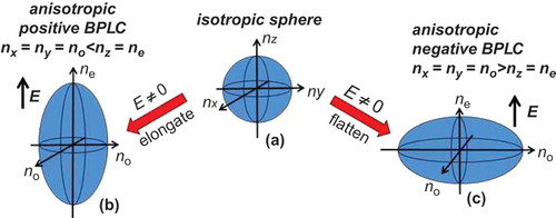
Kerr effect is a type of quadratic electro-optic effect caused by an electric-field-induced ordering of polar molecules in an optically isotropic medium. It usually exists in crystals with centro-symmetric point groups. If an electric field E is applied to a Kerr medium, such as PS-BPLC or optically isotropic LC composite, birefringence will be induced which is related to E as [Citation18]:
The induced anisotropy will be along the direction of the electric field. Consequently, the isotropic sphere will appear as an elongated () or a flattened () ellipsoid, depending on whether the host LC has a positive or negative dielectric anisotropy (∆ε).[Citation19] Equation (1) is valid only when the electric field is weak. As E keeps increasing, the induced birefringence will gradually saturate, as clearly described by the following extended Kerr effect [Citation20]:
It has been reported by Gerber that the Kerr constant can be approximated by the following equation [Citation21]:
Figure 3. Electro-optic effect on BPLC refractive index ellipsoid: (a) BPLC without an electric field, (b) positive ∆ε BPLC with an electric field and (c) negative ∆ε BPLC with an electric field.
As is discussed in detail later, Kerr constant plays a key role on the operating voltage of the BPLC devices. A typical Kerr constant of BPLC composite is around 1 nm/V2. In 2009, Kikuchi et al. [Citation24] reported a polymer-stabilised isotropic phase composite with K ~ 10 nm/V2 and its operating voltage in an IPS cell (5-μm electrode width and 10-μm electrode gap) is ~50 Vrms.
2.3. Response time
Fast response time is one of the most attractive features of PSBP LC since it helps to reduce motion blur and enable colour-sequential display while minimising colour break-up. shows the response time data from a paper by L. Rao about the prospects of PS-BPLCD.[Citation25] The decay time is defined as 100–10% transmittance change.
Figure 4. Temperature-dependent decay time. Dots are experimental data and line represents fitting using exponential curve in the paper.[Citation25]
![Figure 4. Temperature-dependent decay time. Dots are experimental data and line represents fitting using exponential curve in the paper.[Citation25]](/cms/asset/637f0130-3795-43cc-9e82-4dbb7a172770/tlcy_a_973270_f0004_c.jpg)
As the temperature increases, the decay time decreases rapidly. At room temperature, the response time of BPLC is indeed experimentally shown being sub-millisecond. For example, we note from that the response time is decreased by 2X when the temperature is increased by merely 4–5°. This changing rate is ~3X more sensitive than that of most nematic LCs.
To understand this phenomenon, a physical model has been developed to explicitly correlate the temperature-dependent response time with LC parameters. The free relaxation time of a polymer-stabilised blue phase or optically isotropic LC composite can be approximated by [Citation1,Citation26]:
From mean field theory,[Citation23] elastic constant is related to the nematic order parameter (S) as . With regard to rotational viscosity, the following modified Arrhenius model works well to describe the temperature-dependent rotational viscosity of nematic LCs [Citation27,Citation28]:
3. PS-BPLC for displays
3.1. Blue phase liquid crystal displays with in-plane-switching fields
Typically, for display applications, the LC layer is sandwiched between two crossed linear polarisers. The operation mechanism of a PS-BPLCD is drastically different from conventional nematic LCDs in that the former is based on Kerr effect-induced isotropic-to-anisotropic transition while the latter relies on the anisotropic-to-anisotropic LC director reorientation. Moreover, the optic axis of the induced birefringence in BPLC is along the direction of the electric field. To achieve effective phase retardation, the induced birefringence should be parallel to the BPLC cell substrates, that is, a lateral electric field is desired. Among the present LCD modes, in-plane-switching (IPS) LCD can effectively generate horizontal electric fields; therefore, in blue phase LCD devices, IPS electrodes are commonly employed.[Citation29]
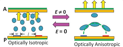
illustrates the basic operation principles of a BPLCD in a planar IPS cell, where w is the electrode width and l is the electrode gap. When there’s no electric field applied, the symmetric cubic structure in a PS-BPLC appears to be optically isotropic. Therefore, the linearly polarised light passing the bottom polariser experiences no phase retardation in the BPLC layer; thus, it cannot pass the crossed analyser. When an electric field is applied, the BPLC becomes anisotropic according to the Kerr effect; thus, the linearly polarised light passing the bottom polariser can pass the analyser on the top.
Figure 5. Operation principle of a BPLCD. Left: without electric field, BPLC appears to be optically isotropic; right: with electric field, BPLC becomes optically anisotropic.
The output transmittance of a uniaxial medium placed between two crossed linear polarisers is , where ϕ is the angle between optic axis of the uniaxial media and the absorption axis of the polariser, δ = 2d∆n/λ is the phase retardation of the uniaxial medium. The angle ϕ needs to be 45° away from the linear polariser absorption axis in order to obtain maximum transmittance. In other words, the induced ∆n also needs to be along that direction to have a maximum transmittance. Moreover, to get the maximum phase retardation δ, the induced birefringence should also be along the horizontal direction parallel to the substrate surface. Therefore, the stronger horizontal fields will benefit.
However, in a conventional IPS electrode configuration, the electric field is confined near the surface, and only the LC molecules in this shallow region contribute to the induced birefringence. As a result, the required voltage is high and transmittance is low. Even with a large Kerr constant of 13.7 nm/V2 (Chisso JC-BP01M), the on-state voltage is still as high as ~50 V at room temperature, which is too high for amorphous-silicon thin-film transistors (a-Si TFTs).[Citation30] Therefore, there is an urgent need to address this critical issue of high driving voltage.
3.2. BPLCDs with protrusion electrodes
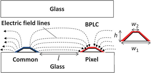
To reduce the operating voltage, deeper penetration into the LC bulk region is needed. In the conventional planar IPS structure, we could strengthen the horizontal electric field by reducing the electrode gap. However, as the electrode gap becomes narrower, the penetration depth becomes shallower. The trade-off is the reduced optical efficiency. is proposed protruded electrode design with trapezoid shape.[Citation31] The BPLC layer is interposed between two glass substrates, which are further sandwiched between two crossed polarisers; pixel and common electrodes are made with the trapezoid-shaped protrusion structure. The trapezoid dimension is defined as follows: w1 is the bottom width, w2 is the top width, h is the height and l is the space between common and pixel electrodes. The protrusion structures have been widely used in multi-domain vertical alignment LCDs for obtaining wide viewing angle.[Citation19] Besides, it can be made transparent with organic positive photoresist so the aperture ratio of the LC panel will not be sacrificed. In this design, the induced birefringence on top of the electrode does not contribute to the transmittance since the electric field is almost vertical. But compared with traditional IPS structure, stronger horizontal electric fields are generated between the pixel and common electrodes. Moreover, the field is able to penetrate deeply into the LC bulk region. The former plays a key role to reduce operating voltage while the latter helps to achieve high transmittance. This explains why a much lower on-state voltage is needed for the protruded electrode design.
Figure 6. BPLCD structure with trapezoid-shaped protrusion electrodes and electric field lines.
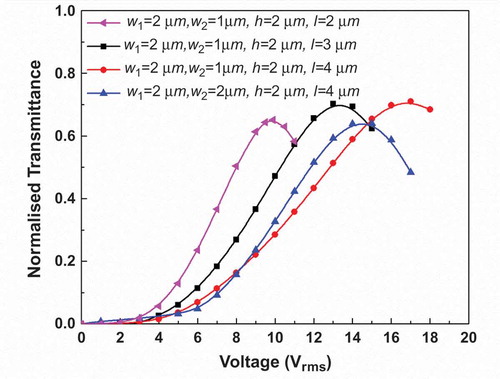
For the protruded electrode with w1 = 2 μm, w2 = 1 μm, h = 2 μm and l = 4 μm shown in , the peak transmittance is ~71% (normalised to the transmittance of two parallel polarisers) at 17 Vrms. Compared to the conventional IPS structure with electrode width w = 2 μm and electrode gap l = 4 μm (designated as IPS 2-4) with Von ~ 38 Vrms and peak transmittance ~66.5%, our protrusion electrode shows a significant reduction in driving voltage while maintaining a relatively high transmittance.
Figure 7. Normalised VT curves for protrusion electrodes with different dimensions.
To understand the underlying physics, we plot in the effective induced-birefringence (δneff) distribution for the protrusion electrode structure and IPS 2-4 structure. δneff is the effective birefringence that the normal incident light experiences. It is different from the induced birefringence ∆n in Equation (1), which is the overall induced-birefringence of the BPLC material regardless of the electric field direction and the effectiveness whether the ∆n will contribute to the transmittance.
Figure 8. Induced effective birefringence (δneff) distribution for (a) conventional IPS cell with strip electrode with electrode width w = 2 μm, spacing l = 4 μm, and cell gap d = 10 μm, and (b) protrusion electrode with w1 = 2 μm, w2 = 1 μm, h = 4 μm and l = 4 μm, cell gap d = 10 μm.
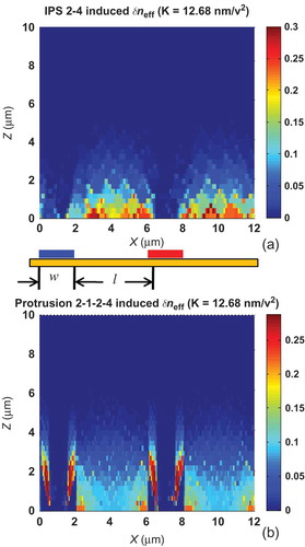
From , δneff is almost zero on top of the electrode for both structures since the electric field there is almost vertically distributed so that it does not provide phase change for the normal incident light. Nevertheless, the protrusion structure has a thicker penetrating depth and a larger δneff value in the effective region. This is the reason why a much lower on-state voltage is needed for the protrusion electrode design.
also shows the influence of electrode dimension on the voltage-dependent transmittance (VT) curve. Different electrode dimension generates different electric fields distribution in the BPLC cell. In comparison with the structure with parameters: w1 = 2 μm, w2 = 1 μm, h = 2 μm and l = 4 μm, if the spacing width l is decreased to 3 or 2 μm, then the on-state voltage is lowered to 13 or 9.9 Vrms, respectively. This is attributed to the stronger electric field generated as the electrode gap gets smaller. However, the trade-off is the lower transmittance. This is because the effective volume with horizontal electric field that accumulates the phase for the transmittance is smaller. If the size of w2 is increased to 2 μm, the electric field near the bottom of the cell will be more uniformly distributed in horizontal direction. As a result, denoted by the black line in , the operating voltage is reduced to 12 Vrms. Again, the trade-off will be that the transmittance is lower since larger w2 reduces the effective spacing area between the electrodes. If we increase the protrusion height h to 4 μm, the peak transmittance would increase to 74.2% at 13 Vrms. The electric field in this case is stronger and more uniform as compared to the one with a 2-μm height. Therefore, a lower driving voltage is needed. Meanwhile, the penetration of electric field gets deeper into the LC medium which enhances the transmittance. However, a 4-μm height protrusion electrode may be difficult to fabricate.
In the voltage-off state, blue phase LC is optically isotropic so the dark state is very good. We have calculated the iso-contrast contours for the protrusion electrode structure with dimensions of d = 10 μm, w1 = 2 μm, w2 = 1 μm, h = 2 μm, l = 4 μm and λ = 550 nm. The contrast ratio (CR) of 200:1 is over 30° without any compensation film in . In , adding a half-wave biaxial film greatly suppresses the off-axis light leakage of the two crossed polarisers, so that CR = 1000:1 can reach about 60°. This result is even better than that of the strip-electrode IPS BPLC cell we reported previously because the peak transmittance for the protrusion electrode is slightly higher. While blue phase liquid crystals have a really good dark state, the CR is mainly governed by the on-state transmittance.
Figure 9. Iso-contrast plots of the BPLC cell with protrusion: (a) without compensation films and (b) with biaxial compensation films. The biaxial film parameters are: Nz = 0.5, R0 = (nx−ny).d = λ/2.
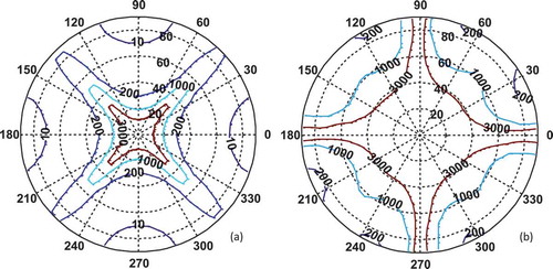
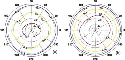
At off-angle incident, the vertical part of the field is no longer vertical to the incident light, so the curved electric field will compensate the transmittance. shows the angular dependent (azimuthal and polar) light transmittance for (a) strip electrode (parameters: electrode width w = 2 μm and spacing width l = 4 μm) and (b) protrusion electrode (parameters: w1 = 2 μm, w2 = 1 μm, h = 2 μm and l = 4 μm). The polar angle of the protrusion structure with a transmittance of ~60% is over 50° while the strip electrode structure is only ~30°. The increasingly curved electric field in z-direction of protrusion electrode compensates more than the strip electrodes due to its deeper penetration layer into the LC bulk region. The iso-brightness contour plots in match the induced effective birefringence distribution in .
Figure 10. Angular-dependent (azimuthal and polar) light transmittance for: (a) strip electrode (parameters: electrode width w = 2 μm and spacing l = 4 μm) and (b) protrusion electrode (parameters: w1 = 2 μm, w2 = 1 μm, h = 2 μm and l = 4 μm).
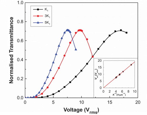
In addition to optimising the device structure for generating strong and deep electric fields, it is equally important to develop LC materials with a larger Kerr constant. depicts the simulated VT curves at λ = 550 nm under different Kerr constants (K1 = 12.68 nm/V2, K2 = 3K1, K3 = 5K1) for the protrusion electrode structure with dimensions of d = 10 μm, w1 = 2 μm, w2 = 1 μm, h = 2 μm and l = 4 μm. With the increased Kerr constant, the on-state voltage is reduced from 17 to 9.7 Vrms and to 7.5 Vrms. The low-voltage operation would reduce the power consumption of the display devices. Amazingly, the on-state voltage is linearly proportional to, although the electric field generated from the protrusion electrodes is not uniform. Shown in the insert of , the red line is the linear fitting for K1, K2, K3, K4 = 2K1, and K5 = 4.5K1 with the linear equation as [Citation30]:
Figure 11. VT curves with different Kerr constants for protrusion electrode structure with w1 = 2 μm, w2 = 1 μm, h = 4 μm and l = 4 μm, cell gap d = 10 μm, inset is the linear plot between on-state voltage and.
To illustrate the importance of device structure, we compared the planar IPS electrodes with protrusion electrodes. From a previous experiment described in paper,[Citation25] we have employed an IPS cell with a cell gap of 7.5 µm, and the ITO (indium tin oxide) electrode width of 10 µm and the electrode gap of 10 µm. We filled the same type of IPS cell with both the UCF BPLC material and Chisso BPLC material JC-BP01M. We find the device constant A is around 6 μm1/2. Here, compared to the planar IPS cell, the protrusion electrode reported in has a device proportionality constant A = 1.91 μm1/2, which indeed indicates that a small A coefficient helps to lower the operating voltage.
The protrusion electrode structure is a feasible configuration for dramatically reducing the operating voltage of blue phase LCDs while keeping a reasonably high transmittance. There are already prototypes manufactured with this type of electrodes from leading LCD manufacturers such as Samsung and SEL lab.[Citation32,Citation33] By optimising the protrusion structure, the operating voltage can be successfully reduced to ~10 Vrms. This is an important milestone because the device can be driven by a-Si TFTs. There are other effects in optimising the device configuration, structures like BPLCDs with double-penetrating fringing fields,[Citation34] with corrugated electrodes [Citation35] and with vertical field switching [Citation36] are proposed. With continuous development of large Kerr constant BPLC materials, the voltage can be reduced further.
4. Remaining challenges
Although polymer-stabilised isotropic-to-anisotropic LCDs hold great potentials for future display applications, some technical challenges remain to be overcome:
Low operating voltage: The protrusion electrodes substantially lower the operating voltage, but its fabrication complexity is increased. Simpler methods for reducing voltage while keeping high transmittance need to be developed.
New materials: PS-BPLC represents a paradigm shift in materials. The conventional TFT-grade nematic LCs require a modest birefringence (Δn ~ 0.1) and dielectric anisotropy (Δε ~ 5–10), low viscosity and high resistivity. However, to achieve a large Kerr constant (K ~ 10 nm/V2), the BPLC would need to have a high Δn (>0.2) and large Δε (>30). These compounds will have long molecular conjugation and large dipole moment. As a result, their viscosity will be high. Moreover, the PS-BPLC requires two types of monomers and photoinitiator. The ionic impurities in these monomers would degrade the voltage-holding ratio. The temperature range is another concern. For display applications, the LC temperature range should cover from −40 to 80°C. In PS-BPLC, we could choose a wide-temperature-range nematic LC host. However, after mixing with chiral dopant, the mixture’s clearing point often decreases substantially. For example, the clearing temperature of our LC host is 94°C, but it drops to 54°C after polymerisation. A low-clearing point will make the electro-optic properties of the LC/polymer composite very sensitive to the local temperature variation of a display panel, such as VT curves and response time. Consequently, the requirement for better thermal uniformity of a backlight unit is increased. A lot of new material development work (LC and monomers) along with the photopolymerisation process need to be studied.
Hysteresis: It is known that polymer-stabilised LCs often exhibit memory effect, also known as hysteresis. Some preliminary work on the hysteresis of BPLC and PS-BPLC has been reported [Citation37]. Hysteresis affects the accuracy of grey-scale control and should be minimised.
Long-term stability: The concerns of long-term stability include twofold: incomplete photopolymerisation process and device operating lifetime, such as image sticking and polymer stability.
Residual birefringence: During the polymerisation process, some LC molecules could be embedded in the polymer networks. If this residual birefringence is not uniformly distributed in the entire panel, it will be difficult to be compensated by an optical film. As a result, the display CR will be degraded.
5. Summary
PS-BPLC is emerging as a promising candidate for next-generation display and photonics devices. In this paper, we have reviewed the material system and electro-optic properties of PS-BPLC. The device optimisation for BPLCD is introduced that can successfully reduce the operating voltage to ~10 V. This is an important milestone as it enables the a-Si TFTs driving. With rapid advances in PS-BPLC materials and device structures, the widespread application of PS-BPLCs is foreseeable.
References
- Yang DK, Wu ST. Fundamentals of liquid crystal devices. New York (NY): Wiley; 2006.
- Takeda A, Kataoka S, Sasaki T, Chida H, Tsuda H, Ohmuro K, Sasabayashi T, Koike Y, Okamoto K. 41.1: A super-high image quality multi-domain vertical alignment LCD by new rubbing-less technology. SID Symp Dig. 1998;29:1077–1080. doi:10.1889/1.1833672.
- Oh-e M, Kondo K. Electro-optical characteristics and switching behavior of the in-plane switching mode. Appl Phys Lett. 1995;67:3895–3897. doi:10.1063/1.115309.
- Kim SG, Kim SM, Kim YS, Lee HK, Lee SH, Lee GD, Lyu JJ, Kim KH. Stabilization of the liquid crystal director in the patterned vertical alignment mode through formation of pretilt angle by reactive mesogen. Appl Phys Lett. 2007;90:2619110. doi:10.1063/1.2752105.
- Hong Q, Wu TX, Zhu X, Lu R, Wu S-T. Extraordinarily high-contrast and wide-view liquid-crystal displays. Appl Phys Lett. 2005;86:121107. doi:10.1063/1.1887815.
- Zhu X, Ge Z, Wu S-T. Analytical solutions for uniaxial-film-compensated wide-view liquid crystal displays. J Display Technol. 2006;2:2–20. doi:10.1109/JDT.2005.863599.
- Hong H, Shin H, Chung I. In-plane switching technology for liquid crystal display television. J Display Technol. 2007;3:361–370. doi:10.1109/JDT.2007.901562.
- Kim S. The world’s largest (82-in.) TFT-LCD. SID Symp Dig. 2005;36:1842–1847. doi:10.1889/1.2036378.
- Liu CT. Revolution of the TFT LCD technology. J Display Technol. 2007;3:342–350. doi:10.1109/JDT.2007.908348.
- Lu R, Wu S-T, Lee SH. Reducing the color shift of a multi-domain vertical alignment liquid crystal display using dual threshold voltages. Appl Phys Lett. 2008;92:051114. doi:10.1063/1.2838752.
- Lu R, Hong QI, Ge Z, Wu S-T. Color shift reduction of a multi-domain IPS-LCD using RGB-LED backlight. Opt Express. 2006;14:6243–6252. doi:10.1364/OE.14.006243.
- Ge Z, Gauza S, Jiao M, Xianyu H, Wu S-T. Electro-optics of polymer-stabilized blue phase liquid crystal displays. Appl Phys Lett. 2009;94:101104. doi:10.1063/1.3097355.
- Ge Z, Rao L, Gauza S, Wu ST. Modeling of blue phase liquid crystal displays. IEEE/OSA J Display Technol. 2009;5:250–256. doi:10.1109/JDT.2009.2022849.
- Crooker PP. Blue phases. In Kitzerow HS, Bahr C, editors. Chirality in liquid crystals. New York (NY): Springer; 2001.
- Chen Y, Yan J, Sun J, Wu S-T, Liang X, Liu S-H, Hsieh P-J, Cheng K-L, Shiu J-W. A microsecond-response polymer-stabilized blue phase liquid crystal. Appl Phys Lett. 2011;99:201105. doi:10.1063/1.3662391.
- Meiboom S, Anderson PW, Brinkman WF. Theory of the blue phase of cholesteric liquid-crystals. Phys Rev Lett. 1981;46:1216–1219. doi:10.1103/PhysRevLett.46.1216.
- Kikuchi H, Yokota M, Hisakado Y, Yang H, Kajiyama T. Polymer-stabilized liquid crystal blue phases. Nat Mater. 2002;1:64–68. doi:10.1038/nmat712.
- Kerr J. A new relation between electricity and light: dielectrified media birefringent. Philos Mag. 1875;50:337–348.
- Rao L, Ge Z, Wu S-T. Viewing angle controllable displays with a blue-phase liquid crystal cell. Opt Express. 2010;18:3143–3148. doi:10.1364/OE.18.003143.
- Yan J, Cheng H-C, Gauza S, Li Y, Jiao M, Rao L, Wu S-T. Extended Kerr effect of polymer-stabilized blue phase liquid crystals. Appl Phys Lett. 2010;96:071105. doi:10.1063/1.3318288.
- Gerber PR. Electro-optical effects of a small-pitch blue-phase system. Mol Cryst Liq Cryst. 1985;116:197–206. doi:10.1080/00268948508074573.
- Wu S-T. Birefringence dispersions of liquid-crystals. Phys Rev. 1986;33:1270–1274. doi:10.1103/PhysRevA.33.1270.
- Maier W, Saupe A. Eine einfache molecular-statistische theorie der nematischen kristallinflüssigen phase. Z Naturforsch Teil A. 1960;15:287–292.
- Kikuchi H, Haseba Y, Yamamoto S-I, Iwata T, Higuchi H. 39.1: invited Paper: optically isotropic nano-structured liquid crystal composites for display applications. SID Int Symp Digest Tech Papers. 2009;40:578–581. doi:10.1889/1.3256842.
- Rao L, Yan J, Wu S-T. Prospects of emerging polymer-stabilized blue-phase liquid-crystal displays. J Soc Inf Disp. 2010;18:954–959. doi:10.1889/JSID18.11.954.
- Gleeson HF, Coles HJ. Dynamic properties of blue-phase mixtures. Liq Cryst. 1989;5:917–926. doi:10.1080/02678298908026398.
- Wu S-T, Wu C-S. Experimental confirmation of the osipov-terentjev theory on the viscosity of nematic liquid-crystals. Phys Rev. 1990;42:2219–2227. doi:10.1103/PhysRevA.42.2219.
- Wu S-T, Wu C-S. Rotational viscosity of nematic liquid crystals: a critical examination of existing models. Liq Cryst. 1990;8:171–182. doi:10.1080/02678299008047339.
- Soref RA. Transverse field effects in nematic liquid crystals. Appl Phys Lett. 1973;22:165–166. doi:10.1063/1.1654597.
- Rao L, Yan J, Wu S-T, Yamamoto S-I, Haseba Y. A large Kerr constant polymer-stabilized blue phase liquid crystal. Appl Phys Lett. 2011;98:081109. doi:10.1063/1.3559614.
- Rao L, Ge Z, Wu S-T, Lee SH. Low voltage blue-phase liquid crystal displays. Appl Phys Lett. 2009;95:231101. doi:10.1063/1.3271771.
- Kubota D, Ishitani T, Yamashita A, Yamagata S, Oe Y, Tamura T, Ikenaga M, Yamamoto T, Kato M, Nakano M, Hatsumi R, Kubota Y, Murakawa T, Hayakawa M, Nishi T, Seo S, Hirakata Y, Yamazaki S, Okazaki K, Sato R, Cho T, Sakakura M. A new process for manufacture of low voltage polymer-stabilized blue phase LCDs. SID Int Symp Digest Tech Papers. 2011;42:125–128. doi:10.1889/1.3621063.
- Lee H, Park H-J, Kwon O-J, Yun SJ, Park JH, Hong S, Shin S-T. The world’s first blue phase liquid crystal display. SID Int Symp Digest Tech Papers. 2011;42:121–124. doi:10.1889/1.3621051.
- Rao L, Cheng H-C, Wu S-T. Low voltage blue-phase LCDs with double-penetrating fringe fields. IEEE/OSA J Display Technol. 2010;6:287–289. doi:10.1109/JDT.2010.2053519.
- Jiao M, Li Y, Wu S-T. Low voltage and high transmittance blue-phase liquid crystal displays with corrugated electrodes. Appl Phys Lett. 2010;96:011102. doi:10.1063/1.3290253.
- Cheng H-C, Yan J, Ishinabe T, Wu S-T. Vertical field switching for blue-phase liquid crystal devices. Appl Phys Lett. 2011;98:261102. doi:10.1063/1.3604011.
- Rao L, Yan J, Wu S-T, Lai Y-C, Chen HY, Liang CC, Wu CM, Hsieh PJ, Liu SH, Cheng KL, Cheng K-L. Critical field for a hysteresis-free BPLC device. IEEE/OSA J Display Technol. 2011;7:627–629. doi:10.1109/JDT.2011.2164513.