
ABSTRACT
Energy-dissipating structures are widely used in automotive and aerospace engineering. Novel design for energy-dissipating structures using gradient auxetic cellular material is proposed. The structure is built by layers of auxetic cellular units with varying heights. Compared with cellular structure with uniformly sized cells, the gradient structure has lower resistant force together with better energy absorption ability. A crash box for low-speed collision is designed with the proposed pattern. Optimisation to minimise the mass of crash box with constrains on the crash-resistant force and energy absorption is conducted. Validations with standard collision tests are carried out and results show the obtained structure with gradient auxetic cellular structure passes the test and performs effectively as an energy dissipating structure.
1. Introduction
The energy-dissipating structures are important functional parts used widely in engineering. For example, in automotive industry, crash box is widely used, especially as a dispensable part in the front bumper system to absorb energy. When the car has a collision, crash box will absorb energy with vast plastic deformation and the other parts can be protected from the damage. Due to its performance to protect the more valuable functional parts and to reduce the cost of maintenance, energy-dissipating structure has attracted many scholars’ attention. The thin-walled column has simple structure, which absorbs energy by a combination of progressive folding and bending of the walls. Therefore, currently, the most widely used design for energy-dissipating structure applies thin-walled prismatic column [Citation9]. It is identified as a very efficient impact energy-absorbing system, which is also convenient to design and process with low economical cost [Citation21]. However, the thin-walled column has drawbacks that the impact peak force of the structure produced during collision is high and only limited energy absorption density is provided which is not enough for the need of crash protection. In order to improve the performance of thin-walled column structures during collision, various researches on the structure and material are conducted.
To find a better structure, the researchers analysed the influence of cross section shape, inducing groove, graded thickness and other parameters of column structure [Citation16]. Beyond hollow thin-walled column structures, foam-filled column structures which fill the column with foam materials or porous structures make an important trend [Citation2,Citation3,Citation5,Citation6,Citation10,Citation23]. Compared with ordinary dense material, foam-filled column has lower density and higher energy absorption ratio, which makes it suitable for design of crash box [Citation14,Citation15]. However, researchers also found drawbacks in foam-filled porous structures, such as widespread high peak stress, large platform stress fluctuation and short duration in crash [Citation12,Citation20]. The third type of commonly used energy-dissipating structure is the multi-cell structure [Citation7]. The multi-cell structure is composed of complex beam components with designable geometric patterns which is in similar form of porous material. The advantages are that multi-cell structures have larger crushing strength against crush loads, and also significant increase in energy-absorption efficiency compared with single square column.
We focus on a special type of energy-dissipating cellular structure which has auxetic property. The auxetic material is also called as negative poisson's ratio (NPR) material, which is first proposed by Lakes [Citation8] in 1987. Through researches, the auxetic material has been proved to have great mechanical performances as energy-dissipating material [Citation1,Citation4,Citation11,Citation19]. The basic load-bearing characteristics of auxetic materials is that when a compression load is applied along the longitudinal direction, the auxetic material will shrink, rather than expand, along the lateral direction. Thus, under compressing, the auxetic material will move toward the load and improve the stiffness of the structure around the point where load is applied. Under crush, the material is sufficiently utilised in auxetic structures and light-weight design under same mechanical requirements can be expected. Auxetic material also have high energy-absorption performance and fracture resistance. Auxetic material can be applied on automotive components such as tire, jounce bumper and energy-absorption devices. Other applications include the manufacturing of body armour, knee and elbow pads, etc.
Auxetic material can be designed by a particular structure of macroscopic matter. Through combination of thin frame beams, the structure can achieve auxetic property through the deformation of the beams or the walls. When the crash load is applied through longitudinal direction on the auxetic multi-cell structure, the structure will shrink along longitudinal direction rather than expanding like ordinary positive Poisson's ratio material. Therefore, the beams and walls in the structure will move towards the zones under load and improve the strength and energy-absorption performance. The auxetic cellular structure is also easy to build by combination of cells or through 3D printing. These properties make auxetic cellular material an excellent energy-dissipating material.
Presently, auxetic cellular structures have become an important type of energy-dissipating structures. Various designs of crash box, suspension jounce bumper and other energy-dissipating structures are reported. In these designs, uniformly sized cells are combined together to form the functional structure [Citation17,Citation22]. In this paper, gradient auxetic cellular structure is proposed as a novel design for energy-dissipating structure. The gradient design puts auxetic cells with various sizes together and make the design to have more freedom to achieve better performance. The present results show that the density gradient auxetic cellular structures have lower resistant force and larger energy-absorption ability than uniform density design. Numerical experiments in low-speed collision prove that crash box designed by our proposed density-gradient auxetic cellular structure has excellent performance.
2. Gradient auxetic cellular structure
2.1. Basic auxetic cellular structure
The basic cellular structure is chosen as negative Poisson's ratio cellular structure proposed by Zhang et al. [Citation22] for its auxetic property and potential as energy-absorption structure. shows the structure parameters of the unit cell. (a) shows the plane cell, and (b) shows the three-dimensional unit cell composed by two plane cells which are perpendicular to each other. The three-dimensional unit cell is later referred as unit cell. The whole structure is composed of a number of unit cells through the permutation and combination, as shown in (c).
Figure 1. Planar structural parameters of the unit cell for auxetic structure. L and M are the length of the cell walls. H represents the inner height of the cellular. N represents the length of the horizontal upper and lower cell walls. W represents the cell width. TL and TM represent the thicknesses of cell walls. The transverse section of the cell walls is square with the same thickness on two sides. φ and θ represent the angle between the cell wall and the central axis.
Figure 2. Combination process of the cellular structures. (a) Plane unit cell; (b) 3D unit cell by combination of two orthogonal plane unit cells; (c) arrangement of the 3D unit cells into three-dimensional cellular structure.
Figure 3. Gradient design of cell with scaling on height.

2.2. Gradient cellular structure
In prior reported designs, uniform cellular cells are used to form the structure, which are straightforward and convenient to form the model [Citation13,Citation22], whereas to fully utilise the function of cellular structure, non-uniform cells should be considered. In the present design, cells with different sizes are used to form gradient cellular structure. The gradient design is achieved by changing of sizes in unit cells. As shown in , the height H of cell is the main variable in changing the size of cell. The length L and the angles φ will change along with H. The other parameters such as M, N, W, TL, θ, TM and the thickness of the edge and corresponding cell remain unchanged among different layers. Within the scaling process, the auxetic property is maintained by making sure that the structure stay inside the concave shape. When the height H increases, the relative density will decrease. In different layers gradient cells are used and the density is gradually changed. In the construction of a complete cellular structure, each layer is built by cells with the same size. The ratio of heights between adjacent layers is noted as a, and, in the present design, a is kept as constant. A typical design of gradient cellular structure is shown in .
Figure 4. A typical design for gradient cellular structure.
3. Design of energy-dissipating structure with gradient cellular
3.1. Material
Aluminium alloy is a lightweight metal with greater strength than common steel. Aluminium alloys have been very important in aerospace and automotive manufacturing. Because of its great mechanical property and advantages in lightweight design, we choose aluminium alloy to build the functionally graded auxetic cellular structure. The material is chosen as 7075–T6 aluminium alloy, which parameters are shown in . Commercial finite element software Abaqus® is used for numerical simulation. In the simulation, the constitutive model of aluminium alloy is considered as elastic-plastic material with isotropic hardening effects. The strain rate effect is considered by using experiment data with quasi-static, low and medium strain rates [Citation18].
Table 1. Typical material and mechanical property of aluminium alloy.
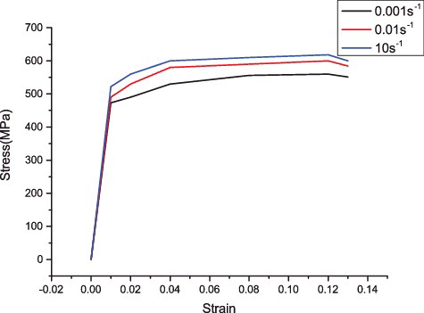
The stress–strain curves of aluminium alloy are plotted in . The largest strain rate considered in the present low-speed collision is less than 10 s−1, and therefore the stress--strain relationship applied in simulation is suitable.
Figure 5. The true stress--strain curves of 7075--T6 aluminium alloy with quasi-static, low and medium strain rates. The strain rates corresponding to the curves are 0.001, 0.01 and 10 s−1, respectively.
3.2. The impact of height
The impact of height on the mechanical property of crash box is first investigated. In the numerical experiment, three cellular models designed by uniformly sized auxetic cells with different heights are investigated. The heights of the cells are different from each other and other parameters such as the width and thickness are the same. The total width and length are 150 mm for all the three models, and the total heights are 100, 122 and 148 mm, respectively. The collision is simulated by putting a rigid plate with 4.17 m/s constant velocity vertically towards the structure. The mass of the plate is 0.5 tonne. The calculated time period lasts 0.1 s. The models of the crash boxes with different heights and the simulation results are shown in . The same material as presented in Section 3.1 is applied. Beam elements are used in the simulation.
Figure 6. Three models designed by uniform cells with different heights and their performances under constant velocity collision. The width of the models are the same. The figures in the first column show the planar view of the model, and the second and third columns show the middle and final stages of the deformation process.
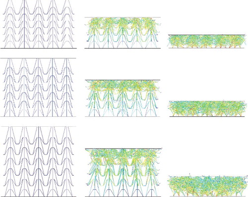
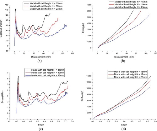
shows the performance of models designed by uniform cells with different heights. The resultant stress is calculated as the resistant force per area of the cellular box and the resultant strain is the ratio between the deformation of the upper side of cellular and the total height. Conclusions can be made from the result that when the height decreases, the energy density absorbed by per mass of the structure increases. This increasing is the property needed for the design of energy-absorption material. However, the resistant stresses, on the other hand, are also increasing. To design an ideal energy-dissipating structure, the energy absorption of per mass should be as large as possible and the resistant stress should be as small as possible. Clearly, these two requirements put out conflicting demands to the structure. With uniform sizes, larger height cells have smaller resistant force, but also with smaller energy absorption ability. To make most use of the cell, gradient design by combining the cells with different heights is an inevitable choice.
Figure 7. The performances of uniform models with different heights under constant velocity crash. (a) Displacement-- reaction force curve; (b) displacement--absorbed energy curve; (c) strain--stress curve; (d) strain--SEA (specific energy absorption) curve.
3.3. Analysis of typical design patterns
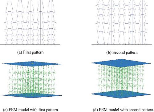
Two typical cellular structures with gradient cells are tested to explore the influence of gradient design on the energy-absorption performance. In the first design, the height gradually decreases from top to lower layers, and in the second type, the height increases, which are noted as model A and model B separately. The height of the first layer in model A is the same as that in the lowest layer in model B. a is denoted as the gradient coefficient, which means the ratio of the heights H between two adjacent layers. The gradient coefficient a is set as 0.8 and 1.25 separately. Each box is composed of six layers with five unit cells on each side of the layer, as shown in . Therefore, these two models are different from each other only for the arrangements of the layers.
Figure 8. Two models with different pattern in arranging gradient cells. (a) First pattern with gradually decreasing heights from top to bottom. (b) Second pattern with gradually increasing heights from top to bottom. (c) Finite element model of structure with first pattern. (d) Finite element model of structure with second pattern.
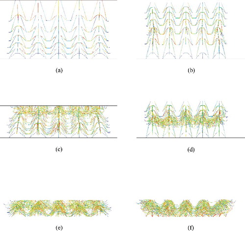
The free-style crash of rigid wall on the boxes is simulated. Different from the constant velocity crash used in Section 3.2, the free-style crash puts the same amount of crash energy on the cellular boxes and the velocity of rigid wall gradually decreases during the crush process. The bottom of the boxes is pinched and an initial velocity with mass is applied on the top to simulate the low-speed collision situation. The finite element models are shown in (c,d). The deformation process is plotted in . In both boxes, the deformation starts from the low-density area, and the deformation zone is gradually compressed and develops to a high-density area.
Figure 9. Deform schemes of the designed models with different manner in arranging the gradient cells. Each column shows different stages in the deformation process.
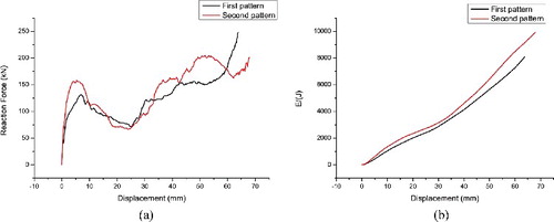
Analysis on the resistant forces provided by the two models are carried out. In both models, the same energy is absorbed by the boxes, and the reaction forces are also similar, as shown in . The largest reaction force is around 48 kN. These two patterns of organising cells have similar performance. Therefore, in the present design, we do not distinguish these two patterns.
Figure 10. Reaction force and energy absorption of the models with different manners in arranging the gradient cells in the crash process against the time.
4. Optimal design of cellular structure
4.1. Optimal design
In order to obtain the optimal design of gradient negative Poisson's ratio crash box, in this section, optimisation is conducted. Define length parameters as α = TL/L = TM/M, β = N/L, which are the thickness and length coefficients. The ratio of heights between adjacent layers are noted as a, which is set as constant within the model. With this design, the density is gradually changed. In the optimisation, TL is set as equal to TM. TL, N, the height ratio a, the height of the first layer H and the width W are chosen as design parameters in the optimisation. Parameterised model for the cell structure using these parameters is constructed. It is important to note that in order to meet the requirement that the structure has negative Poisson's ratio, the unit cell structure should always stay inside concave triangular shape in the process of changing parameters. The initial design is uniform density box with the cells in each layer designed to be the same. The objective is setting as minimum quality and largest absorbed energy in the constant velocity collision.
The constrains of design variables in the optimisation are set according to the needs of crash box. To make sure the cellular structure is manufacturable, for example, by addictive manufacturing, the thickness of the boxes must not be too small. Larger thickness ratio will lead to heavier model, so a upper limit is needed. In the design we set the thickness ratio as 0.035 ≤ α ≤ 0.15 and 0.15 ≤ β ≤ 0.3. To make sure the structure has negative Poisson's ratio, the cell must be concave. For this purpose, the constrains are set as 15 ≤ H ≤ 26, and 9 ≤ W ≤ 15. The height ratio is limited as 0.8 ≤ a ≤ 1.25. Six layers of cells are applied and the total height h ≤ 160 mm to make sure the structure is applicable as crush box.
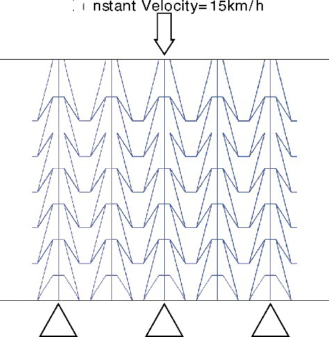
The model is simulated with finite element method. Low-speed collision situation is simulated. The constant impact velocity of 4.17 m/s is chosen, which is 15 km/h, as shown in . From the simulation, it is observed that the crash box absorbs most energy during the deformation stage. Then, in the densification stage, the absorption of energy is very limited. Therefore, in the simulation, the densification stage is omitted and the attention is focused on the deformation stage, with the impact distance chosen as 74% of the total height.
Figure 11. Simulation setting for the optimisation process. Constant impact velocity is used.
4.2. Optimisation results
Due to the reasons that the deformation of cellular structure during collision is complex and nonlinear material constitutive relations and contacts must be considered, the calculation of crush process generally is time-consuming. In order to improve the computational efficiency, the response surface function optimisation model is established. First, the optimal Latin super cubic method is used to select 40 sample points within the parameter space. Finite element simulation is carried out based on the chosen sample points. Then, third-order response surface function is established based on the simulation results. Finally, the NSGA-2 genetic optimisation is carried out to get the optimal design. In the response surface function, the quality variance is 0.9997 and energy variance is 0.9963, which make the established response surface function reliable. The obtained parameters are shown in .
Table 2. Comparison of optimised parameters of cellular structures with gradient and uniform cells. M represents the mass, E the absorbed energy, F the resistant force.
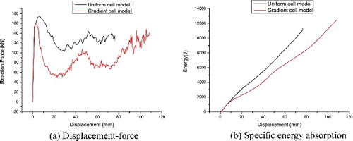
The optimised gradient cellular structure is shown in . For comparison, an optimised uniform cellular structure is used, which is calculated by setting the height ratio as constant one and the number of layers as a variable. The other settings in obtaining the uniform structure is the same as that in gradient one. Comparisons are made and the results prove that the gradient cellular structure has lower peak resistant force and also high energy-absorption ability than the uniform design, as shown in .
Figure 12. The geometry of optimised gradient model and original uniform model. (a) The optimised gradient model. (b) The optimised uniform model for comparison.
Figure 13. The comparison of the performance of optimised gradient and uniform cellular models. The gradient cellular structure has lower peak resistant force and also high energy-absorption ability than the uniform design. (a) The displacement--force curve. (b) Specific energy absorption.
5. Validations
5.1. RCAR standard test
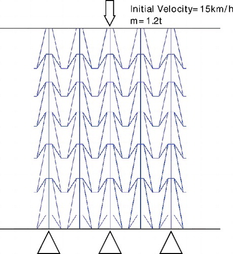
RCAR (Research Council for Automobile Repairs) standard test is conducted to show the effectiveness of the designed model. A given mass with quality of 1.2 tonnes with a speed of 15 km/h is applied on the top of crash box. The simulation model is shown in .
Figure 14. The RCAR test model of a given mass crashing into the cellular structure.
The resultant collision force--time curve is shown in . Through simulation, the largest collision reaction force is obtained as 169.7 kN, which is less than the threshold value of 180 kN. The result shows that the present model passes the RCAR standard test.
Figure 15. Force--displacement curve and specific energy absorption of crash box in RCAR test.
5.2. RCAR standard bumper test
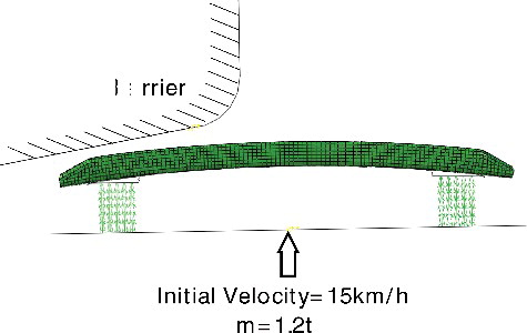
The crash box is applied within a bumper model to test its performance under collision. The calculation model is shown in . The contact between rigid wall, the bumper and also crash box is described by surface-to-surface contact model. The inner contact of crash box and bumper is simulated by general contact model. The rigid wall's mass is 1.2 tonne with an initial velocity 15 km/h. The simulated time period of collision lasts 0.16 s.
Figure 16. The model for RACR standard bumper test with the proposed gradient cellular structure as crush box.
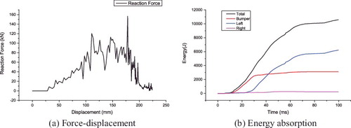
The deformation mode is shown in . Through calculation, the energy-absorption curve is obtained, as shown in . The bumper and the crash box absorb in total 7300 J energy, with maximum reaction force as 120 kN, which is less than the threshold value 180 kN. The crash box absorbs most energy and helps the bumper to pass the test.
Figure 17. Different stages in the simulation. The bumper and crash box deform gradually and absorb energy.
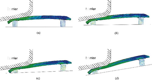
Figure 18. The left crash box absorbs 60% of the total energy and protects the bumper and the vehicle effectively. (a) The force--displacement curve of the bumper and crash box in the collision. (b) The amount of energy absorbed by the two crash boxes and the bumper bar.
6. Conclusions
In this paper, the gradient design is combined into negative Poisson's ratio structure and novel design of density gradient negative Poisson's ratio crash box is proposed. Optimisation of the structural parameters is conducted and the obtained design is verified by RCAR standard tests. Compared with uniform cell design, the present gradient model has lower reaction force and also better energy-absorption ability. The proposed gradient auxetic cellular structure provides an efficient design for the energy-dissipating structure.
Disclosure statement
No potential conflict of interest was reported by the authors.
Additional information
Funding
References
- A. Alderson and K. Alderson, Auxetic materials, Proc. Inst. Mech. Eng. Part G: J. Aerospace Eng. 221 (2007), pp. 565–575.
- W. Chen and T. Wierzbicki, Relative merits of single-cell, multi-cell and foam-filled thin-walled structures in energy absorption, Thin-Walled Struct. 39 (2001), pp. 287–306. doi:10.1016/S0263-8231(01)00006-4.
- M. Costas, D. Morin, M. Langseth, L. Romera, and J. DÃaz, Axial crushing of aluminum extrusions filled with PET foam and GFRP. An experimental investigation, Thin-Walled Struct. 99 (2016), pp. 45–57. doi:10.1016/j.tws.2015.11.003.
- K.E. Evans and A. Alderson, Auxetic materials: Functional materials and structures from lateral thinking!, Adv. Mater. 12 (2000), pp. 617–628.
- A.G. Hanssen, O.S. Hopperstad, and M. Langseth, Design of aluminium foam-filled crash boxes of square and circular cross-sections, Int. J. Crashworthiness 6 (2001), pp. 177–188. doi:10.1533/cras.2001.0171.
- S. Hou, Q. Li, S. Long, X. Yang, and W. Li, Crashworthiness design for foam filled thin-wall structures, Mater. Des. 30 (2009), pp. 2024–2032. doi:10.1016/j.matdes.2008.08.044.
- H.-S. Kim, New extruded multi-cell aluminum profile for maximum crash energy absorption and weight efficiency, Thin-Walled Struct. 40 (2002), pp. 311–327. doi:10.1016/S0263-8231(01)00069-6.
- R. Lakes, Foam structures with a negative Poisson's ratio, Science. 235 (1987), pp. 1038–1040. doi:10.1126/science.235.4792.1038.
- Y. Liu, Optimum design of straight thin-walled box section beams for crashworthiness analysis, Finite Elem. Anal. Des. 44 (2008), pp. 139–147. doi:10.1016/j.finel.2007.11.003.
- O. Mohammadiha, H. Beheshti, and F.H. Aboutalebi, Multi-objective optimisation of functionally graded honeycomb filled crash boxes under oblique impact loading, Int. J. Crashworthiness 20 (2015), pp. 44–59. doi:10.1080/13588265.2014.970398.
- Y. Prawoto, Seeing auxetic materials from the mechanics point of view: A structural review on the negative Poissons ratio, Comput. Mater. Sci. 58 (2012), pp. 140–153.
- A. Reyes, O.S. Hopperstad, and M. Langseth, Aluminum foam-filled extrusions subjected to oblique loading: Experimental and numerical study, Int. J. Solids Struct. 41 (2004), pp. 1645–1675. doi:10.1016/j.ijsolstr.2003.09.053.
- C. Schumacher, B. Bickel, J. Rys, S. Marschner, C. Daraio, and M. Gross, Microstructures to control elasticity in 3d printing, ACM Trans. Graph. 34 (2015), pp. 1–13. doi:10.1145/2766926.
- G. Srinath, A. Vadiraj, G. Balachandran, S.N. Sahu, and A.A. Gokhale, Characteristics of aluminium metal foam for automotive applications, Trans. Indian Inst. Metals 63 (2010), pp. 765–772. doi:10.1007/s12666-010-0117-7.
- G. Stephani, O. Andersen, H. Ghler, C. Kostmann, K. Kmmel, P. Quadbeck, M. Reinfried, T. Studnitzky, and U. Waag, Iron based cellular structures status and prospects, Adv. Eng. Mater. 8 (2006), pp. 847–852. doi:10.1002/adem.200600078.
- V. Tarigopula, M. Langseth, O.S. Hopperstad, and A.H. Clausen, Axial crushing of thin-walled high-strength steel sections, Int. J. Impact Eng. 32 (2006), pp. 847–882. doi:10.1016/j.ijimpeng.2005.07.010.
- Y.L. Wang, L.M. Wang, Z.D. Ma, and T. Wang, A negative Poisson's ratio suspension jounce bumper, Mater. Des. 103 (2016), pp. 90–99. doi:10.1016/j.matdes.2016.04.041.
- C.J. Xie, M.B. Tong, F. Liu, Z.G. Li, Y.Z. Guo, and X.C. Liu, Dynamic tests and constitutive model for 7075-t6 aluminum alloy, J. Vibr. Shock 33 (2014), pp. 110–125.
- W. Yang, Z.-M. Li, W. Shi, B.-H. Xie, and M.-B. Yang, Review on auxetic materials, J. Mater. Sci. 39 (2004), pp. 3269–3279.
- X. Zhang and G. Cheng, A comparative study of energy absorption characteristics of foam-filled and multi-cell square columns, Int. J. Impact Eng. 34 (2007), pp. 1739–1752. doi:10.1016/j.ijimpeng.2006.10.007.
- C. Zhang and A. Saigal, Crash behavior of a 3d s-shape space frame structure, J. Mater. Process. Technol. 191 (2007), pp. 256–259. doi:10.1016/j.jmatprotec.2007.03.093.
- W. Zhang, Z.D. Ma, and P. Hu, Mechanical properties of a cellular vehicle body structure with negative Poisson's ratio and enhanced strength, J. Reinforced Plastics Composites 33 (2014), pp. 342–349. doi:10.1177/0731684413510752.
- Y. Zhang, G. Sun, G. Li, Z. Luo, and Q. Li, Optimization of foam-filled bitubal structures for crashworthiness criteria, Mater. Des. 38 (2012), pp. 99–109. doi:10.1016/j.matdes.2012.01.028.