
Abstract
Purpose: To investigate the interaction of a robot assisted magnetically driven wireless capsule endoscope (WCE) with colonic tissue, as it traverses the colorectal bends in the dorsal and ventral directions, relying only on the feedback from a 3D accelerometer. We also investigate the impact of shell geometry and water insufflation on WCE locomotion.
Methods: A 3D printed incline phantom, lined with porcine colon, was used as the experimental platform, for controlled and repeatable results. The tilt angle of WCE was controlled to observe its influence on WCE locomotion. The phantom was placed underwater to observe the effects of water insufflation. The experiments were repeated using the two capsule shell geometries to observe the effect of shell geometry on WCE locomotion.
Results: Friction between WCE and intestinal tissue increased when the tilt angle of the WCE was lower than the angle of the incline of the phantom. Increasing the WCE tilt angle to match the angle of the incline reduced this friction. Water insufflation and elliptical capsule shell geometry reduced the friction further.
Conclusion: Tilting of the WCE equal to, or more than the angle of the incline improved the WCE locomotion. WCE locomotion was also improved by using elliptical capsule shell geometry and water insufflation.
Abbreviations: CRC: colorectal cancer; GI: gastrointestinal; MRI: magnetic resonance imaging; WCE: wireless capsule endoscope
Introduction
Colorectal cancer (CRC) is the second most common cause of cancer-related deaths worldwide. In 2018, over 1.8 million new cases were diagnosed and 0.88 million (9.2% of all the cancer-related deaths worldwide) were caused by CRC [Citation1].
Wireless capsule endoscopy has emerged as an alternative to flexible endoscope for small bowel screening. Orally administered, wireless capsule endoscopes (WCEs) pass through the gastrointestinal (GI) tract using gravity and peristaltic bowel movements and are primarily used for diagnosing small bowel diseases, where the lumen diameter is comparable to the diameter of the WCE. In the stomach and colon, WCEs flip around due to the larger lumen, potentially missing essential information [Citation2,Citation3]. In such cases, a WCE positioning system could improve the diagnostic yield.
Researchers have been investigating WCE positioning techniques since the early 2000s and the use of magnetic fields has been widely established as the preferred method [Citation4,Citation5]. This concept involves the interaction of a permanent magnet onboard the WCE (henceforth referred to as the actuator) with an external magnetic field (henceforth referred to as the manipulator) generated either by a permanent- or electro-magnet. This eliminates the need for onboard positioning mechanisms such as motors, replacing them with permanent magnet(s) and significantly reducing power consumption and complexity associated with WCE positioning systems onboard the capsule.
Among the various positioning techniques explored are spiral-shaped capsule shells [Citation6–7], MRI-style capsule control [Citation8], and handheld magnetic manipulators [Citation9], robot-assisted magnetic capsule endoscope (RAMCE) systems stand out as the most viable technique due to their performance, scalability, ease of use and cost effectiveness. RAMCE systems consist of a manipulator mounted on a robot and a capsule endoscope (wireless or tethered) embedded with permanent magnet(s), sensing and telemetry electronics. RAMCE systems rely heavily on sensor feedback (localization data) provided by the onboard capsule sensors, to control the movements of the capsule through the GI tract.
Two main categories of feedback are important for the RAMCE systems, i.e., capsule endoscope orientation and capsule endoscope spatial position (primarily, relative to the external magnet). Studies show that a capsule endoscope can be successfully controlled and positioned using these two feedback streams [Citation10]. Multiple techniques have been explored to implement such feedback. Inertial sensors such as accelerometers and inertial measurement units have been used individually and in combination with magnetic sensors to determine the position and posture of capsule endoscopes in RAMCE systems. Multiple hall sensors, both mono-axial and 3D, have also been used separately and in conjunction with inertial sensors to determine the position of the capsule endoscope. Although the use of magnetic sensors increases the accuracy of localization and improves the feedback, they result in a bulky external detector system and increase the electronics overhead that results in larger WCE size [Citation11–17].
As WCEs are intended for oral administration, there are strict size constraints. The average diameter of an adult’s esophagus can be distended up to 20 mm [Citation18]. Thus, any WCE passing through the esophagus needs to be at most 12 mm in diameter so that it doesn’t get stuck while swallowing, especially in the upper esophageal sphincter area. Even with state-of-the-art capsule endoscopes, patients can struggle swallowing such large pills.
Reducing the size of onboard electronics can shrink the WCE size. This is a cyclic process, i.e., fewer electronics components require lesser power, and thus smaller batteries can be used to power the WCE, which in turn reduces the WCE size. Sensing electronics for localization takes significant space onboard the WCE. Localization using fewer sensors can be used, by developing novel control and localization algorithms. Such algorithms rely heavily on the understanding of WCE-colon tissue interaction.
Colon anatomy has four key features that are relevant to the movement of WCEs. These include the tubular colon lumen, flexures and turns in the colon pathway, ventral or dorsal colon bends, and colon folds [Citation19]. This study aims at investigating the WCE interaction with ventral and dorsal colon bends (henceforth referred to as the colon incline). The WCE used in this study was part of a RAMCE system that employs a 3D accelerometer and a camera onboard the WCE to provide the localization feedback. The accelerometer is used to provide the angular posture of the WCE, and the camera is used to align the WCE with the colon lumen. However, as this is a study in progress, and the purpose of this paper is to investigate the interaction between the WCE and colon tissue to gain insights for WCE locomotion, the camera is not integrated into the WCE at this stage. A similar localization strategy has been explored by Ciuti et al. [Citation12]; however, they did not investigate the effects of colon incline on WCE locomotion.
WCE shell geometry plays a vital role in the positional stability of WCEs [Citation20]. The ideal shell geometry would be a sphere, from a frictional response perspective, as it only touches the intestinal tissue at one point. However, spherical geometry either complicates the electronics design and magnetic control or increases the capsule size due to reduced usable volume inside the shell [Citation21]. The authors thus reached a compromise with the elliptical geometry which was designed to be elliptical enough to display a significant effect on capsule locomotion compared to a cylindrical shell [Citation20]. This study extended the previous work conducted by the authors by using both the cylindrical and elliptical shells in all experiments performed. Performance of the different shell geometries was compared.
System architecture
RAMCE system used in this study has been developed by the authors and consists of a wireless capsule endoscope (henceforth referred to as capsule) and an external system. A key aspect of cancer screening techniques is their cost per test. The primary contributor to this is the manufacturing cost of the medical device used for screening. Electronic devices designed using commercially available components are cheaper than alternatives that use customized electronic components. The capsule used in this study was designed by the authors using commercially available components to minimize costs. The capsule was manufactured by Beta Layout (Aarbergen, Germany) and was assembled by the authors in-house.
Optimizing power consumption of the capsule electronics can reduce the required battery size. Power consumption in active electronic components is a function of several parameters such as the quiescent current, load current in various operating modes, clock frequency, and supply voltage [Citation22–24]. The authors carried out an exhaustive investigation of commercially available components based on the aforementioned parameters to select the most suitable components with low power consumption.
Modulation schemes used for data transmission also impact the power consumption of the transceiver. Based on previous work conducted by the authors, it was observed that gaussian frequency shift keying (GFSK) modulation scheme consumed low power and hence was selected for data transmission [Citation25].
The capsule architecture is modular and allows easy replacement of various modules. Multiple versions of circuit sections such as power management, sensing and processing, and telemetry, were designed using different core components. These modules were then tested iteratively to select the versions with optimum power performance for the given application. The capsule consists of
Three silver oxide coin batteries rated at 1.55V and 188mAh.
An axially polarized NdFeB/N52 permanent magnet (Volume = 230.4mm3).
A light switch that activates the capsule when high intensity white light is incident onto the capsule.
Power module PCB for regulating battery voltage, sensor module PCB hosting the accelerometer and microcontroller for capturing capsule angular posture and a radio module PCB hosting a transceiver operating at 433MHz.
Two capsule shell geometries (cylindrical and elliptical).
The capsule architecture is shown in , and the manufactured prototype placed in a half shell is shown in . The external system () consists of
Figure 1. Robot-assisted magnetic capsule endoscope system architecture used in this study. (A) 3D model depicting the modular capsule architecture, (B) assembled capsule prototype, (C) external system consisting of the robot, EPM, external camera, external receiver and the test bench, (D) elliptical capsule shell, (E) cylindrical capsule shell.
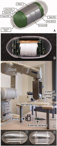
A six-degree of freedom (DOF) industrial robot (Mitsubishi RV-12S) on which a seventh DOF is implemented using a stepper motor to simplify the capsule actuation algorithms. The capsule is actuated by an NdFeB/N48 cylindrical external permanent magnet (EPM) (L = 80mm, d = 90mm) mounted on the robot. The robot and the stepper motor are connected to a PC via Ethernet and Serial Interface, respectively.
A transceiver operating at 433MHz, connected to the PC via a USB interface for receiving the capsule angular posture data.
A joystick for manipulating the robot.
A PC running control software developed by the authors which allows the robot manipulation with an accuracy of 1mm and 1° on all axes, receives data from the external receiver, determines the capsule angular posture, and calculates the new robot coordinates using the control algorithms discussed in this paper.
The angular posture of the capsule is determined by the onboard accelerometer using gravitational vectors as described in [Citation26]. The control software for the RAMCE system was developed by the authors using C# and the firmware running on the capsule in C. The RAMCE system operation consists of the following steps:
After activation, the capsule transmits its angular posture every 20ms.
The external receiver receives this data every 20ms, runs it through a control algorithm and produces appropriate robot coordinates for robot stabilization.
The control software reads the input from the joystick every 1ms. If the new input is different from the previous input, new robot coordinates are determined based on the updated input from the joystick.
Robot coordinates are transmitted every 10ms.
Capsule angular posture, robot coordinates, tilt, and yaw angles of the manipulator and other relevant data is logged into a file with a timestamp, every 20ms.
Material and methods
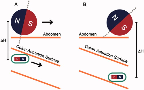
A simplified colon incline navigation scenario is shown in . The abdomen acts as a physical barrier which the manipulator cannot pass through. As the manipulator moves forward (), the distance between the capsule and the manipulator increases and the magnetic link weakens. When the magnetic force becomes lower than the weight of the capsule, the capsule loses contact with the anterior colonic surface (colon actuation surface). If the manipulator keeps moving forward, the capsule may not follow it, which could lead to a positional mismatch between the manipulator and the capsule.
Figure 2. Capsule interaction with colon incline. (A) Capsule maintains contact with colon actuation surface, (B) capsule loses contact with the actuation surface due to increased capsule-manipulator distance.
Ex-vivo experiments were conducted to study the capsule-tissue interaction as the capsule moves along colon inclines. Fresh porcine colon was used in all the experiments. As the dimensions of the porcine colon are different from those of a human colon, a 3D printed model (phantom) was used to simulate the dimensions of human anatomy. This biohybrid phantom, designed according to average dimensions reported by [Citation27], had holes throughout its structure, with the colon tissue sutured to it. The phantom, shown in , consisted of two sections, a straight and an inclined section with 20° inclination. shows the phantom dimension.
Figure 3. (A) Colon incline phantom with a straight and an inclined section at 20°, (B) phantom dimensions, (C) colon incline experimental setup using incline phantom lined with porcine colon.
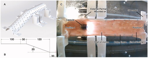
The porcine colon was attached to the phantom, which was then mounted on an acrylic plate platform. The capsule was placed inside the incline phantom, and the manipulator was positioned above it, as shown in . The capsule tilt angle was set at 0°. Afterwards, the manipulator was moved along the phantom from Position 1 to Position 2 and then backward from Position 2 to Position 1 (while tilt compensation [Citation20] was active so that the capsule maintains its tilt angle at 0°). The distance traversed by the capsule was recorded. Distance between the capsule and the manipulator (ΔH) was increased by an increment of 5 mm and the experiment was repeated until the magnetic force became lower than the weight of the capsule, and the capsule could no longer maintain contact with the phantom’s anterior surface. The experiment was subsequently repeated by tilting the capsule at increments of 5°, starting from 10° to 30°. To observe the influence of the capsule shell geometry, the capsule shell was changed from elliptical to cylindrical, and the aforementioned experiment was conducted again.
Studies show that water insufflation reduces peri- and post-colonoscopy pain (using a flexible endoscope), even in unsedated patients [Citation28,Citation29]. Water, like all fluids, is buoyant in nature. It exerts an upwards force to objects submerged in it, according to Archimedes Principle. The use of water also reduces the frictional forces experienced by the capsule. Keeping these facts in mind, it might be beneficial to use water insufflation to improve capsule locomotion in the colon. To investigate how water insufflation could improve capsule locomotion on inclined surfaces, all the experiments performed on the phantom were performed underwater.
Results
Performance of the colon incline navigation techniques was evaluated on the length of the phantom that was successfully traversed by the capsule across the full range of ΔH (5 mm to 70 mm). Three sets of experiments were performed to understand and improve capsule locomotion in the phantom shown in . Every experiment was repeated ten times and yielded similar results. Violin plots are used to depict the results in , indicating the distribution of the data (length of the phantom that was successfully traversed by the capsule) for various values of ΔH.
Figure 4. Colon incline navigation results. X-axis indicates the capsule tilt angle in degrees, left-handed Y-axis indicates the distance traversed by the capsule on the phantom in mm and right-handed Y-axis shows the ΔH trend. Navigation is improved by using elliptical capsule shell, tilting the capsule along the incline angle of the phantom, and by using water insufflation. (A) Results for cylindrical shell in air insufflated experiments. (B) Results for elliptical shell in air insufflated experiments. (C) Results for cylindrical shell in water insufflated experiments. (D) Results for elliptical shell in water insufflated experiments.
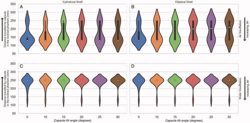
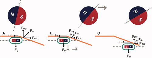
In the first experiment, the capsule traversed the phantom without any tilt. The capsule could traverse the complete phantom for ΔH <20 mm. It was observed that at ΔH = 20 mm, the capsule movement became erratic and could no longer follow the manipulator smoothly across the entire incline phantom. Upon reaching the start of the incline, the capsule would stop following the manipulator. As the manipulator moved forward, the capsule would momentarily drop and then get attracted by the manipulator again, moving forward along the phantom. This phenomenon is depicted in . However, upon increasing ΔH further, the capsule stopped moving when it encountered the “start of incline” as indicated in . These results are summarized in .
Figure 5. Capsule response to movement on the phantom. (A) Capsule encounters the start of incline, (B) manipulator moves forward, reducing the actuation force, (C) capsule drops and moves forward.
In the second set of experiments, the capsule was tilted as it traversed the phantom. It was observed that when the capsule tilt angle was equal to or greater than the incline angle of the phantom, the capsule could traverse the entire phantom over a wider range of ΔH. However, after ΔH = 45 mm, the capsule started exhibiting the same dropping and moving behavior depicted in . It was also observed that the elliptical capsule shell traversed the complete phantom over a wider range of ΔH values, outperforming the cylindrical shell. These results are summarized in .
The third set of experiments was performed underwater to simulate the effects of water insufflation. This resulted in significant performance improvement. It was observed that the capsule (both elliptical and cylindrical shells) traversed the complete incline phantom over a wider range of ΔH values of 5 mm to 55 mm, with a tilt of 0° and 5 mm to 60 mm, with a tilt of 20° or more. The elliptical shell performed slightly better than the cylindrical shell. These results are summarized in .
Discussion
The capsule proposed in this paper is intended to be trans-anally administered. However, this does not influence the findings of this study and the results are applicable to orally administered capsules as well. The authors are aware that this is a study in progress and certain aspects such as camera integration and positioning of the patient have not been explored. However, such topics are outside the scope of this paper (which focuses on understanding of capsule-tissue interaction, basic capsule locomotion using magnetic field, and effects of water insufflation) and will be explored in future works.
Ensuring a stable magnetic link between the capsule and the manipulator in a RAMCE system is of critical importance. Destabilization of this link can result in loss of capsule position and desynchronization of the capsule-robot sensor loop. This could lead to delays in navigating the capsule through the colon in the best-case or complete loss of capsule position in the worst-case scenario. As there are no magnetic sensors in the capsule that can measure the stability of the magnetic link (in this study), alternative methods are needed. This study focuses on maintaining a magnetic link between the manipulator and the capsule by aligning them physically. Hence, it is important to understand how the capsule follows the manipulator when it moves along colon inclines.
shows the interaction of the capsule with the phantom, depicting the erratic capsule movement and various forces affecting the capsule movement. In , the capsule and the manipulator are aligned, at the start of the incline. At this position, the frictional force (Fr) is lower than the x-component of the magnetic actuation force (Fmx). As the manipulator moves forward (), the magnetic actuation force is reduced due to the increased horizontal distance between the capsule and the manipulator, and the effect of friction becomes more dominant. As the manipulator moves forward, the capsule drops and loses contact with the colon tissue. This eliminates Fr and the capsule is then attracted again by the manipulator. This causes the capsule to move forward, as shown in . This process keeps repeating until ΔH is large enough that the actuation force exerted by the manipulator is less than the Fg and the capsule drops, losing contact with the anterior colonic tissue.
The erratic capsule movement descried above overexerts the tilt compensation [Citation20], and can result in missing visual information of diagnostic value. Tilting the capsule along the angle of the incline improves capsule locomotion because Fr is reduced. As results indicate, the capsule can traverse a longer distance along the phantom over a larger range of ΔH values.
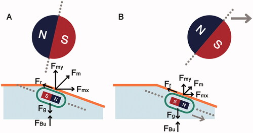
Water insufflation is an established technique used with capsules in RAMCE systems [Citation30]. However, its application in the colon has not been explored to date to the knowledge of the authors. This study indicates that water insufflation can significantly improve the capsule locomotion on inclined surfaces. The behavior of capsule locomotion (with a tilt angle) underwater is depicted in . In , the capsule, and the manipulator are vertically aligned. Here, Fm is the magnetic actuation force, Fr is the frictional resistance experienced by the capsule, Fg is the gravitational force, and FBu is the buoyant force exerted on the capsule. As the manipulator moves forward (), the capsule follows the manipulator along the incline because the water reduces frictional force experienced by the capsule, and the buoyant force lifts the capsule up (supporting the magnetic field).
Figure 6. Capsule interaction with colon incline using water insufflation. (A) Capsule encounters the start of incline, (B) capsule follows the manipulator along the inclined surface due to lower friction and buoyant support from water.
Results show that shell geometry influenced capsule locomotion. Elliptical shell geometry showed improved locomotion response compared to conventional cylindrical shell geometry. However, elliptical shell geometry has increased shell diameter as the uneven elliptical surface contributes to an increase in the overall capsule diameter. A combination of elliptical and cylindrical geometries could be used to reach a compromise between the shell diameter and capsule locomotion performance.
Conclusion
This study investigated the influence of colon incline on capsule locomotion in a RAMCE system. The capsule did not contain any magnetic sensors and relied only on a 3D accelerometer to establish a sensor-robot feedback loop. The authors used a 3D printed incline phantom lined with porcine colon, as an ex-vivo platform for controlled and repeatable experiments.
It was observed that the capsule locomotion is dependent on the actuation force exerted by the manipulator. As the distance between the manipulator and the capsule increased, the actuation force was reduced, hindering the capsule locomotion. This occurred due to the inherent friction of the colonic tissue, which becomes dominant when the actuation force diminishes. Tilting the capsule to match the angle of the incline helped improve the locomotion by aligning the capsule along the incline. Capsule-tissue friction was also reduced by using elliptical shells and water insufflation, which further improved the capsule locomotion.
Declaration of interest
The authors have no conflicts of interest.
References
- Cancer fact sheets: Colorectal cancer cancer. [Online]; [cited 2022 Jan 20]. Available from: http://gco.iarc.fr/today/fact-sheets-cancers?cancer=6&type=0&sex=0.
- Koulaouzidis A, Dabos K, Philipper M, et al. How should we do Colon capsule endoscopy reading: a practical guide. Ther Adv Gastrointest Endosc. 2021;14:1–15.
- Iakovidis D, Dimas G, Karargyris A, et al. Deep endoscopic visual measurements. IEEE J Biomed Health Inform. 2019;23(6):2211–2219.
- Sendoh M, Ishiyama K, Arai KI. Fabrication of magnetic actuator for use in a capsule endoscope. IEEE Trans Magn. 2003;39(5):3232–3234.
- Koulaouzidis A, Iakovidis D, Yung D, et al. Novel experimental and software methods for image reconstruction and localization in capsule endoscopy. Endosc Int Open. 2018;6:205–E210.
- Lee JS, Kim B, Hong YS. A flexible chain-based screw propeller for capsule endoscopes. Int J Precis Eng Manuf. 2009;10(4):27–34.
- Wang X, Meng MH, Chen X. A Locomotion mechanism with external magnetic guidance for active capsule endoscope. In 2010 Annual International Conference of the IEEE Engineering in Medicine and Biology; 2010. Buenos Aires: p. 4375–4378.
- Rey JF, Ogata H, Hosoe N, et al. Blinded nonrandomized comparative study of gastric examination with a magnetically guided capsule endoscope and standard videoendoscope. Gastrointest Endosc. 2012;75(2):373–391.
- Gu H, Zheng H, Cui X, et al. Maneuverability and safety of a magnetic-controlled capsule endoscopy system to examine the human Colon under real-time monitoring by colonoscopy: a pilot study (with video). Gastrointest Endosc. 2017;85(2):438–443.
- Bianchi F, Masaracchia A, Shojaei Barjuei E, et al. Localization strategies for robotic endoscopic capsules: a review. Expert Rev Med Devices. 2019;16(5):381–403.
- Arezzo A, Menciassi A, Valdastri P, et al. Experimental assessment of a novel robotically-driven endoscopic capsule compared to traditional colonoscopy. Dig Liver Dis. 2013;45(8):657–662.
- Ciuti G, Valdastri P, Menciassi A, et al. Robotic magnetic steering and locomotion of capsule endoscope for diagnostic and surgical endoluminal procedures. Robotica. 2010;28(2):199–207.
- Son D, Yim S, Sitti M. A 5D localization method for a magnetically manipulated untethered robot using a 2D array of hall-effect sensors. IEEE ASME Trans Mechatron. 2016;21(2):708–716.
- Salerno M, Mulana F, Rizzo R, et al. Magnetic and inertial sensor fusion for the localization of endoluminal diagnostic devices. Int J Comput Assist Radiol Surgery. 2012;7(S1):229–235.
- Salerno M, Ciuti G, Lucarini G, et al. A discrete-time localization method for capsule endoscopy based on on-board magnetic sensing. Meas Sci Technol. 2012;23(1):015701.
- Verra M, Firrincieli A, Chiurazzi M, et al. Robotic-assisted colonoscopy platform with a magnetically-actuated soft-tethered capsule. Cancers. 2020;12(9):2485.
- Valdastri P, Ciuti G, Verbeni A, et al. Magnetic air capsule robotic system: proof of concept of a novel approach for painless colonoscopy. Surg Endosc. 2012;26(5):1238–1246.
- Hirano I. Esophagus: anatomy and structural anomalies. In Yamada’s textbook of gastroenterology. Chichester (UK): Wiley; 2016. p. 42–43.
- Ciuti G, Skonieczna-Żydecka K, Marlicz W, et al. Frontiers of robotic colonoscopy: a comprehensive review of robotic colonoscopes and technologies. J Clin Med. 2020;9(6):1648.
- Mahmood S, Schurr M, Schostek S. Predictive tilt compensation for robot assisted magnetic capsule endoscope. In 41st annual international conference of the IEEE engineering in medicine and biology society (EMBC); 2019. Berlin: Germany. p. 3697–3702.
- Lucarini G, Ciuti G, Mura M, et al. A new concept for magnetic capsule colonoscopy based on an electromagnetic system. Int J Adv Robot Syst. 2015 Jan;12(3):134.
- Parsons D. Whitepaper 2: The Rules of Low Power MCU Design. [Online]. 2015; [cited 2021 May 03]. Available from: https://www.renesas.com/us/en/document/fly/whitepaper-2-rules-low-power-mcu-design?language=en.
- Parsons D. Whitepaper 4: Maximise Your Battery Life. [Online]. 2015; [cited 2021 May 03]. Available from: https://www.renesas.com/us/en/document/fly/whitepaper-4-maximise-your-battery-life.
- Ivey B. Microchip. [Online]. 2011; [cited 2021 May 03]. Available from: http://ww1.microchip.com/downloads/en/Appnotes/90001416a.pdf.
- Bose P, Khaleghi A, Mahmood S, et al. Evaluation of data telemetry for future leadless cardiac pacemaker. IEEE Access. 2019; 7:157933–157945.
- ST M. AN4509 Application Note: Tilt measurement using a low-g 3-axis accelerometer. 2014.
- Alazmani A, Hood A, Jayne D, et al. Quantitative assessment of colorectal morphology: implications for robotic colonoscopy. Med Eng Phys. 2016;38(2):148–154.
- Chaubal A, Pandey V, Patel R, et al. Difficult colonoscopy: air, carbon dioxide, or water insufflation? Intest Res. 2018;16(2):299–305.
- Radaelli F, Paggi S, Amato A, et al. Warm water infusion versus air insufflation for unsedated colonoscopy: a randomized, controlled trial. Gastrointest Endosc. 2010;72(4):701–709.
- Jiang X, Pan J, Li ZS, et al. Standardized examination procedure of magnetically controlled capsule endoscopy. VideoGIE. 2019;4(6):239–243.