Abstract
This paper deals with some structural properties for switching devices modelled by bond graphs. To calculate the structural rank of the state matrices, to point out impulse modes and to study the structural controllability and observability, graphical methods are proposed. These methods are based on simple causal paths and causal manipulations on the bond graph model.
1 Introduction
Switching devices are very common in several fields (diodes, relays, clutches, valves, …). Their changes of state can be either controlled or autonomous. Various researchers have investigated this problem using the bond graph tool [Citation1, Citation3 – Citation Citation Citation6, Citation8, Citation10, Citation12 – Citation Citation Citation15, Citation18, Citation20, Citation21]. Two main approaches, the ideal and the non-ideal ones, are recalled.
| a. | In the non-ideal approach [Citation6], switches are modeled as resistive elements what point out the loss of power in the ON mode eventually associated with a modulated transformer. The modulation is done using a Boolean variable. The main advantage of such an approach is that it leads to a unique causal bond graph model, no matters the state that switches can have. | ||||
| b. | In the ideal approach (no power dissipation) [Citation3, Citation20, Citation21], each switch is modelled by a null source: an effort source for a closed switch state, and a flow source for an open one. The state can be discontinuous at commutation times. This is the approach used in this work. | ||||
This paper is organized as follows: The second section recalls some useful background about bond graph modelling of switching devices. The modelling is done using the structure junction equation, leading to an implicit model E[xdot](t) = Ax(t) + Bu(t). In the third section, structural ranks of the E- and A-matrices are determined using causal manipulations on the bond graph model. This allows determination of the minimum number of input sources (respectively outputs) necessary for the control and optimisation of their positions to simplify state feedback control laws. In section 4, a procedure that allows an easy determination of impulse modes from a bond graph model is presented. This procedure is based on simple causal manipulations on the bond graph model. Graphical methods for structural R- controllability and structural impulse controllability are proposed in section 5. In the same way, in section 6, graphical methods for structural R-observability and structural impulse observability are proposed. Finally, section 7 gives an application example.
2 Modelling
In the ideal approach, all switched bond graph elements are classical bond graph elements with one exception, the switch. The switch is modelled as a null source; its type depends on its current state (flow source for an open switch, effort source for a closed one).
The junction structure of a bond graph model contains information on the types of elements which compose it and on the way they are interconnected. The different vectors involved in a bond graph are linked through the junction structure equation (Equationequation 1).
The switching law can be written as Equationequation (3).
Some hypotheses are taken into account.
| a. | Two dependent elements (I,C) in derivative causality are not directly causally connected, S 22 = 0. Actually, if this occurs, it is possible to change simultaneously their two causalities in order to obtain two dynamical elements in integral causality. | ||||
| b. | An element (I,C) in derivative causality is not causally connected to linear R- elements (otherwise it would be possible to exchange the causalities), S 23 = S 32 = 0. | ||||
| c. | The output is not directly connected to the input S 33 = 0. | ||||
| d. | No signal bond in the bond graph model is made. For sake of simplicity, we will suppose from now on that there are no algebraic loops between R-elements in the bond graph model studied. | ||||
2.1 State equation in the initial configuration
The initial configuration (or reference configuration [Citation3]) is chosen in order to maximize the number of elements in integral causality in the bond graph in preferred integral causality, denoted BGI. In this configuration (before commutation), Λ = 0 in Equationequation (3) implies Tin = 0, so Equationequation (4) can be rewritten as Equationequations (5) and Equation(6).
The output relation is given by Equationequation 7.
2.2 State equation in the configuration after the commutation
After the commutation Λ = I implies Tout = 0. From Equation(4) we obtain Equationeqution (8).
The output is given by Equationequation (9).
The expression for the sub-matrices composing E, A, and B proposed in Equationequation (8), is deduced from the junction structure matrix built from the bond graph model and elementary physical laws. For a 1-port bond graph model, the formal procedure to obtain these matrices directly from the bond graph is given in [Citation15].
Remark 1. It is important to note that a new model is obtained after each commutation. The dimensions of the vectors and the matrices are different. In this work, for sake of simplicity, we keep the same notations of dimensions and matrices before and after a commutation.
3 Structural ranks
In order to show how a bond graph model of a switching system is a good tool for structural analysis, we begin by studying the structural rank of the state matrix A denoted bg_rank [A] [Citation16].
3.1 Rank of A-matrix
The bond graph rank of the state matrix of switching systems is determined in the same way as for generalized systems [Citation14]. The difference here is that we have to consider two cases by switch, before and after its commutation.
Proposition 1
The bond graph rank of the state matrix A obtained in the initial configuration (respectively after the commutation) denoted by bg_rank [A] is equal to (ni – q) + nd, (respectively (ni – q) + nd + nw ) with q : the number of elements initially in integral causality staying in integral causality in the bond graph in preferred derivative causality, denoted BGD.
Proof
bg_rank[A] = N – q, with N = ni + nd (Equationequation (5)) or N = ni + nd + nw (Equationequation (7)). This proposition is equivalent to the one proposed in the case of model with neither elements in derivative causality nor switches (N = ni ) in the BGI [Citation22].
3.2 Rank of E-matrix
Proposition 2. The bond graph rank of the singular matrix E (noted r) obtained in the initial configuration (Equationequation (5)) is equal to ni , where ni is the number of dynamical elements in integral causality in the BGI.
Proof
Proof
After commutation, the bond graph rank of the E matrix is given by Equationequation (11).
4 Infinite mode
Let us consider the state model, described by the Equationequation (1), if the matrix [sE-A] is regular, output and input variables under null initial conditions (E x(0) = 0) are related by the non strictly proper transfer function, as Equationequation (12).
4.1 Algebraic characterisation
Using rank matrix conditions, the existence of infinite modes can be pointed out.
Proposition 4
In the initial configuration, the number of impulsive modes is null.
Proof
In this case d = n i and bg_rank[E] = ni , so r - d = 0.
Proposition 5
After the commutation, the number of impulsive modes is equal to
Proof
After the commutation d = ni and some elements change from integral causality to derivative causality.
| 1. | ⇒r = bg_rank[E] = ni + | ||||
| 2. |
| ||||
4.2 Graphical interpretation
A graphical interpretation of the number of impulse mode can be done using proposition 3 to calculate bg_rank[E] and [14] to determine the degree of the characteristic polynomial using the causal cycle families concept. The presence of infinite modes can be verified in the BGI in terms of causal paths. After the commutation, it can happen that some elements in integral causality lose their integral causality. Their number corresponds to the reduction of the order of the characteristic polynomial.
Proposition 6
The number of impulse modes is given by the number of elements that appear in derivative causality after the commutation in the BGI.
Proof
In the initial configuration d=n i. After the commutation, if p elements change to derivative causality, the number of elements in integral causality is then equal to n i −p. d=n i −p and bg_rank[E] = r is unchanged. Another equivalent proposition can be given as a graphical interpretation of
Proposition 7
The number of impulse modes is given by the number of disjoint causal paths which appear after commutation between elements in derivative causality and switch elements in the BGI.
Proof
In the same way bg_rank[E] = r is unchanged and thus it is equal to ni in the initial configuration and to ni +
Remark 2
Our purpose concerns only structural analysis, it is clear that for particular symbolic values of parameters the model can exhibit non structural impulse modes.
5 Structural controllability
The objective of this part is to present graphical methods using the bond graph methodology to derive information on structural controllability. For the switching system, the controllability property is decomposed into R-controllability, complete controllability and impulse controllability. Currently, we limit the study to the R-controllability and impulse controllability.
5.1 R-controllability
R-controllability is related to the ability to control the finite dynamic modes (classical controllability of exponential modes for regular system). It is associated with the differential part composing the state space.
Proposition 8
A switching system is structurally state R-controllable if and only if the two following conditions are verified:
| 1. | All (I,C) elements are causally connected with a source in the BGI. | ||||
| 2. |
| ||||
Proof:
This result is derived from digraph theory [Citation19].
The bond graph rank of the matrix [sE – A,B] is given using causal manipulations in the bond graph model.
Proposition 9
bg_rank[sE – A,B] = n − tc where tc is the number of dynamical elements remaining in integral causality when a dualisation of the maximal number of input sources is performed in the BGD in order to cancel these integral causalities.
Remark 3
The elements initially in derivative causality in the BGI keep their causalities unchanged in the BGD.
Proof
This result is a simple extension of the previous one, associated with regular model [Citation22].
5.2 Impulse controllability
Definition 1
A switched system is impulse controllable if all the impulsive modes can be excited by suitably chosen non-impulsive inputs.
Proposition 10
A switched system is impulse controllable if and only if:
Proof
Using the classical impulse controllability condition [Citation23].
A graphical interpretation of Equationequation (13) leads to the graphical interpretation of the impulse controllability.
Proposition 11
A switched system is impulse controllable if and only if the number of impulse modes is equal to the number of disjoint causal paths between input sources and switches passing through (I,C) elements in derivative causality in the BGI.
Proof
Using Equationequation (7), and the substitution of the E, A and B matrices,
Bg_rank
From Equationequation (13),
⇒ n + ni +
⇒ n + ni +
⇒
S 24 represents causal paths between (I,C) elements in derivative causality and switches elements, Bd is the input sub-matrix connecting input sources and (I,C) elements in derivative causality in the BGI,
On the other hand, we showed in section 4 that
6 Structural observability
Using duality with controllability, observability can also be decomposed into: R-observability, complete observability and impulse observability. The complete observability is not considered in this work.
6.1 R-observability
Definition 2
A switching system is R-observable if the initial condition x(0) can be determined by a given input control u(t) and a given output y(t).
Proposition 12
A switching system is structurally state R-observable if and only if the two following conditions are verified:
| 1. | All (I,C) elements are causally connected with a detector. | ||||
| 2. |
| ||||
Proof
This result is derived from digraph theory [Citation19].
The bond graph rank of the matrix
Proposition 13
Proof:
This result can be considered as an extension of the classical observability of regular systems modelled by bond graphs [Citation22].
Remark 4
The elements initially in derivative causality in the BGI keep their causalities unchanged in the BGD.
6.2 Impulse-observability
Definition 3
A switching system is impulse observable if at each time τ the knowledge of the output impulse and the input discontinuities at τ are sufficient to determine the discontinuities of the state vector x at the same time.
Proposition 14
A switching system is impulse observable if and only if:
Proof:
This result is the classical impulse observability condition [Citation23].
The graphical interpretation of this result is given using causal paths in the bond graph model.
Proposition 15
A switching system is structurally impulse observable if and only if, the number of impulse modes is equal to the number of disjoint causal paths between the switches and the output detectors passing through (I,C) elements in derivative causality in the BGI.
Proof
Using Equationequation (7) and the substitution of the E, A and C matrices,
⇒ n + ni +
⇒ n + ni +
⇒
S 24 represents causal paths between (I,C) elements in derivative causality and switches in the BGI, Cw is the output sub-matrix connecting switches and output detectors in the BGI,
7 Example
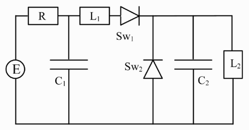
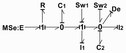
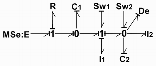
In order to illustrate the methods proposed for controllability and observability analysis, let us consider the simple example of the electrical circuit shown in . Sw1 and Sw2 represent diodes. The associated bond graph models represent the commutations.
Remark 5
The impulse controllability and impulse observability analysis is necessary only in the case that exhibits infinite modes.
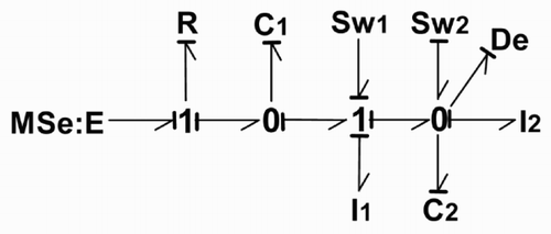
When Sw1 is closed and Sw2 open, the elements (I,C) are in integral causality. This configuration is chosen as the initial one (). If Sw1 is open and Sw2 closed, the second configuration () is obtained.
In the initial configuration : Sw1 closed and Sw2 open ()
| a. | All the elements are in integral causality, thus ni = 4 and nd = 0 = so n = ni + nd = 4. | ||||
| b. | The number of inputs sources is m = 1 and the number of outputs detectors is p = 1. | ||||
| c. | Bg_rank [E] = ni = 4. | ||||
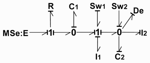
| d. | Bg_rank [A] : in the BGD all the (I,C) elements become in derivative causality (), so bg_rank [A] = n - q = 4. | ||||
| e. | R-controllability : in the BGI () all the (I,C) elements are causally connected to MSe and in the BGD () they become in derivative causality, so the model is R-controllable by the input E which has then to be a controlled input MSe. | ||||
| f. | R-observability : in the same way the model is R-observable by De. | ||||
In the configuration Sw1 open and Sw2 closed ()
| a. | In the BGI (), the number of elements in integral causality is ni = 2 and the number of elements in derivative causality is nd = 2. | ||||
| b. | The number of switching elements is nw = 2, so n = ni + nd + nw = 6. | ||||
| c. | The number of inputs sources is m = 1 and the number of outputs detectors is p = 1. | ||||
| d. | Bg_rank [E] : in the BGI (), the number of elements in integral causality is equal to 2, and there exits two disjoint causal paths between switches Sw and (I,C) elements in derivative causality ((Sw1, I1) and (Sw2, C2)), so r = 4. | ||||
| e. | Bg_rank [A] : in the BGD () the element I2 is in integral causality, q = 1, so bg_rank [A] = n − q = 5. | ||||
| f. | R-controllability and R-observability can be verified as in the initiale configuration. | ||||
| g. | Infinite mode: After the commutation two elements in derivative causality (I1 and C2) appear in the BGI (), so there exists 2 infinite modes. This result can be obtained by computing the number of disjoint causal paths between the switches Sw and (I,C) elements in derivative causality in the BGI. Here two disjoint causal paths appear ((Sw1, I1) and (Sw2, C2)). | ||||
| h. | Impulse controllability: the existence of two infinite modes implies that two input controls are necessary to control these impulse modes. In the BGI () m = 1, so this model is not impulse controllable. | ||||
| i. | Impulse observability: in the same way two output detectors are necessary to observe the two impulse modes. But in the BGI () p = 1, so this model is not impulse observable. | ||||
8 Conclusions
In this paper we have shown how the bond graph approach can be used as a good tool for structural analysis of switching devices modelled by bond graph. We have studied some graphical methods essentially for pointing out infinite modes and for structural analysis of controllability and observability. These methods are based exclusively on causality handling of the bond graph model. Simulation of the switching systems [Citation2,Citation8] is not considerd in this paper.
Our next work will concern the compensation of infinite modes. Actually, in the case where the model is impulse controllable, a static state feedback control can solve the problem, otherwise it is necessary to introduce a dynamic compensator. On the other hand switching systems are considerd as hybrid systems (see [Citation13] for example). Our objective is to propose some structural properties of hybrid systems modelled by bond graph.
References
References
- Asher GM Eslamdoost V Power electronic circuit simulation using bond graph technique pp. 807 – 812 Aachen EPE Congress
- Berlin , M , Diaz , G and Savage , G . 1985 . Simulation of ON/OFF Controlled Systems . Civ. ENgng. Syst , 2 : 155 – 165 .
- Buisson , J . 1993 . Analysis of switching devices with bond graphs . Journal of the Franklin Institute , 330 : 1165 – 1175 .
- Cellier FE Elmqvist H Otter M 1995 Modeling from physical principles, the control handbook Boca Raton CRC Press pp. 99 – 108
- Cormerais H Buisson J 1998 Toward a unified modeling of the continuous part of hybrid dynamical systems ADPM'98 19 – 20 mars, Reims
- Dauphin-Tanguy , G and Rombaut , C . 1989 . Why a unique causality in the elementary commutation cell bond graph model of a power electronics converter . IEEE/SMC'93 , 1 : 257 – 263 .
- Dion JM Commault C 1991 Feedback Decoupling of Structured Systems Grenoble European Control Conference
- Edström K 1999 Switched Bond Graphs: Simulation and Analysis Linköping Studies in Sciences and Technologies. Dissertations N°. 586, Linköping
- Glover K Silverman LM 1976 Characterization of Structural Controllability IEEE Trans. Aut. Cont
- Karnopp DC 1983 Alternative bond graph causal patterns and equations formulation for dynamics systems J. of Dyn. Syst., Meas., and Control ASME
- Lin , CT . 1974 . Structural controllability . IEEE Trans. Aut. Cont , AC-19 : 201 – 208 .
- Lorentz F 1993 Discontinuities in bond graphs : what is required? ICBGM'93, SCS Multiconference, San Diego
- Mosterman PJ 1977 Hybrid Dynamic Systems: a hybrid bond graph modelling paradigm and its application in diagnostic PhD thesis, Vanderbilt Univ
- Mouhri A Rahmani A Dauphin-Tanguy G 2000 Solvability and R-Controllability for Generalized Systems tate Modelled by Bond Graph 3rd MATHMOD pp. 733 – 738 Vienne
- Mouhri A 2000 Etude Structurelle des Systèmes Généralisés par Bond Graph PhD. Thesis, Univ. Lille
- Rahmani A 1993 Etude Structurelle des Systèmes Linéaires modélisés par Bond Graph PhD. Thesis, Univ. Lille
- Rahmani A Dauphin-Tanguy G 1998 Symbolic determination of state matrices from bond graph model In Proc. of Comput. Engineering in System Applications CESA
- Rahmani A Dauphin-Tanguy G 2003 Structural Controllability for Switching Systems Modelled by Bond Graph Mathmod, Vienne
- Reinschke KJ Wiedemann G 1997 Digraph characterization of structural controllability for linear descriptor Systems Linear Algebra and its Applications pp. 199 – 217
- Soderman U 1995 Conceptual Modeling of Mode Switching Physical Systems Linköping Studies in Sciences and Technologies N°. 375, Linköping
- Stromberg , J-E , Top , J and Soderman , U . 1993 . Variable causality in bond graphs caused by discrete effects . ICBGM'93 , 25 : 115 – 119 .
- Sueur , C and Dauphin-Tanguy , G . 1991 . Bond graph approach for structural analysis of MIMO linear systems . J. Franklin Inst , 328 : 55 – 70 .
- Yip , EL and Sincovec , RF . 1981 . Solvability, controllability, and observability of continuous descriptor systems . IEEE, Trans., Auto. Contr , 26 : 702 – 706 .
