Abstract
Bond graphs are primarily used in the network modeling of lumped parameter physical systems, but controller design with this graphical technique is relatively unexplored. It is shown that bond graphs can be used as a tool for certain model matching control designs. Some basic facts on the nonlinear model matching problem are recalled. The model matching problem is then associated with a particular disturbance decoupling problem, and it is demonstrated that bicausal assignment methods for bond graphs can be applied to solve the disturbance decoupling problem as to meet the model matching objective. The adopted bond graph approach is presented through a detailed example, which shows that the obtained controller induces port-Hamiltonian error dynamics. As a result, the closed loop system has an associated standard bond graph representation, thereby rendering energy shaping and damping injection possible from within a graphical context.
1. Introduction
Henry Paynter introduced the bond graph methodology in 1959, and this graphical modelling technique has proven to be a convenient framework for the network modelling of lumped parameter physical systems. Bond graph theory has developed rapidly over the years and a variety of standard textbooks are now available, and the reader is referred to the seminal book by Karnopp et al. Citation9 for a comprehensive treatment on bond graph modelling.
It can be safely argued that the modelling capabilities of bond graphs are well understood. However, bond graph tools in control are considerably less explored, of which some results can be found in Citation4, Citation8, Citation14 and references therein. The shortage of literature on bond graph based control has compelled us to contribute bond graph tools for certain model matching problems. Of course, the authors are aware that passivity-based methods form a vast field in control design, so our account should be viewed as just one possible application of passivity concepts in physical model based control.
This paper is organized as follows. Some essential on the nonlinear model matching problem (MMP) are addressed as detailed by Huijberts Citation7. Then it is recalled that the MMP can be associated with a disturbance decoupling problem (DDP), and to facilitate certain DDP solvability requirements the DDP is formulated in terms of virtual actuation concepts.
Bicausal bond graphs, as introduced by Gawthrop Citation2, are used to find the controls that solve the associated DDP. It is shown that the controller induces port-Hamiltonian error dynamics such that a standard bond graph representation of this dynamics becomes possible. Further stabilization is subsequently achieved through bond graph arguments. The reader is referred to Citation1, Citation5 and Citation13 for a comprehensive treatment on port-Hamiltonian systems.
To demonstrate the proposed methodology, a detailed example is presented. However, it was not attempted to derive a strict bond graph procedure for two main reasons. First, it is difficult to generalize in a nonlinear context, if not impossible. Second, the methodology considered here is based on the property that port-Hamiltonian error dynamics is induced by the controller, but it has not been verified whether this holds for general classes of bond graph models for which a particular MMP is solvable. Further research on this topic is required.
It is certainly the case that bicausal bond graphs are not new and that they are widely used for many applications but, the authors believe that the significance of this paper can be attributed to the explicit association of bicausal bond graphs with the DDP in the context of existing MMP theory. So, to the best of our knowledge, current applications of bicausal bond graphs in controller design have never been identified with the existing MMP theory as presented in Citation7 and references therein. The approach presented here could possibly spur or renew further research on bicausal bond graphs in physical model based control design.
2 Preliminaries
Consider the nonlinear plant of the form
Definition 2.1 (nonlinear model matching problem (MMP)).
Consider the plant P of the form
Equation(2.1) and the model M of the form Equation(2.2)
. The MMP is said to be locally solvable around (x
0, [xbar]
0) ∈ ℝ
n
× ℝ
[nbar]
if there exist controls u(t) such that the plant outputs y(t) follow the model outputs [ybar](t).
The above definition covers the essence of the MMP as described by Huijberts Citation7, in which two cases of the MMP are addressed: strong and weak model matching. The strong MMP has the control objective |y(t) − [ybar](t)| = 0 for all t ⩾ 0 whereas the weak MMP aims at the convergence property |y(t) − [ybar](t)| → 0 as t → ∞. Note that |·| denotes the usual Euclidean norm. It can be said that strong model matching is achieved through proper controller initialisation, but this could be difficult to achieve in real applications. The weak MMP will therefore be considered in the following developments only.
The MMP for P and M can be solved by solving its associated DDP Citation6. To this end one considers the extended system E = P × M defined as
Theorem 2.2.
Consider the nonlinear plant P and the nonlinear model M. Let the point (x 0, [xbar] 0) ∈ ℝ n × ℝ [nbar] be given. The MMP is locally solvable around (x 0, [xbar] 0) if and only if the non-regular dynamic disturbance decoupling with disturbance measurement is locally solvable around (x 0, [xbar] 0).
The solvability requirements of various disturbance decoupling problems can be stated in terms of maximally controlled invariant distributions or algorithms Citation7. These solvability requirements are not elaborated here. However, for the DDP considered in this paper, it generally suffices to require that relative degrees of model inputs ū are not strictly less than the plant inputs u with respect to the output y e (x e ). This requirement allows the disturbances ū to be “intercepted” by the controls u in many cases.
3 Setting up the nonlinear model matching problem
This section defines a particular form of the MPP through the use of virtual actuator concepts in a physical model based context. It is not attempted to derive a strict bond graph approach, but a more heuristic approach is taken instead to retain flexibility in the design.
It is shown that bicausal bond graphs Citation2 can be used to solve the associated DDP by effectively inverting the plant such that controls for disturbance decoupling are readily found.
3.1 Defining the plant bond graph
To give physical structure to the general MMP as described earlier, the systems of both the plant
Equation(2.1) and model Equation(2.2)
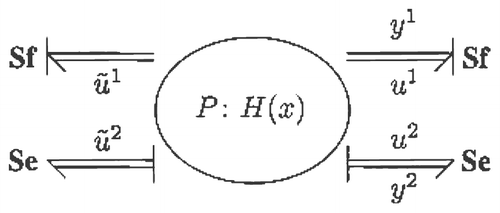
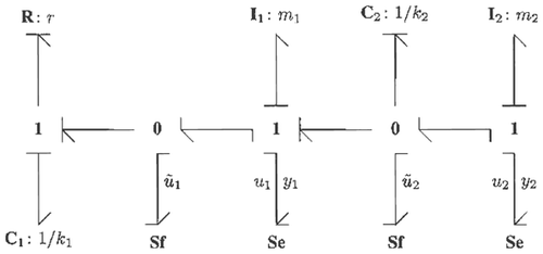
are specified with bond graphs. To this end, a vector bond graph for P depicted in
is considered. The inputs and outputs are defined as
The conjugate outputs of ũ 1 and ũ 2, will not play any role in the MMP considered here and have therefore been ignored. However, ignoring these outputs will lead to a plant P that is not port-Hamiltonian. Since standard bond graphs of which all conjugate input and output variables of source elements are taken into account belong to a class of port-Hamiltonian systems Citation5. Nonetheless, it will be shown that ignoring these outputs does not pose problems in the context of the paper, because the main objective is to have port-Hamiltonian error dynamics that allows for a standard bond graph representation. This will become clear in the sequel.
3.2 Defining the model bond graph
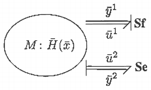
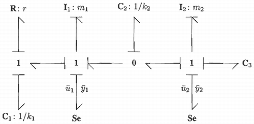
Next consider the bond graph model of M depicted in , where the pairs ([ubar] 1, [ybar] 1) and ([ubar] 2, [ybar] 2) are defined as
Let the bond graph of M be identical to P but without the ũ
1 and ũ
2 inputs. This is possible because of
Equation(3.1) and Equation(3.2)
. The desired behaviour of y is then obtained by adding bond graph components to M, where the MMP will ensure that y converges to [ytilde], if solvable. The additive components of M therefore act as virtual actuators that specify desired behaviour for the plant outputs y.
3.3 Setting up the DDP
Now that the bond graphs of P and M have been defined, the extended system
Equation(2.3) is readily obtained. To do this, first collect the input and output variables as
In view of
Equation(2.3), the MPP can now be associated with a DDP by considering the extended system
3.4 Solving the DDP and MMP
In Citation7 various procedures for solving DDPs are addressed but these will not be re-called here. Nonetheless, it can be argued that many of these procedures have great similarities with feedback linearization schemes for the extended system
Equation(2.3) of which the disturbances ū do not have relative degrees strictly less than the relative degrees of the controls u.
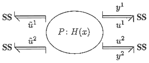
The above consideration will proof to be quite effective in the context of the paper. First the plant is inverted as depicted in where the relations y = [ybar] are subsequently enforced. Because inputs ū are treated as measurable disturbances, it will be shown that the relations u 1 = ū 1 and u 2 = ū 2 follow to decouple ū. The controls ũ 1and ũ 2 provide the remaining solutions to the DDP.
It is emphasized that solvability of the DDP considered here cannot be guaranteed by merely inverting the plant as in . However, since M is structurally “close” to P implies that causal paths from [ybar] to ū are topologically similar to the causal paths from y to u. It therefore seems intuitive plausible that relative degree conditions are more likely to be satisfied in this case, but further research on DDP solvability in relation to bicausal bond graph models is needed.
The MMP can be solved once the model inputs have been decoupled, so that further control on the decoupled extended system yields the desired decaying behaviour of the extended output y e (x e ).
4 Example
This section demonstrates the application of bond graphs for the MMP as defined in Section 3. The example shows that bond graphs in combination with virtual actuation concepts can clarify certain physical model based control objectives.
4.1 A mechanical system
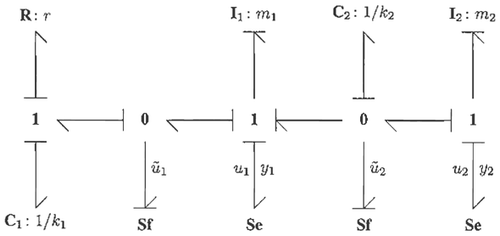
Consider the mechanical system depicted in of which the plant bond graph is depicted in .
The plant inputs u 1 and u 2 denote forces whereas model inputs ū 1 and ū 2 denote velocities. System outputs y 1 and y 2 are the respective velocities of masses m 1 and m. Parameters k 1 and k 2 are spring stiffness constants, and r is the damping coefficient.
It could be desirable to specify desired port behaviour for (u 1, y 1) and (u 2, y 2) in terms of a known physical system through control on ũ 1 and ũ 2. As a result, the control problem tends to be more physically motivated, thereby making the case for physical model based controllers and their possible significance. Such an approach turns out to be possible for the MMP context of section 3.
To this end, let (x
1,…, x
4) be local co-ordinates on that correspond to the storage components C1
, C2
, I1
and I2
respectively. From the causal assignment it readily follows that the plant P takes the form
4.2 The model
Suppose that the port pairs (u 1, y 1) and (u 2, y 2) of P are to match the port pairs of some model M as defined in section 3.2. To do this, consider the model in and its associated bond graph in .
The main idea behind the MMP as applied to this example becomes evident by removing ũ 1 and ũ 2 from P such that M becomes equivalent to P once C3 of M has been removed. Hence, the C3 component is seen to virtually actuate P through the controls ũ 1 and ũ 2, which can be considered to be working in the background as to attain the desired port behaviour for (u 1, y 1) and (u 2, y 2).
Let ([xbar]
1,…, [xbar]
5) be local coordinates on that correspond to the C1
, C2
, I1
, I2
and C3
elements respectively, then standard causal analysis yields the system
4.3 Solving the DPP
The DDP is now solved in view of the bicausal bond graph arguments of section 3.4. There is no need to construct the extended system
Equation(3.6) explicitly since the feedback linearization scheme is applied to P only.
The inverse of P can be conveniently depicted and obtained from , which is an important step in the approach considered here.
The bond graph inversion of P is particularly instructive since the bicausal bond graph shows the existence of one-dimensional internal dynamics: The C 1 component retains its integral causality after bicausal assignment Citation3. From it readily follows that the inverse of P takes the form
The decoupling controller is found by enforcing the relation y = [ybar] such that the time derivatives of y in
Equation(4.5) are taken along trajectories of M. Doing so yields the decoupling controller
claim 4.1.
The controller
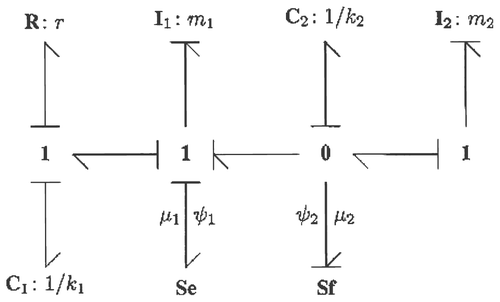
Equation(4.6) induces port-Hamiltonian error dynamics, allowing for a bond graph representation.
Proof.
By uniqueness and existence of trajectories, each state of the system
Equation(4.1) has an associated “error” variable
where
are reference signals. Consider the relations
Observe that
Equation(4.8) is port-Hamiltonian, so that there exists a bond graph representation Citation5. In addition, it is seen that the structure of Equation(4.8)
is close to Equation(4.1)
, so that Equation(4.8)
admits the bond graph of
.□
4.4 Solving the MMP
Now that the controller
Equation(4.6) has been found that solves the DDP, it remains to be shown how the extended output y
e
(x
e
) can be stabilised to zero.
Claim 4.2.
The equilibrium point e = 0 of
Equation(4.8) is globally asymptotically stable for μ = 0 such that the controller Equation(4.6)
solves the MMP.
Proof.
Let μ = 0 and write
Equation(4.8) as
Next consider the relation
The global asymptotic stability of the origin can now be established through a standard LaSalle argument Citation10. Let Z be a compact set containing the origin and let e(t) ∈ Z for all t ⩾ 0. In addition, define the set
Even though the controller
Equation(4.6) with μ = 0 yields a globally decaying extended output y
e
(x
e
), further control on μ is necessary to improve the response time consider the Se and Sf elements in
and replace them by linear R components, leading to the controls μ
1 = d
1
ψ
1 and μ
2 = d
2
ψ
2 for some positive damping constants d
1 and d
2. When this control is applied, the new dissipation rate becomes
To see how the energy can be shaped by using
, observe that μ
1 can be associated with the output of C1
whereas μ
2 can be associated with the output of I2
. Next consider the error dynamics
Equation(4.8) and its shaped Hamiltonian H
s
(e) defined as
5 Concluding remarks
Bicausal bond graphs were used to solve a physical model based disturbance decoupling problem. The inverted plant, in bicausal sense, was used to find those controls that decoupled the model inputs. This methodology was based on the simple requirement that the relative degrees of the model inputs should not be strictly less than the relative degrees of the plant inputs. It was seen that this relative degree condition was likely to be fulfilled in case the reference model was geometrically “close” to the plant. However, it was not attempted to derive general solvability requirements for the DDP considered in the paper, so that more research on bicausal bond graphs in relation to the DDP is required.
An important aspect of bicausal bond graphs, as applied in the paper, is that the inverse dynamics is required to remain stable for “arbitrary” model outputs that are to be tracked. This is not a shortcoming of bicausal bond graphs but an intrinsic problem when inverse systems are used for tracking control designs. Also, it is known that controllers based on inverse dynamics often lack certain robustness requirements. It is our intention to address internal stability and robustness issues of bond graph based controllers in future work.
Finally, it is important to note that the proposed bond graph methodology cannot be guaranteed to work at all times, mainly because the MMP setup was rather heuristic in nature, thereby retaining flexibility in case of unexpected difficulties. Nonetheless, the authors believe that the paper presented an instructive bond graph approach for physical model based control using passivity and model matching techniques.
References
- Dalsmo , M. and van der Schaft , A. J. 1998 . On representations and integrabilility of mathematical structures in energy-conserving physical systems . SIAM Journal on Control and Optimization , 37 : 54 – 91 .
- Gawthrop , P. J. 1995 . “Bicausal bond graphs” . In Proceedings of the International Conference On Bond Graph Modelling and Simulation (ICBGM'95), SCS Publishing , Edited by: Cellier , F. E. and Granda , J. J. 83 – 88 . US : Las Vegas .
- Gawthrop , P. J. 2000 . Physical interpretation of inverse dynamics using bicausal bond graphs . Journal of the Franklin Institute , 337 : 743 – 769 .
- P.J. , Gawthrop , D. , Ballance and D. , Vink . 2001 . “Bond graph based control with virtual actuators” . In Proceedings of the 13th European Simulation Symposium: Simulation in Industry , Edited by: Giambiasi , N. and Frydman , C. 813 – 817 . France : Marseille .
- Golo , G., , van der Schaft , A. , Breedveld , P. C. and Maschke , B. M. 2003 . “Hamiltonian formulation of bond graphs” . In Nonlinear and Hybrid Systems in Automotive Control , Edited by: Johansson , R. and Rantzer , A. 351 – 372 . London : Springer-Verlag .
- Huijberts , H. J.C. 1992 . A nonregular solution of the nonlinear dynamic disturbance decoupling problem with an application to a complete solution of the nonlinear model matching problem . SIAM Journal on Control and Optimization , 30 : 336 – 349 .
- Huijberts , H. J.C. 1994 . “Dynamic feedback in nonlinear synthesis problems” . In Centrum voor Wiskunde en Informatica (CWI) Amsterdam
- Sergio , J. 2001 . “Lyapunov Second Method and Feedback Stabilization Directly on Bond Graphs” . In International Conference on Bond Graph Modelling and Simulation (ICBGM'01), SCS Publishing , Edited by: Granda , J. J. and Dauphin-Tanguy , G. 137 – 142 . US : Phoenix . Volume 33 of Simulation Series
- Karnopp , D. C. , Margolis , D. and Rosenberg , R. 1990 . System dynamics, a unified approach, , 2nd edition , New York : Wiley .
- Khalil , H. K. 1996 . Nonlinear systems, , 2nd edition , New Jersey : Englewood Cliffs, Prentice Hall .
- Nijmeijer , H. and van der Schaft , A. J. 1990 . Nonlinear Dynamic Control Systems , New York : Springer-Verlag .
- Ortega , R. , Loria , A. , Nicklasson , P. J. and Sira-Ramirez , H. 1998 . Passivity – based control of Euler–Lagrange systems , Berlin : Springer-Verlag . Communications and Control Engineering
- van der Schaft , A. 2000 . L2-Gain and Passivity Techniques in Nonlinear Control , New York : Springer-Verlag .
- Yeh , T. -J. 2001 . “Backstepping Control in Physical Domains” . Journal of the Franklin Institute , 338 : 455 – 480 .
