Abstract
Research and development of advanced control systems to optimize the overall performance of parabolic trough collector (PTC) solar power plants is a priority line of research at the CIEMAT (Centro de Investigaciones Energéticas, Medioambientales y Tecnológicas - Research Centre for Energy, Environment and Technology). These developments are underway at the CIEMAT's Plataforma Solar de Almera (PSA), a highly specialized solar energy technology research centre. Some dynamic models for use in simulation and control of this type of solar power plant, developed in the PSA ACUREX facility, are presented in this article. The models developed are based on the ThermoFluid thermohydraulic modelling framework, in the Modelica modelling language. The ACUREX facility is presented with the main components modelled and their respective modelling assumptions. An operation strategy is presented and modelled based on the StateGraph Modelica library for discrete and reactive system modelling. A typical experiment is simulated with real experimental input data, a discrete operating strategy is designed and predicted model data are presented and discussed.
1. Introduction
This article presents the current status of research in the framework of modelling and simulation of parabolic trough collector (PTC) solar power plants. The work is mainly directed at the development of dynamic solar energy plant models to be used in the design of automatic control systems for optimizing overall performance.
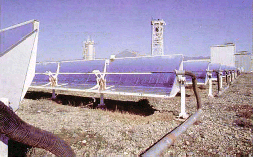
The test-bed plant is the ACUREX facility at the Plataforma Solar de Almería (PSA), a research centre belonging to the CIEMAT (Centro de Investigaciones Energéticas, Medioambientales y Tecnológicas - Research Centre for Energy, Environment and Technology), a dependency of the Spanish Ministry of Science and Innovation (see ). The present system consists mainly of a PTC solar field, a thermocline oil storage tank, an oil pump and an on–off valve. This facility is the experimental prototype of a commercial solar power plant scaled to 1 in which a wide range of experimentation can be performed.
The model presented in this article will be used in the design of hybrid model predictive control and intelligent control schemes to optimize plant performance, even under start-up and shutdown situations and in spite of highly variable load disturbances due to the daily cycle of solar radiation and passing clouds.
2. The ACUREX parabolic trough collector facility
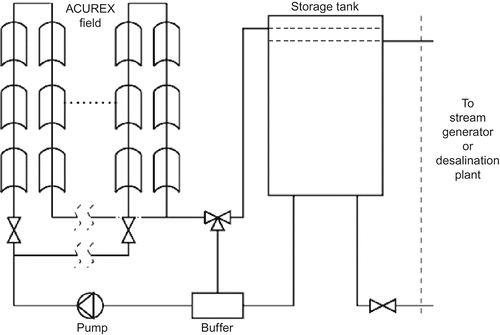
This section presents an overview of the basic components and operating procedures of the ACUREX plant. A schematic diagram is shown in , in which the most important components are depicted.
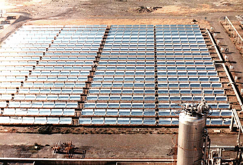
The ACUREX facility is made up mainly of four components,Footnote 1 the solar field, the tank, the oil pump and a three-way valve. The solar field is composed of 480 distributed solar collector modules arranged in 10 parallel rows. Each row contains four groups with 12 modules in each group, that is, 48 modules all of which work based on the concentration of incoming direct solar radiation onto the absorber tube located in the geometrical focal line of a parabolic trough reflector. As the sun position changes during the day, each PTC has to change its position with the solar radiation vector. The absorber tube in each PTC acts as an energy exchanger, receiving solar energy and transferring it to a thermohydraulic circuit with a heat transfer fluid (HTF) as the medium. Conventional PTCs use thermal oil as the HTF, and this is the case of the ACUREX field and current commercial plants. The HTF accumulates internal energy, and transports it to the tank. The total solar energy collecting surface is 2672 m2 and the collector axes are oriented East–West, with a 1° of freedom (elevation) solar tracking system. The heat transfer fluid is a commercial thermal oil which can be heated to 300°C without adverse effects on its thermal properties. shows the solar field arrangement.
The oil is stored in a 140-m3 thermal storage tank. The low-temperature oil (inlet) is pumped through a pipe (called the supply pipe) from the bottom of the tank to the field and delivered to the tank by a collecting pipe (called return pipe) at the top. The oil properties permit its energy storage to be stratified by density, allowing the use of a single thermocline tank for both hot and cold oil, with the hottest oil at the top of the tank. The stored energy is then transformed using a conversion system (not shown) which can be either a steam turbine for generating electricity or a desalination plant. The three-way valve allows the hot oil from the field outlet to be directed to the top or bottom of the tank. The oil pump controls the inlet oil mass flow rate into the field from the bottom of the tank.
The purpose of this plant is to supply regulated thermal energy to the demand process that is connected to the storage tank through a heat exchanger. This involves some other minor objectives, which must also be accomplished. One objective is an efficient control strategy ensuring that the field outlet temperature tracks the reference signal rejecting any disturbances (mainly solar radiation disturbances). The outlet field temperature is controlled by manipulating the oil flow pumped into the field. Another objective is automatic plant operation, including start-up, shutdowns or fossil-fuel burning as an auxiliary support energy source. There are constraints on both the manipulated variable as well as in the controlled variable. The oil flow rate can only be varied from 2 to 10 l/s, the maximum outlet oil temperature is 300°C and maximum temperature gradient in the field cannot exceed 80°C.
See [Citation1] for a comprehensive document describing state-of-the-art PTC technology.
3. Object-oriented modelling of ACUREX plant
This article concentrates on modelling the thermohydraulic part of the system, skipping the rest of the remaining subsystems (pneumatic, mechatronic, etc.) needed to maintain the proper instantaneous orientation of the PTC group, and assuming a known input radiation power in the absorber pipe, as a consequence of the radiation reflected in the parabolic trough mirrors. For a detailed explanation of these subsystems see [Citation1,Citation2].
Because of the fact that the main phenomenon of interest is the thermofluid dynamics, the Dymola tool [Citation3] was used to develop these models in the object-oriented Modelica language [Citation4]. The ThermoFluid library [Citation5,Citation6] is a framework in this modelling language with which own libraries and final component models, ready to be instantiated as simulation components, may be developed.
This article analyses each of the components in the thermohydraulic circuit and explains the modelling assumptions, justifying each as it is designed to find a DAE index system for the complete model that is not too high, and in which the number of non-linear algebraic loops is minimized by means of symbolic manipulation using the Dymola tool. All the components are therefore classified as control volumes (CV in ThermoFluid nomenclature) and flow models (FM in ThermoFluid nomenclature), following the modelling methodology derived from the finite volume method (FVM) [Citation7].
In some cases, information about the control system architecture to be implemented is introduced in the modelling phase. This methodology, from a strict point view, breaks up the work flow of the first main model and the design of the control system based on it. But it helps to simplify models' design and enhances the numerical behaviour of the whole modelled system in the simulation execution phase, without significant loss of accuracy.
As the internal implementation of some components may vary depending on the modelling hypotheses of the experimentation framework, polymorphism and the Modelica language constructs for classes and component parameterization have been extensively used and specifically applied in PTC models.
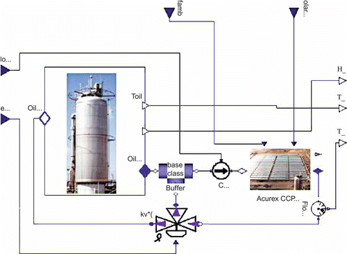
shows the top level Modelica model of the ACUREX facility developed, showing the tank, field, buffer and three-way valve.
3.1. ThermoFluid usage
The expected dynamic behaviour to be predicted by the models is mainly thermal, so the steady-state formulation for the momentum balance is selected for the ThermoFluid base classes used. The timescales selected for the thermal dynamics are for control design and simulation purposes.
The thermohydraulic interface for all the models is formed by connectors from the Interface package, for single component media and a steady-state momentum balance statement.
The modelling methodology adopted from the beginning for the design of the classes was that if there is any class in ThermoFluid that implements the physical phenomenon in the model, use it with the corresponding parameterization. If not, design the classes using inheritance from the high-level partial classes from ThermoFluid; in other cases, use proper ThermoFluid interfaces and base classes and develop the class lacking the behaviour expressed in differential and algebraic equations from first principles.
4. Subsystems models
In the following subsections, the most important component models are described and the modelling hypotheses are explained and justified.
4.1. Parabolic trough colectors solar field
The ACUREX PTC is the most important component in the facility. Indeed it is actually the component that gives the system and the facility their name. Its purpose is to focus most of the solar direct incident irradiance on the mirror onto the absorber tube. To achieve this, the manufacturing process employs advanced material sciences and technologies to minimize the power loss between the reflector and the absorber tube. References [Citation8,Citation1] analyse the energy flows from the sun to the absorber. On the other hand, this subsystem accumulates several uncertainties due to the age of some components, a factor that complicates modelling and simulation. To date, the model presented in [Citation9] has been extensively used for dynamic simulations and for control system design, giving very good results. To improve some modelling assumptions and benefit from the advantages of object-oriented modelling [Citation10], a family of polymorphic models have been developed, all of them sharing the same interface but with differing dynamic behaviour. This article describes one of the CIEMATE developments, but others, sharing the same interface are not described here because of confidentiality restrictions. This family of models includes the following modelling features:
-
Lumped and distributed parameter models.
-
Linear and nonlinear models.
-
With(out) delays, constant or variable.
-
Different first principles and experimental correlations for several physical phenomena.
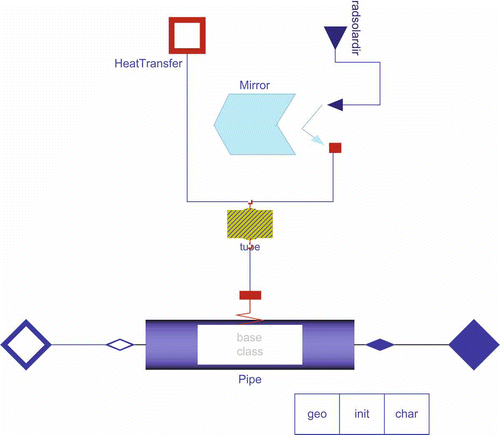
The main components of a PTC are shown in , and described below:
-
Parabolic trough reflector surface. This reflects the incoming direct solar radiation to the focal line of the mirror. The general equation type for this component is the
, where
and
are the incoming and reflected concentrated solar irradiation, respectively. The K gain is a function of several parameters or variables [Citation1].
-
Metal absorber pipe. It absorbs most of the energy reflected by the mirror. The energy balance equation if for a solid body:
, where
is modelled in the power loss component.
-
Energy loss rate
to the environment by conduction–convection and radiation. This is an algebraic relationship modelled from several correlations developed at CIEMAT.
-
Medium model, that is, of the HTF. In this study, the selected medium is Therminol55 (by Solutia) industrial oil now in used at the plant. An algebraic relationship between thermal properties and temperature is the core of this model.
-
Distributed CV, with a discretization level n in which mass ( EquationEquation (1)
(1)), energy ( EquationEquation (2)
(2)) and momentum ( EquationEquation (3)
(3)) are conserved. Mass and energy conservation are stated in a dynamic formulation, and the momentum (simplified) is in steady state with a staggered grid approach [Citation7,Citation5].
Where the variables in Equations (Equation1–3) are: M and E are the accumulated mass and energy in a CV, is the CV input mass flow rate,
the CV heat flow rate, p the pressure, V the volume, h specific enthalpy,
density, L length,
the friction factor, g the gravitational force and
the inclination.
For modelling purposes, this component could be considered a heat exchanger composed of one pipe with a heat transfer fluid as the medium, and a circular wall allowing thermal interaction with the fluid. This heat is fed by solar energy through the outer perimeter of the circular wall and, at the same time, some energy flow is leaving through this external perimeter by conduction–convection and radiation.
Thus the dynamic behaviour of each PTC will vary along each row depending on the thermodynamic and transport state of the thermal oil in each PTC. With the configuration shown in , the PTC is fully discretized in n CVs in the longest direction, in which mass, energy and momentum balances are stated. Momentum conservation is stated in staggered CVs with respect to those in which mass and energy balance is stated; see [Citation5,Citation7,Citation11]. The number of CVs, n, is a trade-off between accuracy and computing cost, so the final choice is the minimum n that models prevailing dynamics for control purposes. We are currently working with values in the [Citation2,Citation5] interval per PTC. The wall is discretized on the same discretization level.
To solve the PDE system stated from the balance equations, ThermoFluid provides partial classes [Citation5] in which discretization with the FVM [Citation7] is applied. One of these classes is Volume2PortDS-pT, which implements these mass, energy and stationary momentum conservation equations in a staggered grid formed by n subvolumes. For the solid media, there are final use classes that implement energy conservation in distributed solids (Walls).
To close the system of equations, the heat transfer coefficient must be entered between the bulk fluid flow and the solid media. This coefficient depends on heat transfer correlations using adimensional fluid numbers (Reynolds, Prandtl, Pecklet, . . . ), geometry of the contact surface and thermodynamic and transport properties of the fluid (i.e. oil ). Some of the correlation parameters strongly depend on the experimentation and parameter-adjusting phase of the modelling work. See [Citation12], which is entered by extensive use of Modelica partial polymorphic classes.
4.2. The storage tank
Like the other components the tank is modelled with several approaches that capture different dynamics:
-
Longitudinal gradient of temperatures in distributed parameter model.
-
Lumped parameter model of stored oil approximation.
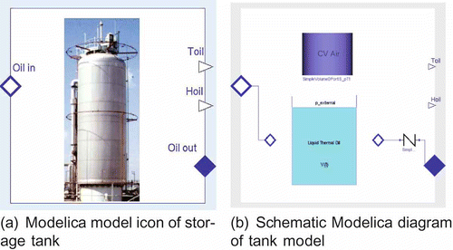
In all cases, the tank is pressurized with an inert gas above the oil. Mechanical interaction without mass/heat transfer between the oil and the gas volume is assumed and has been modelled as shown in the Modelica diagram with volume components in (a) and 6(b). Variable dimension CVs in which mass and energy conservation is stated have been developed.
4.3. Oil pump
For this kind of active FM [Citation5], we decided to simplify the assumption based on the experience gained in control of parabolic trough fields with a thermal oil medium, which is the case of PSA-CIEMAT ACUREX field [Citation9,Citation13–15
Citation
Citation15] and similar cases with other media like water-steam in the DISS facility [Citation1,Citation16]. The assumption is that the oil pump controlled in a cascade scheme [Citation17] by a local control loop with much faster dynamics than the rest of the thermohydraulic system. This is the current ACUREX field configuration, and has been experimentally validated in other facilities with blowers and water pumps. It is helpful to simplify these component models until it is possible to model them as steady-state quasi-ideal mass flow rate generators. This approximation avoids the time-consuming work of fitting the non-linear multivariate curves of the pumps and injectors. So, the algebraic equation for these components is , where
is the setpoint of the local pump/injector control loop assigned to the model in a connector, as can be seen in .
4.4. Three-way valve
This component, along the pump, is the second-most important actuator in the system. It directs the hot oil from the PTC field to the bottom or top of the tank, contributing to the generation of a vertical spatial temperature distribution inside the tank. Although it is modelled as a continuous actuator with saturation, it is used frequently as an on–off actuator.
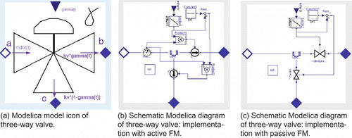
Again, object-oriented capabilities have been used intensively for valve modelling. For example, and active and passive flow model approach is presented, in which valves and dependent pumps are replaceable components. The concept is illustrated in .
4.5. Hybrid automatic operation-and-control system
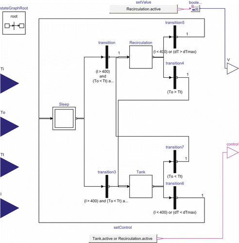
Although the ACUREX plant is usually operated manually by qualified human operators with excellent performance, the development of automatic operators was undertaken to make systems more autonomous. The Modelica StateGraph [Citation18] library was used to implement this model subsystem which includes the states and transitions for the whole operating during a typical operation day. In addition, this library offers features for defining suitable discrete event and reactive systems making Modelica an active language, and leaving the translator the responsibility of generating deterministic behaviour in the StateGraph. shows the operation-and-control component.
The operator model provides the following causal interface. Inputs:
-
Ti: solar field inlet oil temperature (°C)
-
To : solar field outlet oil temperature (°C)
-
Tt: mean tank oil temperature (°C)
-
I: solar irradianc (W/m2)
And outputs:
-
V: three-way valve with two positions:
-
1: solar field oil recirculation
-
2: oil from solar field to the tank
-
-
control: boolean signal that shows whether the solar field automatic control system must be activated (control algorithm not described here).
Then, the state machine component drives an experimental procedure for a typical operation day as explained below:
-
At the beginning of the day, the solar field is out of focus, with the pump off (Sleep mode).
-
When irradiance is over 400 W/m2, the system goes into one of the following two states when the control system is activated:
-
If Ti < Tt, then the system goes into Recirculation mode so the solar field is separated from the storage system.
-
If To > Tt, then the system goes into Tank mode and the water from the solar field flows to the storage system.
-
-
When the solar field temperature gain (To-Ti) exceeds dTmax (defined as a parameter), the system returns to Sleep mode. This also occurs when irradiance falls bellow 400 W/m2.
This module, in more complex versions, also includes the control algorithms.
5. Simulation of a typical operating cycle
This section describes simulation of one simple – but typical – real experiment. Solar irradiance measured at the PSA was used (see ).
Figure 9. Simulation results for filed outlet and inlet temperatures (To and Tt), for the inputs assigned in the graph above (solar irradiance and oil flow rate).
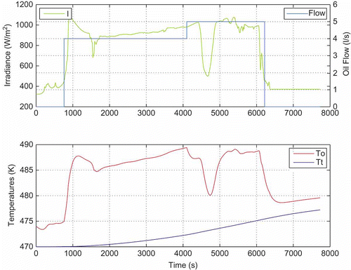
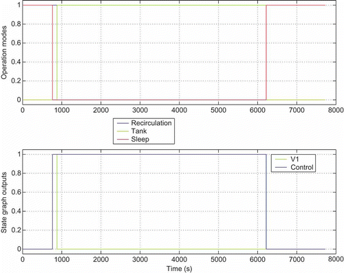
At the beginning of the day, solar irradiance is under the minimum defined for start-up. Therefore, the oil pump is off, the mode is Sleep (see ), and there is no oil flowing through the solar field.
When solar irradiance exceeds 450 W/m2, because the solar field outlet temperature is low (compared with the tank temperature), the mode changes to Recirculation so the storage system is separated from the solar field and the valve changes to position V1. Then, the oil pump is activated and the control output reports that the solar field control system must be activated.
After a little while, the mode changes to Tank. In this discrete state the tank is charged by the incoming thermal power from the solar-irradiated field.
Solar irradiance shows a drop in the middle of the simulation. Nevertheless, the outlet solar field temperature remains high enough to stay in Tank mode.
At the end, dense clouds produce solar irradiance under 400 W/m2, so the solar field goes back into Sleep mode and the oil pump is turned off.
If plant were actually operated as simulated in this section, the result would be irreversible damage to the plant from overheating the oil outside the permissible limits. This case clearly illustrates how dynamic models and automatic operation of the plant can be used to test operating strategies.
The simplified cycle modelled in this section is the basis for the development of optimal operating-and-control systems, which are further based on the accumulated heuristic knowledge of human operators during 25 years of experience at the Plataforma Solar de Almería (CIEMAT). This knowledge, combined with dynamic optimization techniques, leads to optimal automatic control systems for solar thermal power plants, which are tested in real time for operator support at this research centre.
6. Concluding remarks and ongoing work
This article shows the development of a dynamic model for the Plataforma Solar de Almería-CIEMAT's ACUREX facility, using object-oriented modelling. Most of the components are based on the ThermoFluid framework for thermohydraulic modelling, and the StateGraph library for discrete reactive system modelling. The main ACUREX components and simple operating principles have been described. For the main components, the modelling hypotheses and Modelica composition diagrams developed with the Dymola tool have been presented. References to the underlying physical phenomena have been made in these composition diagrams, describing them only briefly with differential and algebraic equations. Instead, the basic bibliography and the ThermoFluid/StateGraph classes that implement them have been referenced. Finally, a simulation of the system is executed with the boundary conditions of an actual experiment. Some results of the model simulation are shown.
Future work will refine the main models with more stringent parameter calibration, based on the actual plant experimental results. In this work, validation of empirical correlations for heat transfer and pressure loss and observed delay uncertainties will be important issues. In addition, implementation of heuristic knowledge acquired from experience in Acurex plant operation is another important work package.
The final aim is to develop automatic operation and control systems that would help this type of plant to operate in the most autonomous and optimal way, even in presence of strong disturbances. Automation of frequently obligated plant start-up and shutdown during the day is one of the main goals in this direction.
Acknowledgements
Funding by CIEMAT Research Centre, by the Spanish Ministry of Science and Innovation under Project DPI2007-66718-C04-04 and by the ERDF is gratefully acknowledged. This work was also done within the scope of a collaboration agreement between the Plataforma Solar de Almería-CIEMAT Automatic Control Group and the University of Almería (UAL) Automatic Control, Electronics and Robotics (TEP197) Research Group in the framework of the CIEMAT and UAL CIESOL Joint Research Centre agreement.
Notes
1. Other subsystems are not described for the sake of brevity.
References
- Zarza , E. La Generación Directa de Vapor con Colectores Cilindro-Parabólicos. El Proyecto DISS . ESII Sevilla, España.
- Zarza , E. Aplicaciones Industriales de los Colectores Cilindro-Parabólicos . Tech. Rep. R09/01EZ, CIEMAT-PSA, Crta. Senés s/n. 04200 Tabernas . 2001 . Almería, España
- A. Dynasim, Dymola 5.3 User Manual, Dynasim, A.B., 2004; software http://www.dynasim.se (http://www.dynasim.se)
- M. Association, Modelica, a Unified Object Oriented Language for Physical Systems Modeling. Language Specification 2.2, Modelica Association, 2005; software http://www.modelica.org (http://www.modelica.org)
- Tummescheit , H. 2002 . Design and Implementation of Object-Oriented Model Libraries using Modelica Ph. D. thesis, Department of Automatic Control, Lund Institute of Technology, Sweden
- Eborn , J. 2001 . On Model Libraries for Thermo-hydraulic Applications , Sweden : Department of Automatic Control, Lund Institute of Technology .
- Patankar , S. 1980 . Numerical Heat Transfer and Fluid Flow. Series in Computational and Physical Processes in Mechanics and Thermal Sciences , London : Taylor & Francis .
- González , L. , Zarza , E. and Yebra , L.J. Determinación del Modificador por ángulo de Incidencia de un colector solar LS-3, incluyendo las pérdidas geométricas por final de colector . Tech. Rep. DISS-SC-SF-29, CIEMAT-PSA . 2001 . Almería, España
- Camacho , E. , Berenguel , M. and Rubio , F. 1997 . Advanced Control of Solar Plants , Berlin : Springer-Verlag .
- Åström , K. , Elmqvist , H. and Mattsson , S. June 1998 . Evolution of Continuous-Time Modeling and Simulation , Edited by: Zobel , R. and Moeller , D. June , 9 – 18 . Manchester, , UK : Society for Computer Simulation International .
- Versteeg , H. and Malalasekera , W. 1995 . An Introduction to Computational Fluid Dynamics , Addison Wesley Longman Limited, Harlow, UK .
- Rohsenow , W. , Hartnett , J. and Cho , Y. 1998 . Handbook of Heat Transfer , Columbus, OH : McGraw-Hill .
- Berenguel , M. 1996 . Contribuciones al control de colectores solares distribuidos , España : Escuela Superior de Ingenieros Industriales de Sevilla .
- Camacho , E. , Rubio , F. , Berenguel , M. and Valenzuela , L. 2007 . A survey on control schemes for distributed solar collector fields. Part I: Modeling and basic control approaches . Solar Energy , 81 : 1240 – 1251 .
- Camacho , E.F. , Rubio , F.R. , Berenguel , M. and Valenzuela , L. 2007 . A survey on control schemes for distributed solar collector fields. Part II: Advanced control approaches . Solar Energy , 81 : 1252 – 1272 .
- Valenzuela , L. , Zarza , E. , Berenguel , M. and Camacho , E. 2004 . Direct steam generation in solar boilers . IEEE Control Sys. Mag. , 24 : 15 – 29 .
- Åström , K. and Wittenmark , B. 1997 . Computer-Controlled Systems , Upper Saddle River, NJ : Prentice Hall .
- Otter , M. , Årzén , K.E. and Dressler , I. StateGraph—A Modelica Library for Hierarchical State Machines . Proceedings of Modelica, Hamburg University of Technology . Hamburg-Harburg, Germany.
