Abstract
Molten carbonate fuel cells are a promising technology for the operation of future stationary power plants. To enhance service life, a detailed knowledge of their dynamical behaviour is essential. The possibility of fast and save load changes is important for daily operation of these power plants. To predict the dynamical behaviour of fuel cells a hierachy of mathematical models has been developed in the past. Recently a systematic model reduction was applied to a 2D crossflow model. We present here the new 1D counterflow model and discuss a suitable discretization method. Accordingly we set up a method of optimal control following the first-discretize-then-optimize approach. Results are shown for simulation and optimal control in the case of load changes.
1. Introduction
Stationary power plants working with molten carbonate fuel cells (MCFCs) are a promising technology for the near future. For an efficient operation a detailed knowledge of the dynamical behaviour is essential. Due to the possibility of irreparable damage of the real fuel cell during extreme operation modes, this detailed knowledge has to be provided (in part) by numerical simulations of (validated) mathematical models.
With combined effects from thermodynamics, gas dynamics, electrochemistry, heat diffusion and reaction kinetics, the modelling of high-temperature fuel cells gives rise to a multiphysics problem involving systems of coupled partial differential algebraic equations (PDAEs). Therefore, simulation-based optimal control of fuel cell models is a recent and challenging field of research. Further mathematical difficulties arise due to hyperbolic equations, non-local effects or state constraints (e.g. temperature should be bounded). For the latter we refer to [Citation1].
Hence it is recommended to develop new algorithms step by step on a hierarchy of models with increasing complexity. This article contributes a medium complexity model.
Based on a very detailed 2D mathematical model of the dynamical behaviour of a crossflow MCFC, we derive in this article a simplified 1D counterflow model. A suitable discretization method is explained that allows for detailed simulation results if load changes are to be carried out. From the results we gain useful information to set up an optimal control algorithm following the first-discretize-then-optimize approach. We present the algorithm and conclude with the optimization results.
2. New 1D counterflow model
We present a new 1D counterflow model of an MCFC using model reduction techniques analogously to [Citation2] and [Citation3], which is based on a 2D crossflow model described in detail in [Citation4]. The 2D crossflow model was developed by Heidebrecht [Citation5], see also [Citation6]. It was validated on a real power plant in [Citation7]. Both models describe an averaged single MCFC of a stack containing about 350 cells. The dynamic models describe the gas transport, the impact of the chemical reactions, the electrochemistry, as well as the heat convection and diffusion. All system variables are normalized and dimensionless; for details see [Citation5,Citation6].
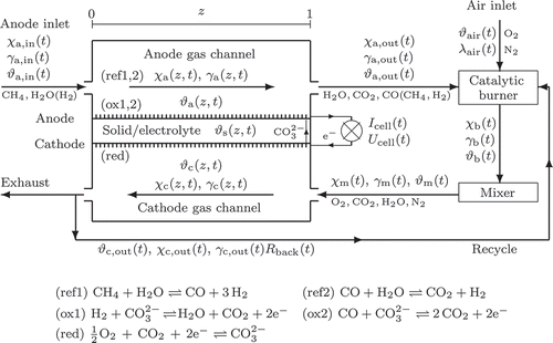
Figures 1 and 2 depict the variables of the new 1D model in the different compartments (a: anode gas channel with pores, c: cathode gas channel with pores. s, e: solid/electrolyte, b: catalytic burner, m: mixer). Spatial and time coordinate are denoted by .
The gas flow and the considered chemical reactions are depicted in A mix of methane and water is fed into the anode gas channel at (with optional hydrogen from external reforming). While the gas flows in positive
-direction, hydrogen is produced by internal reforming (ref1,2). A part of the gas diffuses into the pores of the anode sustaining the oxidation reactions (ox1,2). The anode gas outlet at
is connected with a catalytic burner, where the gas is completely oxidized with aeration to avoid material corrosion of the cathode electrode by CO [Citation6]. A mixer is attached to the burner outlet, whose modelling accounts for time delay and heat exchange with ambiance. Afterwards the gas enters the cathode gas channel at
, diffuses into the cathode electrode pores providing the reduction reaction (red) with oxygen and carbon dioxide. A part of the cathode exhaust gas is fed back to the catalytic burner to stabilize temperature (
).
Figure 1. 1D counterflow model of a molten carbonate fuel cell with variables vector of molar fractions,
,
,
,
and
3. Model equations
In [Citation5] the essential effects were modelled by PDAEs. We will now reduce those equations to a 1D model. Thus we rotate the cathode gas channel by 90° to obtain counterflow configuration and reduce to 1D. In the equations we have to take care of the spatial derivatives, the spatial integrals and the coupling variables. We obtain the following 1D model.
There are state variables on each layer. In the gas channels the system is described by the molar fractions and
for anode and cathode gas channels, respectively, for each of the seven species
occuring in the system. Furthermore, we have the gas temperatures
and the molar flow densities
. With assumptions from [Citation5], the gas dynamics is described by nonlinear reaction-advection equations
where the molar flow densities fulfil the degenerated partial differential equations
The source terms group into contributions from chemical reactions with reaction rates ,
, and into heat exchange densities with respect to neighbouring compartments
. These terms depend on state variables, see appendix A. All other terms, for example the Damköhler numbers
, are constants specified in Appendix B.
The temperature distribution in the solid is described by the semilinear heat equation
where the heat source depends on several states, cf. Appendix A. Compared to the 2D model we average the Péclet number of the two former space directions.
The fuel cell model is completed by a fourth compartment describing the catalytic burner and the mixer. The burner is fed with gas from anode and cathode outlet
and air inlet (,
,
). Its model is given by a set of scalar algebraic equations
where the right-hand side group into contributions from each of the three feeds. The mixer is then described by a system of differential algebraic equations (DAEs)
The current densities ,
,
,
and the currents
,
,
of the different layers (see ) are given by
Figure 2. Electrical potential field model, detailed view of the solid [Citation4], [Citation6], φ electrical potentials, i = current densities.
![Figure 2. Electrical potential field model, detailed view of the solid [Citation4], [Citation6], φ electrical potentials, i = current densities.](/cms/asset/ed98562e-f17f-4ee2-80d8-1d4e258a52ea/nmcm_a_642389_o_f0002g.gif)
The last three equations are the ordinary differential equations (ODEs) for the cell current and the degenerated PDEs for the potentials
and
at the anode and cathode ion layers, respectively.
The EquationEquations (1)1a
Equation(6)
1f form a nonlinear PDAE-system of mixed parabolic and hyperbolic type with integral terms (6d). The initial and boundary conditions are specified in Appendix C. The boundary conditions are coupled via the DAE-system of the burner and the mixer, which also contains a cycling of the cathode (i.e. the cathode outlet affects the cathode inlet). The system is autonomous and not explicitly dependent on the spatial variable z.
The cell current is an input parameter describing the load of the fuel cell; a load change is later modelled by a jump in the cell current. The technically realizable control variables are the temperature and the amount of air fed into the burner (
,
), the composition, temperature and amount of gas fed into the anode gas channel (
,
,
) and the amount of cathode gas refeeding (
).
We further reduce the model by a maximum elimination of species in the system: Due to non-participation in the gas feed and the chemical reactions and finally due to complete combustion in the catalytic burner we conclude
In a second step, we replace one further species in each gas compartment () by the linear algebraic equations
We end up with a reduced model containing 12 PDEs, a couple of ODEs and algebraic equations.
4. Discretization of the PDAE model
The results will later show that the fuel cell model (1)–(6) makes high demands on the time discretization. Besides, the spatial discretization needs special treatments due to the hyperbolic transport equations. Therefore, we suggest the method of lines and the use of an existing adaptive DAE-solver.
Thus we apply a semidiscretization in space on the equidistant grid
with step size
. The state variables depending on z (e.g.
) are approximated by
and so on.Footnote
1
Since the equations in the gas channels are hyperbolic transport equations (or degenerated transport equations), we apply well-known upwind schemes to ensure stability, for example one-sided difference quotients contrary to the flow direction. Due to a priori known constant flow directions in the gas channels, we apply forward difference quotients in anode and backward difference quotients in cathode. The underlying total and partial mass balances are discretized in this manner; reformulation of the discretized conservation laws in type of the molar fractions yields (cf. [Citation8])
for and analogous equations for the gas temperatures
. As we see, the upstream molar flow densities have to be used to fulfil the discrete conservation laws. At the inlets we insert the boundary conditions, for example
. The derivatives in (1e), (1f) result in
and
by direct discretization of the product.Footnote 2 The Laplacian is treated with the usual second-order difference quotient
The symmetry conditions enter at both boundaries by setting
The explicit algebraic equations (4a–4d, 5c–6e) are eliminated by substitution with the integrals in (6d) discretized by suitable quadrature formulas (e.g. composite trapezoidal rule). Both degenerated PDEs (6g, 6h) yield a set of N ODE. The semidiscretization results in a DAE system for the variables
, where
are the algebraic variables. The generalized mass matrix M is a constant singular diagonal matrix. The algebraic parts stemming from the idealized time constants in (1e), (1f) yield a semi-explicit DAE of index one [Citation10], moreover, the algebraic equations are linear in the algebraic variables. Thereby the semi-explicit DAE-system can be solved efficiently with standard solvers.
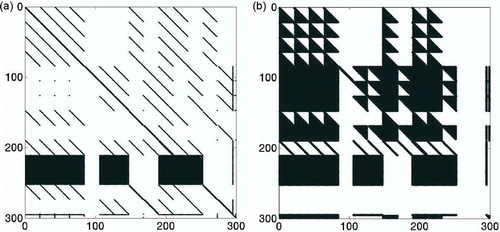
As expected from a semidiscretization of a heat equation, the DAE turns out to be stiff. Hence we rely on implicit methods to solve it. Numerical experiments show that fully implicit schemes have to be applied; standard semi-implicit schemes turn out to be unstable. As a consequence each time step involves the solution of a system of nonlinear equations. This is done with Newton-type methods, which need Jacobians. We provide the Jacobians either by Automatic Differentiation (AD) with the tool ADiMat [Citation11] or by standard numerical differentiation ()(odenumjac).
The Jacobian of f, (a) is sparse with some dense rows due to the integral terms in (6d). The plot in (b) belongs to an ODE-formulation, where the linear equations for ,
are eliminated (in case of
). We do not recommend the ODE-formulation, since the Jacobian is a lot more dense while its dimension is not significantly smaller (the empty rows and columns can be dropped). With an efficient DAE-solver at hand, we suggest to solve the system using the semi-explicit DAE-formulation.
Figure 3. Sparsity plot of the Jacobian of f: DAE (a) vs. ODE formulation (b).
It is very important to apply an adaptive time discretization since the PDAE-model possesses different time scales and shows high gradients directly after the load change, cf. Section 6. The adaptivity is achieved by ode15s.
The initial conditions of the algebraic variables are a crucial point in solving a DAE. The constant initial values in Appendix C are convenient only for coarse discretizations; for finer discretizations, the initial values for are computed by iterated computation of stationary solutions followed by interpolation on a finer grid.
5. Optimal control problem and method
The efficient operation of a fuel cell stack gives rise to an optimal control problem. Some state variables at the gas inlets should be adapted to minimize a certain objective that accounts for a long service life, a high efficiency or a reliable and accurate power generation. We model the objective J by one of the two variants
The first term penalizes the deviation of the cell voltage or the solid temperature from a desired state or
. The second term accounts for the control costs (e.g. the energy consumption due to heating of the gas flows) with constant positive cost factors
for the seven controlsFootnote
3
The controls are technically restricted to box constraints
The limits are constants, given in Appendix C. The molar fractions canonically cause state constraints
Since high temperatures or high temperature gradients of the solid parts lead to material corrosion [6], further state constraints should be taken into account:
Since state constraints complicate the solution of optimal control problems with PDAE-models, we avoid (20) and try to fulfil them approximately by suitable choice of desired states.
In addition the state constraints (19) are fulfilled automatically due to consistent initial and boundary conditions and consistent modelling of the right-hand side of the PDAE or DAE together with the elimination (7), (8). Hence the state constraints (19) are dropped in order to avoid possible degeneracy of the nonlinear programme (NLP).
The resulting control problem is treated with the first-discretize-then-optimize approach: The control and state variables are discretized and the objective is computed by a suitable quadrature formula, for example the rectangle sum. The resulting nonlinear programme is solved with fmincon in MATLAB. Since we are facing a boundary control problem, we prefer to work with the reduced optimization problem where the controls are the only optimization variables. Each function call then contains one solution of the PDAE according to Section 4 and the rectangle sums.
A suitable discretization of the controls is crucial for an efficient method. The numerical results will later show that neither piecewise constant controls nor a discretization on the time grid of the DAE-solver is appropriate. Instead, we suggest to use linear splines on a coarser control grid. Thereby we end up with a very limited number of optimization variables () but an expensive function evaluation with
state variables.
6. Results
We are interested in the dynamical behaviour of the MCFC in the case of a sudden load change modelled by a jump in the cell current
6.1. Simulation results
For test computations we set ,
,
and stationary controls
; cf. Appendix C. We solve the PDAE with 81 lines in space. The adaptive DAE-solver chooses 160 points in time. The CPU time is 10 sec with Matlab R2010b on an Intel64 3.3 GHz dual core with 8GB memory.
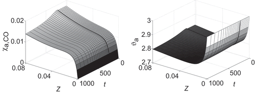
All distributed state variables show high gradients in time immediately after the load change and approach the new stationary value asymptotically, see The step heights rise througout the anode gas channel with a maximum in
; in contrast, the step heights decrease along the flux direction towards
in the cathode gas channel.
Figure 4. Load change at
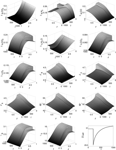
A detailed view of the transition region is depicted in We observe three different time scales: We have an extreme fast adaption of the molar flow rates and
within seconds. Also the electrical variables
adapt quickly. The molar fractions have medium reaction times. The
monotoneously adapt whereas the
show overshooting directly after the load change: This is due to delay times of the system: Especially the mixer is modelled by a delay element of first order, see (5a and 5b). The anode and solid temperature
show very smooth and slow transition. High spatial gradients are observed only at the anode inlet
and only in two state variables (see ).
Figure 5. Zoom in time: Load change at ;
at
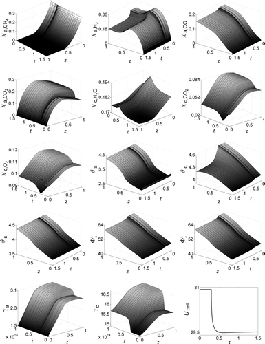
Figure 6. Spatial zoom on : Load Change at
.
In order to investigate the spatial discretization error we define the relative error of a state in
and
by
Since an error analysis for all 14 states would go beyond the scope of this paper, we ask for the maximum error defined by
and
. In (upper) we depict these relative errors of different spatial discretizations compared to the finest discretization with N = 641 lines and a fixed time discretization with 1000 time steps adaptively computed by ode15s for N = 641 lines. The coarsest space discretization starts with relative errors ρ2
6 of maximal 2%: The states are very smooth in space. Nevertheless, the accuracy increases with finer grids due to a better resolution of the high gradients in
Table 1. Maximal relative errors of the simulation for different discretizations. Upper part: Fixed adaptive time grid with 1000 time steps. Lower part: Fixed equidistant spatial grid with 641 lines
An analogeous investigation of the time discretization error ,
of a time discretization with m time steps in comparison to an adaptive time discretization with 4405 time steps and fixed spatial discretization with 641 lines is depicted in (lower). There are two series of time discretiations (adaptive and equidistant). The results show that an adaptive solution with 57 time steps is more accurate than a solution on an equidistant time grid with 1991 time steps, that is the adaptivity of the time discretization is essential for the computation of an accurate solution.
6.2. Optimal control results
For optimal control we set ,
,
lines,
and
. The time discretization is done adaptively (1000–1200 time steps). We aim for a fast load change, hence we choose the objective
and
with stationary voltages belonging to
for
. Due to the adaptive time grid and its very fine resolution at
, the NLP solver gets lost and starts oscillating with exploding discretization error if we allow to choose the controls on each time step independently. To avoid this stability problem, we restrict the controls to linear splines on a coarser equidistant control grid
,
with
.
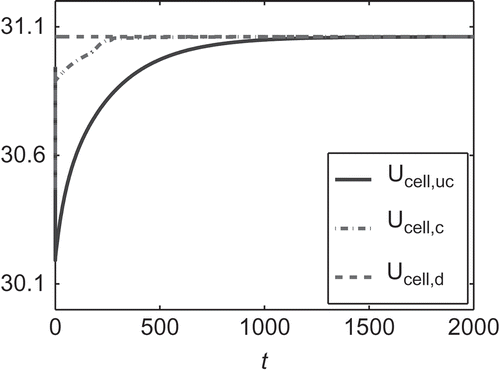
We choose the six controls (with
and
). The resulting optimal controls are shown in At the beginning all controls are active to reduce the jump in the cell voltage with maximum speed. When the desired state is within reach at
, more and more controls begin to vary in order to level out the cell voltage. shows the cell voltage of the controlled and uncontrolled fuel cell in comparison to the desired cell voltage
. The stationary state is reached in a fifth of the time that is needed without control. The objective is reduced from
to
.
Figure 7. Optimal controls for a load change at
.
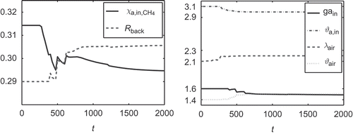
Figure 8.
with optimal control of
(c) and without control (uc) in comparison to
.
7. Conclusion
Fuel cell models raise many non-standard problems within the task of simulation-based optimization and optimal control. Therefore, methods of optimal control have to be enhanced and adapted to meet the demands given by applications.
In this article we have contributed a new 1D counterflow model to the hierarchy of MCFC models. We reduced the number of states to a minimum. This model enables the development of advanced mathematical methods of optimal control for PDAE systems.
Results show that the crucial discretization is the time discretization; thus we suggest to discretize with the method of lines and to apply sophisticated adaptive DAE-solvers. This yields accurate simulation results in fast computation times. In a second step we apply methods of nonlinear programming to the discretized PDAE model yielding approximate results of optimal control for the fuel cell system. The presented discretization and optimization methods are not restricted to the 1D model and can easily be extended to higher dimensional PDAE models. However, the computation times and memory requirements will increase significantly.
To cope with this, the combination of direct methods of optimal control with model reduction techniques (e.g. the POD method) and a suitable application of automatic differentiation will be part of future investigations. Besides, first order optimality conditions of the optimal control problem are investigated and solved by adjoint-based methods in [Citation12]. Moreover, a parametric sensitivity analysis of the optimal control results along the lines of [Citation13] is useful for practical implementation.
Acknowledgement
We are indebted to Dr.-Ing. Peter Heidebrecht and Dr. Kati Sternberg for providing us with the realistic 2D fuel cell models.
Notes
1. The tilde and the N are omitted below; we need it in Section 6.1 again.
2. First product rule and then difference quotient would yield which has to be done inside Easyfit [Citation9]. For comparative calculations see [Citation3].
3. is eliminated.
References
- Hintermüller , M. and Kunisch , K. 2009 . “ Stationary optimal control problems with pointwise state constraints ” . In Numerical PDE Constrained Optimization, Lecture Notes in Computational Science and Engineering , Edited by: Heinkenschloss , M. , Vicente , L.N. and Fernandes , L.M. Vol. 72 , Berlin Heidelberg : Springer .
- Gundermann , M. 2008 . Parameteridentifikation und Reduktion des mathematischen Modells einer industriellen Schmelzkarbonatbrennstoffzellenanlage , Shaker Verlag , , Aachen : Forschungsberichte aus dem Max-Planck-Institut für Dynamik komplexer technischer Systeme .
- Kerler , J. 2010 . Simulation und Modellreduktion eines dynamischen Modells einer Schmelzcarbonat-Brennstoffzelle, Bachelor-Arbeit, Fakultät für Mathematik, Physik und Informatik , Germany : Universität Bayreuth .
- Chudej , K. , Pesch , H.J. and Sternberg , K. 2009 . Optimal control of load changes for molten carbonate fuel cell systems: a challenge in PDE constrained optimization . SIAM J. Appl. Math. , 70 : 621 – 639 .
- Heidebrecht , P. 2005 . Modelling, Analysis and Optimisation of a Molten Carbonate Fuel Cell with Direct Internal Reforming (DIR-MCFC), VDI Fortschritt-Berichte , Düsseldorf : VDI Verlag .
- Sundmacher , K. , Kienle , A. , Pesch , H.J. , Berndt , J.F. and Huppmann , G. 2007 . Molten Carbonate Fuel Cells – Modeling, Analysis, Simulation, and Control , Weinheim : Wiley-VCH .
- Gundermann , M. , Heidebrecht , P. and Sundmacher , K. 2006 . Validation of a Mathematical Model Using an Industrial MCFC Plant . ASME J. Fuel Cell Sci. Technol. , 3 : 303 – 307 .
- Sternberg , K. 2007 . Simulation, Optimale Steuerung und Sensitivitätsanalyse einer Schmelzcarbonat – Brennstoffzelle, Diss., Fakultät für Mathematik und Physik , Germany : Universität Bayreuth .
- Schittkowski , K. 2002 . Numerical Data Fitting in Dynamical Systems , Dordrecht : Kluwer Academic Publishers .
- Chudej , K. , Pesch , H.J. and Rang , J. 2007 . “ Index analysis of models ” . In Molten Carbonate Fuel Cells–Modeling, Analysis, Simulation, and Control , Edited by: Sundmacher , K. , Kienle , A. , Pesch , H.J. , Berndt , J.F. and Huppmann , G. 63 – 74 . Weinheim : Wiley-VCH .
- Bischof , C.H. , Bücker , H.M. , Lang , B. , Rasch , A. and Vehreschild , A. 2002 . Combining Source Transformation and Operator Overloading Techniques to Compute Derivatives for MATLAB Programs , 65 – 72 . Proceedings of the Second IEEE International Workshop on Source Code Analysis and Manipulation, Montreal, Canada, 1 October 2002, IEEE Society Washington, DC .
- Rund , A. 2011 . Beiträge zur Optimalen Steuerung partiell-differential algebraischer Gleichungen, Diss., Fakultät für Mathematik, Physik und Informatik , Germany, submitted : Universität Bayreuth .
- Sternberg , K. , Chudej , K. , Pesch , H.J. and Rund , A. 2008 . “ Parametric sensitivity analysis of fast load changes of a dynamic MCFC model ” . In ASME J. Fuel Cell Sci. Technol Vol. 56 , 021002
Appendix A. Auxilary variables
Appendix C. Initial and boundary conditions, box constraints
Table