Abstract
A computationally efficient model of a polymer electrolyte fuel cell (PEFC) is presented, based on a 2+1D FEM modelling approach. This approach is suitable to take the high aspect ratio between the in-plane and the through-plane dimensions of fuel cells into account, and to avoid expensive 3D calculations. The anode and cathode are described by 2D transport models. The coupling between the anode and cathode side is established by a nonlinear point-to-point 1D model representing the membrane electrode assembly (MEA). This 1D boundary value problem is formulated using the computer algebra software Mathematica. The approach is based on the symbolic weak form expressions of a nonlinear system of PDEs. The integrands of the tangential element stiffness matrix and the element residual vector of the coupled FEM problem are computed analytically. These integrands are converted to C code automatically. The model is applied to simulate a micro PEFC without gas diffusion layers (GDLs). The simulations reveal an inhomogeneous in-plane electric current density. Further, neutron radiography data obtained with the micro fuel cell is compared to the calculated water flux between the 1D MEA model and the 2D domains. The model is used to explain the locations where water condensation is found.
1. Introduction
A polymer electrolyte fuel cell (PEFC) transforms the chemical energy liberated during the electrochemical reaction of hydrogen and oxygen to electrical energy. Oxygen is reduced on the cathode side, and hydrogen is oxidized on the anode side in the electrochemical reactions. Physical processes in a PEFC include the coupled transport of the gas species, water, heat and electric charge. These processes have a significant impact on the electrical performance, and on water and thermal management. Distribution of the reactant gases (oxygen and hydrogen) over the electrodes is mostly established using flow-field channels of serpentine shape. This leads to a complex shape of the in-plane model domain of the fuel cell.
To fully understand the physical and electrochemical processes occurring in a PEFC, building comprehensive fuel cell models is a powerful method. In recent years, multiphysics models in 1D, 2D and 3D have been developed in academia and industry to assess the effect of materials, geometric layout and operating parameters on the fuel cell performance.
1D models were developed by Springer et al. [Citation1] and Bernardi and Verbrugge [Citation2]. Only changes across the membrane electrode assembly (MEA) were taken into account in these early contributions. The authors analysed species transport, water production and removal, cathode flooding and effect of gas humidification. Baschuk and Li [Citation3] published an isothermal, cathode side model to predict the cell polarization curve for variable degrees of flooding. Djilali and Lu [Citation4] and Weber and Newman [Citation5] came up with a non-isothermal model to study thermal and water management. However, these 1D approaches ignore the along-the-channels variations in gas composition and temperature, and are therefore not sufficient for describing the behaviour of PEFCs.
Fuller and Newman [Citation6] published the first 2D model demonstrating the importance of water and thermal management in maintaining high performance of PEFCs. For simplicity, Nguyen and White [Citation7] and Yi and Nguyen [Citation8] did not account for gas diffusion layers (GDLs) in their models. These authors compared cell performances for different design schemes. Based on 2D models, other works investigated the current density and temperature variations along the channel [Citation9,Citation10] or at the channel-rib level [Citation11].
With the progress of computing technology, more comprehensive 3D PEFC models have been developed with commercial Computational Fluid Dynamics (CFD) software. Several 3D, isothermal, single-phase models accounting for current density, electron transport, species distribution and cell performance have been developed and discussed for different flow-field designs [Citation12–17]. Ju et al. [Citation18] considered the heat transfer in a detailed single-phase, non-isothermal model. All the above-mentioned models assumed single-phase flow in the gas channels and GDLs. Simulating the formation of liquid water and minimizing its detrimental effect on cell performance are important issues in the design and operation of PEFCs and it has been widely investigated in recent years [Citation19–26].
The results of numerical simulations show that issues like inhomogeneous utilization of the MEA, water management, thermodynamic losses and durability are still far from being appropriately solved. To analyse and optimize the fuel cells, a large number of possible flow-field configurations and operational parameters need to be considered in the simulations. Incorporating coupled nonlinear physical component models and 3D discretization of the partial differential equations numerically is often too expensive. The situation is complicated by the fact that fuel cells for technical applications exhibit a large aspect ratio between the in-plane dimensions and the through-plane dimensions: the cell area of a PEFC is approximately 1–800 cm2, and the through-plane dimensions of ca. 500 μm are given by the thickness of the MEA and the GDL. Full 3D resolution using high-quality discretization meshes further increase the number of degrees of freedom (DOF). To overcome these problems, alternative modelling approaches have been developed: quasi-3D and quasi-2D (or 1+1D) modelling helps to reduce the number of DOF [Citation27–33].
In the case of 1+1D models, the transport in the MEA is considered only in the through-plane direction as a function of the DOF in the gas channels, where the transport in the gas channels takes into account changes due to the electrochemical reaction [Citation27–31]. Kulikovsky [Citation32,Citation33] developed the first quasi-3D model (2+1D). He reduced the problem complexity by assuming that the along-the-channel fluxes of gases and currents in porous media can be neglected in comparison to the fluxes and currents in the through-plane direction. Consequently, he resolved a 2D problem in the MEA as a function of the gas concentrations along the channels and a 1D problem of gas flow in the channels. A non-uniformity in the performances in the catalyst layers [Citation32] and in the 2D distribution of water in the cell cross-section is reported [Citation33]. In contrast to Kulikovsky, Mueller et al. [Citation34] employed a 2+1D model for system and control development based on an equivalent circuit describing a serpentine channel cell as fuel cell stack repeat unit. The through-plane processes in the MEA are resolved in 1D. Gas and thermal transport in the in-plane direction are described in 2D using an equivalent circuit network of control volumes, where each control volume is characterized by single lumped state variables per field.
The purpose of this work is to develop a computationally efficient 2+1D modelling approach for PEFC. For 3D models that resolve the gas distribution channels of PEFC, most modelling groups use discretization meshes with 100,000 to a few million elements [Citation35]. This complicates parameter studies with a large number of combinations of operating parameters or boundary conditions (BCs). In comparison to 3D models, the 2+1D approach works with a significantly reduced number of DOF, while it still allows to resolve the lateral distribution of the primary field variables of a multiphysics model of a PEFC. The 2+1D approach captures the essential features of the coupled transport and reaction processes, and it is suitable to take the high aspect ratio between the in-plane and the through-plane dimensions of fuel cells into account.
In the 2+1D model the gas flow-fields of the fuel cell on the anode side and the cathode side are discretized in two dimensions by using a finite element method. This allows to calculate the pressure and velocity distributions in the gas flow-fields. The coupling between two opposing elements of the anode and cathode side is established by a 1D model representing the MEA. The transport processes for mass and charge and the electrochemical reactions are accounted for in the model by a nonlinear coupled system of PDEs. The main effects, processes and assumptions that are accounted for in this 2+1D model are described in the following:
| • | the anodic and cathodic flow-fields and in-plane charge transport in the catalyst layers are modelled in two 2D domains, | ||||
| • | the through-plane processes are assumed to be dominant in the membrane–electrode assembly in comparison to the in–plane transport processes, | ||||
| • | the pressure distribution and velocity distribution in the gas flow channels are described by a potential flow model, | ||||
| • | multi-component diffusion in the flow-field channels is described according to the Stefan–Maxwell model, | ||||
| • | no mass transport and chemical reaction occurs, where the ribs contact the catalyst layers, | ||||
| • | an ideal electrical contact is assumed between the catalyst layers and the bipolar plates, | ||||
| • | the model is isothermal, | ||||
| • | water transport is described in the vapour phase (single-phase), | ||||
| • | the model is stationary in time. | ||||
The processes in the membrane and catalyst layers in through-plane direction are described by a 1D model, whereby
| • | charge transport is modelled in the solid phase and in the polymer electrolyte membrane, | ||||
| • | the electrochemical reactions are modelled with the Butler–Volmer equations, | ||||
| • | a constant concentration of H | ||||
| • | the membrane water transport model solves for water drag and water diffusion through the membrane. | ||||
2. 2+1D model approach
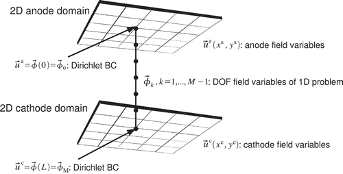
In the framework of our 2+1D approach, the gas channels in the flow-field and bipolar plates of the anode and cathode are discretized in two dimensions (x- and y-directions). The third dimension of the 2D domains is not discretized, but represented by a virtual thickness of the domain in z-direction. The coupling between the anode and cathode side is established by a point-to-point 1D model representing the MEA. Each point of the anode is coupled by the 1D model in z-direction to a mirror point on the cathode side as illustrated in By coupling the anode and cathode in this way, we assume that in-plane transport within the MEA can be neglected. The physical reasoning is that the transport processes in the through-plane direction (z-direction) of the thin MEA layers are dominant in comparison to lateral transport processes within the MEA, and all in-plane transport phenomena are assumed to occur within the 2D anode and cathode domains.
Figure 1. The 2D anodic and cathodic field variables of a PEFC are locally coupled with the 1D MEA model.

This 2+1D model approach is realized by considering the values of the DOF of the 2D model as Dirichlet BCs for the 1D model of the MEA, see The fluxes of the 1D field variables at the 1D boundaries are then converted into volume sources using the virtual thickness of the 2D domains. These volume sources are used as additional source terms in the 2D continuity equations.
Figure 2. With the 2+1D modelling approach all degrees of freedom (DOF) of a 2D anode domain and the opposing 2D cathode domain are coupled with a 1D model. The 2D field values and
are used as Dirichlet BCs
and
to solve a 1D FEM model. The fluxes of the 1D field variables at the 1D boundaries are used as source terms in the 2D continuity equations.
2.1. Mathematical formulation of the 2+1D coupling
The transport problems in the 2D domains of the anode and cathode are solved by the multiphysics finite element tool SESES [Citation36]. For example, governing equations are solved for the electric potential, gas pressure, velocity and concentration of at the anode, and of
at the cathode. These fields can be denoted at the anode as
, and at the cathode as
. Formally, for each such field, we have to solve a 2D governing equation composed of a second-order differential operator
comprising diffusion, convection, inertial terms and a right-hand side
. The right-hand sides of these equations generally do not depend on field derivatives but possibly on all other fields defined within the 2D domains
The exact form of the differential operators ,
and right-hand sides
,
is part of the 2D transport specification. So far, we assume that the two yet uncoupled 2D problems can be solved simultaneously.
To obtain a coupled 2+1D solution, it is assumed that the right-hand side term of the anode model locally depends not only on the anode fields
but also on the cathode fields. Thus, we must consider a dependency of the form
and similarly for the cathode
where each single point on the anode is identified with a point
on the cathode. This is not a too complex amendment to implement in a multiphysics tool but yet requires access to the code. The right-hand side terms EquationEquations (2)
(2) and (3) allow to model the transport through the MEA and thus to couple the anode fields
and the cathode fields
together.
In practice, during the simultaneous solution of the two 2D transport problems, the right-hand sides are evaluated at each integration point of the anode and cathode domains by considering the local field values
. These right-hand side values are used by SESES to build the globally assembled residual equations. One should also correctly specify the derivatives
in order to build a consistent tangent stiffness matrix used in the solution of the residual equations. For other applications than fuel cells, one may think of two simple linear 2D transport problems together with a linear coupling
so that the overall coupled system is linear and can be solved in a single step.
However, a linear coupling of the form cannot be used for a MEA model. The MEA model (see Section 4) is nonlinear and the dependency
is not known in analytical form but must be computed by solving 1D transport equations. The field values on the anode
and cathode
sides are generally paired together and represent the boundary values of some physical fields
within the MEA. If this is not the case, one can always define missing fields as zero-valued fields so that we can assume N = N
a
= N
c
,
and
for a MEA of thickness L. For each field
,
, we have to solve a 1D transport equation in the z-layer and since convection as well as inertial terms can be neglected in the MEA, these transport problems are of the form
with generic diffusion coefficients and right-hand sides
that depend in a coupled way on the fields
. The conditions
and
state that the local anode field values
and the cathode field values
are used as Dirichlet BCs when solving the nonlinear 1D problem of EquationEquation (4)
(4). From a physical point of view, the resulting fluxes of the fields
evaluated at the boundaries of the 1D MEA model yield the right-hand sides and
. Still some unit conversions are needed since the fluxes
are given in per-area units, whereas the right-hand side terms of EquationEquation (1)
(1) have per-volume units. Therefore, we write
where n is the outer normal of the 1D boundaries, and is the virtual thickness of the 2D domains in z-direction according to field variable
. One can think of situations where this virtual thickness is actually different for each field variable, as done in Section 3.
2.2. Numerical details of 2+1D coupling
The numerical solution of the 1D MEA model is achieved by discretizing and solving the transport equations EquationEquation (4)(4) using a Galerkin finite element method. The domain
is partitioned into M elements and at each node
with position
, one defines the Lagrange DOF
with known values
and
. Together with the 1D piecewise linear hat functions
having the property
, one defines the approximations
These approximations are substituted into the transport equations EquationEquation (4)(4). Then, EquationEquation (4)
(4) is multiplied by the 1D hat functions
and a partial integration of the second-order differential term follows. The result is integrated over
to obtain the equations
which need to be solved at the inner nodes . Since the term
is always zero here, we actually have to solve the nonlinear residual equations
for the unknown . This is done with the help of a Newton–Raphson algorithm
where n is the iteration index and some initial solution at
. Due to the local character of the hat functions, each residual
can only depend on the DOF associated with the nodes
and
. The Jacobi matrix
can be also called tangent stiffness matrix
[Citation37], and can be reformulated using EquationEquation (9)
(9):
By interchanging the sequence of partial derivative and integration, the derivation step can be computed analytically using the computer algebra software Mathematica [Citation38]. The analytical expressions of the integrands of the tangent element stiffness matrix, as well as the element residual vector of the 1D MEA model of Section 4 are then exported to C-code, and the integration step is done numerically by an efficient C-code.
When doing these linear algebra computations, the global numbering of the unknown should be chosen so that the Jabobi matrix
is a band matrix of size
. Just few Newton–Raphson iterations are necessary and therefore the solution of EquationEquation (4)
(4) is done in
time.
After a solution has been computed, it is not necessary to explicitly compute the fluxes by EquationEquation (5)(5). By considering the property
and the zero solution property
for
, from EquationEquation (9)
(9) we obtain
By comparing this result with the global conservation law following from EquationEquation (4)
(4) by integration over
, we see that the flux values
and
are nothing than the residuals
and
at the nodes
and
.
To guarantee a good convergence rate of the global 2+1D solution, the derivatives have to be computed. After EquationEquation (6)
(6), and by considering
,
, we need to compute the partial derivatives
The particular case is explained next, whereby the other three cases are handled similarly. The residual
can be considered as a function of the inner DOF
with
and known boundary values of the 1D problem
,
. By considering
and
, we then have
The partial derivatives and
are directly available since they are the same ones used for the Newton–Raphson iteration in EquationEquation (10)
(10) and we are left to compute
. For the inner nodes
, by taking variations of the zero residual relation
with respect to
, we have
where we again used and
. Now EquationEquation (15)
(15) can be solved for
as
The right-hand side vector in EquationEquation (16)(16) is again available from the residual derivatives and has just few non-zero coefficients. The inverse matrix is the Jacobi matrix used in the solution of the Newton–Raphson algorithm EquationEquation (10)
(10) and it is found in LU-factorized form at the end of the solution algorithm. Therefore, the work to compute the partial derivatives of EquationEquation (13)
(13), after having found a solution of EquationEquation (4)
(4), mostly consists in computing
backward–forward substitutions.
3. 2D model of the in-plane processes
Convective and diffusive mass transport is considered in the 2D domains of the flow-field plates. The mass transport is neglected where the plates are in contact with the catalyst layers and therefore the mass transport is just within the gas flow channels. Assuming 2D potential flow conditions in the gas flow channels, the velocity v and pressure distribution P are related by the gradient law
with the viscosity of the gas mixture and
a geometric form factor depending on the third dimension. The value of
was determined by fitting the computed pressure drop between the inlet and outlet to measurements. This approach is similar to the one used for solid oxide fuel cells by [Citation39]. Because this potential flow model is equivalent to a creeping porous flow model,
is named the geometric permeability. The 2D stationary mass balance reads
with the mass density and
the mass production rate. This equation together with EquationEquation (17)
(17) determines the pressure by the solution of a 2D Laplace problem with Dirichlet or Neumann BCs setting the pressure or the total mass flux
at the boundary
where is the gas velocity at the inlet manifold and
is the pressure at the outlet manifold. The gas inlet boundary
is located at the top right of the flow-field, where the gas inlet manifold is positioned (see, e.g. top of (a)). Accordingly, the gas outlet boundary
is located at the top left of the flow-field, where the gas outlet manifold is positioned (see, e.g. top of (b)).
The 2D stationary balance equation for each species is given by
where is the species mass density,
is the species diffusion current and
is the species production rate described by the 1D MEA model. The 1D MEA model also determines the mass production rate
in EquationEquation (18)
(18). The mass density is given by
, and by introducing species mole fractions
, we have
with
the constant species molar masses and
the average molar mass. EquationEquation (21)
(21) can be rewritten by using EquationEquation (18)
(18) in the form
The species diffusion currents are given by , where
are the diffusion coefficients. A first simple approach may use constant values
, but multi-component diffusion according to the Stefan–Maxwell model should be preferred. The solution of EquationEquation (22)
(22) determines the mole fractions
, and the choice of Dirichlet or Neumann BCs set the species mole fraction or some form of the species mass flux at the boundary. The latter depends on the discretization and the associated weak form. Since the condition
must hold, one species balance equation is redundant and can be dropped. However, it is easier to solve for all equations together and to guarantee this consistency numerically. For this fuel cell model, the species to be solved for are
at the anode, and
at the cathode. As an improvement to our creeping flow model, we may abandon the critical relation of EquationEquation (17)
(17) and add the Navier–Stokes equations to compute the velocity as new unknown.
The BCs of EquationEquation (22)(22) are
Here, pure hydrogen and oxygen operation is assumed. Therefore, the species molar fractions are defined by the relative humidity of the reactant gases as listed in .
Table 1. Operation conditions used in simulations
In the 2D domains, the in-plane charge transport in the catalyst layers is accounted for. Charge transport in the in-plane direction is described by a potential equation
and the charge continuity equation
where is the electronic potential in the catalyst layer,
is the electrical conductivity of the catalyst layers in the in-plane direction and
is the contribution of the electrical current in the through-plane direction that is calculated by the 1D MEA model.
The BCs of EquationEquation (25)(25) are
Assuming ideal electrical contact between the flow-field plates and the catalyst layers, the edges of the flow-field ribs define the boundary . Therefore, in-plane charge transport is modelled only between the edges of the flow-field ribs and the active catalyst layer domains.
The operating conditions and BCs used for the 2D calculations are summarized in , and the material properties are given in .
Table 2. Material properties used in 2D and 1D numerical calculations
4. 1D model of the MEA
In the case of the glassy carbon PEFC, the 1D MEA domain consists of three ordered subdomains
, where
represents the anodic catalyst layer,
the membrane domain and
the cathodic catalyst layer. Charge transport in the MEA is described by two potential EquationEquations (41)
(41), one for the electron conducting phase
(EquationEquation (27)
(27)) and one for the proton conducting phase
(EquationEquation (28)
(28)). The continuity equations of both phases (EquationEquations (29)
(29) (30)) are coupled by the charge conservation EquationEquation (32)
(32) [Citation40]. Additionally, both the phases are coupled by the source terms
(EquationEquation (33)
(33)) and
(EquationEquation (34)
(34)). These are the Butler–Volmer equations that describe the electrochemical reactions in the anodic catalyst layer and the cathodic catalyst layer. In the membrane domain, the source terms in EquationEquations (29)
(29) and (30) are zero. The insulating properties of the membrane according to electron transport are incorporated by assuming a negligible electron conductivity,
in
. The current densities are given by
The continuity equations for the electronic charge and the protonic charge are
The BCs of these continuity equations are
The proton conductivity depends on the temperature T and the membrane water content
according to EquationEquation (37)
(37). Charge conservation is accounted for with the following equation:
Using ,
,
and
, the source terms of the continuity equations EquationEquations (29)
(29) and Equation(30)
(30) are
where and
are the exchange current densities on the anode side and the cathode side, respectively.
relates the catalyst layer volume to the active catalyst layer surface,
is the anode hydrogen molar fraction,
is the cathode oxygen molar fraction,
is the symmetry factor, F is the Faraday constant, R is the universal gas constant, T is the temperature,
is the equilibrium potential of the cathode reaction and
is the open-circuit overpotential. The open-circuit overpotential
is used to describe the deviation between the theoretic equilibrium potential of the cathode reaction
and the measurable open-circuit voltage that is mainly caused by species diffusion through the membrane. The reference molar fractions of hydrogen on the anode side
and oxygen on the cathode side
are set to 1.
The right-hand side of the charge continuity equation (EquationEquation (25)
(25)) of the 2D anode domain is represented by the electron flux of the 1D model (EquationEquation (27)
(27)) at the catalyst layer/flow-field plate interface,
. Similarly, the right-hand side
of the charge continuity equation of the 2D cathode domain is calculated as
, where n is the outer normal of the 1D boundaries, and
is the virtual dimension of the catalyst layers in the 2D domains in z-direction.
The molar fractions of hydrogen and oxygen
are assumed to be constant in the catalyst layers. Therefore, the value of
in the continuity equation of the hydrogen species (EquationEquation (22)
(22)) in the 2D anode domain is calculated using Faraday's law by
, where F is the Faraday constant and
is the molar mass of hydrogen.
is the virtual dimension of the gas distribution channels in the 2D domains in z-direction. The value of
in the continuity equation of the oxygen species (EquationEquation (22)
(22)) in the 2D cathode domain is calculated similarly by
, where
is the molar mass of oxygen.
is set to zero in the 2D anode domain, and
is set to zero in the 2D cathode domain.
The model of the MEA accounts for transport of dissolved water in the membrane. The membrane water content is defined as the number of water molecules per sulfonic acid group of the membrane. The total water flux in the membrane
can be described as a combination of electro-osmotic water drag
and diffusive water flux
where is the electro-osmotic drag coefficient,
is the protonic conductivity of the membrane that depends on the temperature T and the membrane water content
,
is the density of the dry membrane,
is the equivalent weight of the membrane and
is the water diffusion coefficient in the membrane.
The protonic conductivity of the membrane is parameterized according to Springer [1]
where is the protonic conductivity at a temperature of 303 K. Constant values for
and
are used as listed in .
The continuity equation for the dissolved water reads
and using EquationEquation (36)(36), this yields
The BCs of this continuity equation are
where a is the water vapour activity in the gas channels.
The source term of dissolved water is given by the rate of water production according to the electrochemical reaction on the cathode side
A parameterization of the ‘sorption isotherm’ of a Nafion membrane measured at is used to calculate the membrane water content as a function of the water activity a in the gas channels [1]
The total water flux is used to determine the source term
of the continuity equation of water vapour (EquationEquation (22)
(22)) in the 2D anode domain. Similarly, the 2D source term on the cathode side
is given by the total flux of dissolved water at the interface between the cathode catalyst layer and the gas distribution channels,
.
The material properties used in the 1D calculations are listed in Table .
5. Neutron imaging of the miniaturized glassy carbon PEFC
A PEFC without GDLs has been developed that delivers up to 700 mW/cm [Citation41]. It includes a catalyst-coated membrane that is surrounded by micro-patterned glassy carbon flow-fields, which ensure a fine gas distribution over the active area. The geometry of the employed flow-fields is a meander that has 11 channels at the gas inlets. Along the flow, the channels are merged to six and finally to three channels, in order to ensure regular water removal [Citation42].
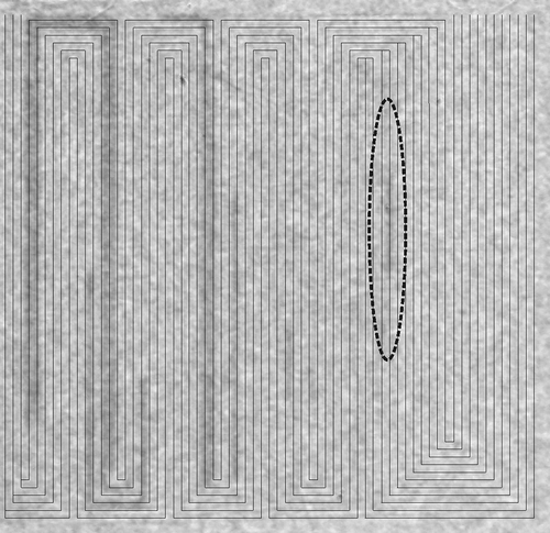
The micro fuel cell was investigated using neutron radiography, which is a powerful method to identify liquid water in operating PEFCs [Citation43,Citation44]. The neutron radiography experiments were performed at the Swiss spallation neutron source SINQ, Paul Scherrer Institute, Villigen, Switzerland [Citation45]. Common fuel cell materials are transparent for neutrons, while liquid water interacts with neutrons. Areas where condensation takes place on the cathode side can be identified in the radiograms. shows a through-plane radiogram that corresponds to an average electric current density of 200 mA/cm. The first location where water condensation takes place is highlighted in the figure. Water condensation is observed already in the first meander, particularly within an area before the merging of two channels. After the junction of the channel with its vicinal channel, the condensed water signal disappears. Liquid water can also be identified in the last four meanders near the outlet of the flow-field.
Figure 3. Through-plane radiogram recorded at operating conditions as listed in Table and at a mean current density of 200 mA/cm (200 mA total cell current). The black lines indicate the centre of the micro-channels and the dark areas represent regions with condensed water. The gas inlets are situated at the top right and the gas outlets at the top left. T = 323 K, relative humidity (RH) = 80%, gas stoichiometries:
,
.
6. Simulation results
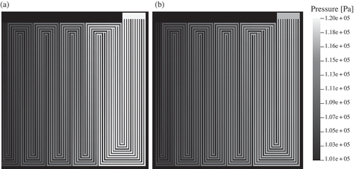
The 2+1D modelling approach was applied to simulate the micro PEFC. The operating conditions are shown in , while the material properties can be found in . shows the resulting absolute value of the gas velocity. The corresponding pressure distribution is shown in
Figure 4. Absolute value of the gas velocity in the flow-field channels ((a) anode, (b) cathode). The gas velocity increases towards the outlet at each channel junction.
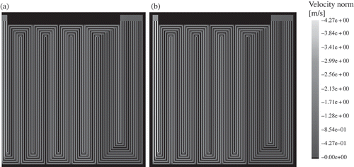
Figure 5. Pressure distribution in the flow-field channels ((a) anode, (b) cathode). At the gas inlets (top right of each domain), the flow rates and the molar fractions of the gas species are specified. At the gas outlets (top left of each domain), the pressure is given. Note that the flow-field includes channels that merge at certain locations that influence the pressure and velocity distribution.
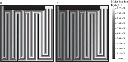
The distribution of the reactant gases is shown in Oxygen and hydrogen are consumed in the electrochemical reactions, and the oxygen molar fraction decreases from 0.91 at the inlet (top right) to 0.69 at the outlet (top left). The hydrogen molar fraction is 0.92 at the inlet; it decreases to 0.78 at the outlet.
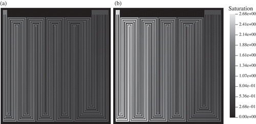
The relative humidity at the gas inlets is set to 80%. Water is accumulated at the cathode side. Therefore, the molar fraction of HO increases towards the cathode outlet. Accordingly, the water vapour saturation increases to 100% already near the inlet as shown in This is due to electrochemical production of water. Water vapour saturation values increase to high values of 2.7 near the outlet on the cathode side. Comparable results could be obtained by neutron radiography on the operating fuel cell (see ). Under these conditions, the model predicts a low-membrane water content of about 8 water molecules per sulfonic group near the gas inlet (). In the cathode domain, this value increases to about 18 near the cell centre and further increases to 20 at the gas outlet. This is due to electrochemical production of water in the cathode catalyst layer and takeup of water by the membrane. The membrane water content at the anode/gas channel interface also increases in the direction of the gas flow. This is because the diffusive water flux through the membrane from the cathode to the anode exceeds the water flux that is due to electro-osmotic drag of water through the membrane from the anode to the cathode (see right part of ).
Figure 8. Membrane water content in number of water molecules per sulfonic acid group ((a) anode, (b) cathode).
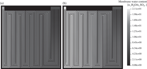
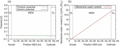
Figure 9. Conditions in the 1D membrane electrode assembly (MEA) model near the outlets of the 2D gas flow channels. (a) Potential distribution of the electronic and the protonic potential. The cathodic Dirichlet BC is set to 0.75 V. This results in a current density of 401.2 mA/cm. The overpotential due to membrane resistance is about 20 mV. (b) Distribution of the membrane water content
. The protonic current density in the anode catalyst layer (CL) increases towards the membrane (MEM). The increasing electro-osmotic drag of water in the anode CL towards the membrane leads to the curvature of
in the anode CL. In the cathode CL, the decreasing protonic current density and the electrochemically produced water are leading to a negative curvature of
.
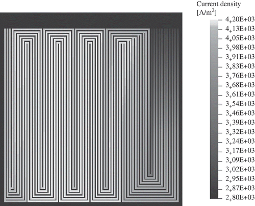
The electrical current density of the cathode domain in the through-plane direction is shown in This current density is predicted by the 1D model, that is, in the direction perpendicular to the cell area. The current density is zero where the flow-field plates are in contact with the catalyst layers, because of the assumption of no mass transport in the catalyst layers under the flow-field plates. Positive charge is transferred from the anode to the cathode. The current density is lowest near the gas inlet (top right); it increases to a maximum value in the cell centre and decreases towards the gas outlet (top left). The minimum value of the current density near the gas inlet is due to a low value of the membrane humidification, that is the protonic conductivity in this region is lowest here. An increase of the membrane water content is found in the cell centre.
Figure 10. Electric current density (cathode) in the through-plane direction as calculated by the 1D model, that is in the direction perpendicular to the cell area.
The distribution of the electronic and protonic potential in the 1D MEA model near the outlet of the gas flow channels is shown in (a). The distribution of the membrane water content in the 1D MEA model at the same position within the 2D domains is shown in (b).
Although the model does not account for two-phase flow in the channels, the areas can be identified where condensation takes place due to over-saturation of the gas flows with water. As explained above, the water flux is caused by the electrochemical reaction, electro-osmotic drag of water and water diffusion. displays the calculated flux of water, , that is transferred between the 1D MEA model and the 2D model. On the anode side,
can be interpreted as net membrane water flux, whereas on the cathode side,
is the net membrane water flux plus the flux that results from the electrochemically produced water in the cathode catalyst layer. On the anode side, the following features can be identified: the sign of the net membrane water flux changes over the fuel cell area, that is the direction of the water transport changes with respect to the through-plane coordinate. The electro-osmotic water drag is dominant close to the gas inlet. The inlet region is followed by a region where water back diffusion is dominant on the first straight part of the flow-field channels. Electro-osmotic drag and water back diffusion are balanced at the second long straight part of the flow-field channels. Back diffusion of water from the cathode to the anode is dominant in the remaining part of the flow-field.
Figure 11. Calculated water flux that is transferred between the 1D MEA model and the 2D domains ((a) anode, (b) cathode). The maximum water flux from the MEA to the cathode corresponds to the liquid water signal at the end of the first meander in the neutron radiography (see ).
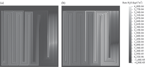
The cathode shows the following features. at the cathode is positive over almost the whole cell area. There, the water flux that originates from the electrochemical production of water exceeds the flux that is due to water back-diffusion to the anode. Only at a minimum of
that is found on the first straight part of the flow-field,
is slightly negative. A maximum of
is predicted in the flow-field region that is situated in front of the first merging of the flow-channels, and not where the maximum current density is found (see ). This region, where the calculated maximum of the water flux to the cathode is situated, corresponds to the cell region containing the first meander. This simulation result is validated experimentally: in this region, liquid water is visible in the neutron radiogram (see ). After the merging of the micro-channels, the predicted water flux to the cathode side is reduced in comparison to the area before the junction, and the liquid water signal in the neutron radiogram disappears. Back diffusion of water through the membrane is identified as the reason. Liquid water can be also identified in the neutron radiogram in regions where the meanders consist of six parallel channels. There, the model predicts a water vapour saturation of at least 1.7 or higher (see ). After the merging of the micro-channels from six to three, the liquid water signal in neutron radiogram disappears. This correlates with the increased gas velocity in the last straight channels of the flow-field (see ).
7. Conclusions
A computationally efficient model of a PEFC is presented. It is based on a 2+1D approach, where the gas flow-fields on the anode side and on the cathode side are discretized in two dimensions. The MEA is modelled in one dimension.
The 2+1D model is applied to simulate a micro PEFC with glassy carbon structures. The cell contains a serpentine-shaped flow-field. An inhomogeneous distribution of the electrical current density with a maximum value at the mid-length of the flow-channels is found. The membrane humidification is found to be higher on the cathode side in comparison to the humidification value on the anode side, whereby the membrane humidification is more pronounced towards the cell outlet. The membrane water transport is highly inhomogeneous over the cell area. There are cell regions where electro-osmotic drag dominates, and others where back diffusion of water from the cathode side to the anode side is dominant. Moreover, areas are identified where both water transport processes compensate each other.
The calculated flux of water that is transferred between the MEA and the cathode is compared to the neutron radiography data of the micro PEFC under operation. Similar features of the water distribution are found. The 2+1D model is successfully used to explain in which cell region the water condensation occurs due to a maximum water flux to the cathode.
It is concluded that the 2+1D approach is suitable to take the high aspect ratio between the in-plane and the through-plane dimensions of a PEFC into account. This is essential to describe large-area fuel cells. By using the 2+1D approach, the DOFs of the model are significantly reduced in comparison to a full 3D discretization of the model domain.
The purpose of this work has been to demonstrate the ability of the 2+1D model approach to simulate spatially distributed effects in PEFCs and to capture the complex interactions between the transport and reaction processes in fuel cells with complex flow-field shape. There are several extensions to the model that we are currently pursuing. Diffusion of the reactant gases in the porous electrodes must be included. In addition, the inclusion of energy transport will provide the temperature distribution within the fuel cell.
Acknowledgements
The authors acknowledge the support during the neutron radiography measurements by Pierre Boillat and Gabriel Frei. Thanks are also due to Adrian Gentsch for help during preparation of the manuscript. Financial support by the GEBERT RÜF FOUNDATION in Switzerland is also gratefully acknowledged.
References
- Springer , T.E. , Zawodzinski , T.A. and Gottesfeld , S. 1991 . Polymer electrolyte fuel cell model . J. Electrochem. Soc. , 138 : 2334 – 2342 .
- Bernardi , D.M. and Verbrugge , M.W. 1992 . A mathematical model of the solid-polymer-electrolyte fuel cell . J. Electrochem. Soc. , 139 : 2477 – 2491 .
- Baschuk , J.J. and Li , X. 2000 . Modelling of polymer electrolyte membrane fuel cells with variable degrees of water flooding . J. Power Sources , 86 : 181 – 196 .
- Djilali , N. and Lu , D. 2002 . Influence of heat transfer on gas and water transport in fuel cells . Int. J. Thermal Sci. , 41 : 29 – 40 .
- Weber , A. and Newman , J. 2006 . Coupled thermal and water management in polymer electrolyte fuel cells . J. Electrochem. Soc. , 153 : A2205 – A2214 .
- Fuller , T.F. and Newman , J. 1993 . Water and thermal management in solid-polymer-electrolyte fuel cells . J. Electrochem. Soc. , 140 : 1218 – 1225 .
- Nguyen , T.V. and White , R.E. 1993 . A water and heat management model for proton-exchange-membrane fuel cells . J. Electrochem. Soc. , 140 : 2178 – 2186 . E,F.
- Yi , J.S. and Nguyen , T.V. 1998 . An along-the-channel model for proton exchange membrane fuel cells . J. Electrochem. Soc. , 145 : 1149 – 1159 .
- Dannenberg , K. , Ekdunge , P. and Lindbergh , G. 2000 . Mathematical model of the PEMFC . J. Appl. Electrochem. , 30 : 1377 – 1387 .
- Siegel , N. , Ellis , M. , Nelson , D. and Spakovskyvon , M. 2004 . A two-dimensional computational model of a PEMFC with liquid water transport . J. Power Sources , 128 : 173 – 184 .
- Natarajan , D. and Nguyen , T.V. 2001 . A two-dimensional, two-phase, multicomponent, transient model for the cathode of a proton exchange membrane fuel cell using conventional gas distributors . J. Electrochem. Soc. , 148 : A1324 – A1335 .
- Berning , T. , Lu , D. and Djilali , N. 2002 . Three-dimensional computational analysis of transport phenomena in a PEM fuel cell . J. Power Sources , 106 : 284 – 294 . C.
- Mazumder , S. and Cole , J. 2003 . Rigorous 3D mathematical modeling of PEM fuel cells II. Predictions with liquid water transport . J. Electrochem. Soc. , 150 : A1510 – A1517 .
- Um , S. and Wang , C.Y. 2004 . Three dimensional analysis of transport and electrochemical reactions in polymer electrolyte fuel cells . J. Power Sources , 125 : 40 – 51 .
- Nguyen , P.T. , Berning , T. and Djilali , N. 2004 . Computational model of a pem fuel cell with serpentine gas flow channels . J. Power Sources , 130 : 149 – 157 .
- Senn , S. and Poulikakos , D. 2004 . Polymer electrolyte fuel cell with porous materials as fluid distributors and comparisons with traditional channeled systems . J. Heat Transfer , 126 : 410 – 418 .
- Hu , G. , Fan , J. , Chen , S. , Liu , Y. and Cen , K. 2004 . Three-dimensional numerical analysis of proton exchange membrane fuel cells (PEMFCs) with conventional and interdigitated flow fields . J. Power Sources , 136 : 1 – 9 .
- Ju , H. , Meng , H. and Wang , C. 2005 . A single-phase, non-isothermal model for PEM fuel cells . International J. Heat Mass Transfer , 48 : 1303 – 1315 .
- Wang , C.Y. and Cheng , P. 1996 . A multiphase mixture model for multiphase multicomponent transport in capillary porous media - I. Model development . Int. J. Heat Mass Transfer , 39 : 3607 – 3618 .
- Berning , T. and Djilali , N. 2003 . A 3D, multiphase, multicomponent model of the cathode and anode of a PEM fuel cell . J. Electrochem. Soc. , 150 : A1589 – A1598 .
- Pasaogullari , U. and Wang , C.Y. 2005 . Two-phase modeling and flooding prediction of polymer electrolyte fuel cells . J. Electrochem. Soc. , 152 : A380 – A390 .
- Ziegler , C. , Yu , H.M. and Schumacher , J.O. 2005 . Two phase dynamic modeling of the PEMFC and simulation of cyclovoltammograms . J. Electrochem. Soc. , 152 : A1555 – A1567 .
- Jiao , K. , Zhou , B. and Quan , P. 2006 . Liquid water transport in straight micro-parallel-channels with manifolds for PEM fuel cell cathode . J. Power Sources , 157 : 226 – 243 .
- Ye , Q. and Nguyen , T.V. 2007 . Three-dimensional simulation of liquid water distribution in a PEMFC with experimentally measured capillary functions . J. Electrochem. Soc. , 154 : B1242 – B1251 .
- Steinkamp , K. , Schumacher , J.O. , Goldsmith , F. , Ohlberger , M. and Ziegler , C. 2008 . A non-isothermal PEM fuel cell model including two water transport mechanisms in the membrane . J. Fuel Cell Sci. Technol. , 5 : 011007 – 011022 .
- Wua , H. , Li , X. and Berg , P. 2009 . On the modeling of water transport in polymer electrolyte membrane fuel cells . Electrochim. Acta , 54 : 6913 – 6927 .
- Bautista , M. , Bultel , Y. and Ozil , P. 2004 . Polymer electrolyte membrane fuel cell modelling - d.c. and a.c. solutions . Chemi. Eng. Res. Des. , 82 : 907 – 917 .
- Berg , P. , Promislow , K. , St. Pierre , J. , Stumper , J. and Wetton , B. 2004 . Water management in PEM fuel cells . J. Electrochem. Soc. , 151 : A341 – A353 .
- Kulikovsky , A.A. 2004 . Semi analytical 1D + 1D model of a polymer electrolyte fuel cell . Electrochemi. Commun. , 6 : 969 – 977 .
- Freunberger , S. , Santis , M. , Schneider , I. , Wokaun , A. and üchi , F.N. B . 2006 . In-plane effects in large-scale PEMFC's - Model formulation and validation . J. Electrochem. Soc. , 153 : A396 – A405 .
- Lottin , O. , Antoine , B. , Colinart , T. , Didierjean , S. , Maranzana , G. , Moyne , C. and Ramousse , J. 2009 . Modelling of the operation of polymer exchange membrane fuel cells in the presence of electrode flooding . Int. J. Thermal Sci , 48 : 133 – 145 .
- Kulikovsky , A.A. 2001 . Quasi three-dimensional modelling of the PEM fuel cell: comparison of the catalyst layers performance . Fuel Cells , 1 : 162 – 169 .
- Kulikovsky , A.A. 2003 . Quasi-3D modeling of water transport in polymer electrolyte fuel cells . J. Electrochem. Soc. , 150 : A1432 – A1439 .
- Mueller , F. , Brouwer , J. , Kang , S. , Kim , H.S. and Min , K. 2007 . Quasi three dimensional dynamic model of a proton exchange membrane fuel cell for system and controls development . J. Power Sources , 163 : 814 – 829 .
- Siegel , C. 2008 . Review of computational heat and mass transfer modeling in polymer-electrolyte-membrane (PEM) fuel cells . Energy , 33 : 1331 – 1352 .
- G. Sartoris, NM-SESES: finite element software for computer aided engineering (2011). http://www.icp.zhaw.ch (http://www.icp.zhaw.ch)
- Reddy , J.N. 2004 . An introduction to nonlinear finite element analysis , Oxford : Oxford University Press .
- S. Wolfram, Mathematica 7, (2010). www.wri.com (http://www.wri.com)
- Roos , M. , Batawi , E. , Harnisch , U. and Hocker , T. 2003 . Efficient simulation of fuel cell stacks with the volume averaging method . J. Power Sources , 118 : 86 – 95 .
- Newman , J. and Tiedemann , W. 1975 . Porous-electrode theory with battery applications . AIChE , 21 : 25
- Seyfang , B.C. 2009 . Simplification and miniaturization of poymer electrolyte fuel cells using micro-patterned glassy carbon flow fields dissertation No 18508, ETH Zürich
- Seyfang , B.C. , Boillat , P. , Simmen , F. , Hartmann , S. , Frei , G. , Lippert , T. , Scherer , G.G. and Wokaun , A. 2010 . Identification of liquid water constraints in micro polymer electrolyte fuel cells without gas diffusion layers . Electrochim. Acta , 55 : 2932 – 2938 .
- Kramer , D. , Zhang , J. , Shimoi , R. , Lehmann , E. , Wokaun , A. , Shinohara , K. and Scherer , G.G. 2005 . In situ diagnostic of two-phase flow phenomena in polymer electrolyte fuel cells by neutron imaging: Part A. Experimental, data treatment, and quantification . Electrochim. Acta , 50 : 2603 – 2614 .
- Boillat , P. , Kramer , D. , Seyfang , B.C. , Frei , B. , Lehmann , E. , Scherer , G.G. , Wokaun , A. , Ichikawa , Y. , Tasaki , Y. and Shinohara , K. 2008 . In situ observation of the water distribution across a PEFC using high resolution neutron radiography . Electrochem. Commun. , 10 : 546 – 550 .
- Fischer , W. 1997 . SINQ- The spallation neutron source, a new research facility at PSI . Physica B , 234–236 : 1202 – 1208 .
