Abstract
A systematic approach for the dynamical modelling of the unsteady flow over a flapping wing is developed, which is based on instantaneous velocity field data of the flow collected using particle image velocimetry (PIV) and computational fluid dynamics (CFD) simulations. The location and orientation of the airfoil is obtained by image processing and the airfoil is filled with proper velocity data. Proper orthogonal decomposition (POD) is applied to these post-processed images to compute POD modes and time coefficients, and a discrete-time state-space dynamical model is fit to the trajectories of the time coefficients using subspace system identification (N4SID). The procedure is verified using PIV and CFD data obtained from a pitching NACA0012 airfoil. The simulation results confirm that the dynamical model obtained from the method proposed can represent the flow dynamics with acceptable accuracy.
1. Introduction
Using flapping wings to achieve flight is a topic of active research that has recently received significant attention in the literature, especially in the area of micro air vehicles (MAVs). MAVs using flapping wings have important advantages over conventional rotary-driven aircraft such as higher manoeuvrability, increased efficiency, more lift and reduced noise [Citation1–3]. Flapping wing air vehicles are currently used in military applications such as aerial reconnaissance without alerting enemies, in wildlife applications for studying endangered species, for scaring away birds in airports that cause damage to aircraft engines and for entertainment purposes by hobbyists and toy manufacturers [Citation4]. Understanding and modelling the aerodynamics of the flow of air over flapping wings is important because it can help improve the advantages. However, the aerodynamics of flapping motion is a complex non-linear system because of the unsteady interaction between the vortex topologies, and it is therefore difficult to model accurately [Citation5]. Efforts in this direction by our group include the work of Kurtulus [Citation6], in which artificial neural networks are used to model the input–output responses to capture the most significant features of unsteady flapping motion, and of Kurtulus et al. [Citation7], in which numerical and experimental models are constructed using direct numerical simulations, laser sheet visualizations and particle image velocimetry (PIV) measurements to understand the aerodynamics and vortex formation mechanism during the different phases of unsteady flapping motion. Other works on this topic include the work of Deng et al. [Citation8], who developed a model that captures the main dynamical features of a micromechanical flying insect capable of sustaining self-governing flight through the use of linear estimation methods, and of Zbikowski [Citation9], who introduced a conceptual structure for the aerodynamic modelling of an insect-like flapping wing in hover for MAVs and proposed two analytic approaches.
As it is the case for any flow process, physical meaning of the flow over flapping wings can be understood and analysed mathematically by describing the flow in terms of velocity vectors and representing it with dynamical models. The governing equations for fluid flows are the Navier–Stokes (NS) partial differential equations (PDEs), which are capable of representing these flows very accurately; however, due to their complexity, they are very difficult to analyse and most of the time obtaining an analytical solution is not possible [Citation10]. For this reason, techniques such as proper orthogonal decomposition (POD) are used to obtain a simpler representation of the velocity field and provide a convenient means to analyse the flow behaviour. POD is a technique to decompose a flow velocity field into spatial modes (POD modes) and time-dependent amplitudes (time coefficients). The POD method extracts deterministic functions associated with large-scale energetic structures in a flow. One can find many studies regarding fluid flows using POD methods including the work by Noack et al. [Citation11], who studied low-dimensional models for the transient and post-transient cylinder wake and obtained reduced-flow methods by Galerkin projection (GP), and the works by our group including Erbil and Kasnakoglu [Citation12], where wavelet-based functions are used for the decomposition to achieve a spatially local model. Additional examples include the model reduction for compressible isentropic flows using POD and GP by Rowley et al. [Citation10] and balanced model reduction using POD by Wilcox and Peraire [Citation13]. Also, Tran and Ly [Citation14] applied POD to the modelling and control of a complex flow process, namely the Rayleigh–Bénard convection phenomena. By using POD, reduced-order modelling for unsteady transonic flows around an airfoil is completed by Bourguet et al. [Citation15], where POD analysis was used to identify buffeting and von Karman instability which are two main unsteady phenomena induced by compressibility effects that describe the physics of flow. An excellent reference on reduced-order modelling for flow control, including techniques mentioned above, is the book by Noack et al. [Citation16].
Because the POD technique requires instantaneous velocity information (i.e. snapshots) to decompose the flow, the PIV measurement technique can be used to obtain experimental data for the unsteady velocity field. Details of the PIV technique such as PIV algorithms, optical considerations, tracer particles, illuminating lasers, recording hardware, errors in PIV measurements and PIV vector processing can be found in the works of Prasad et al. [Citation17] and Raffel et al. [Citation18]. Studies on PIV include the work of Scarano and Riethmuller [Citation19], who proposed an improved algorithm based on cross-correlation for the interrogation of PIV images in flow problems by predicting the displacement of interrogation areas by means of an iterative procedure. Daichin et al. [Citation20] investigated the influence of a water surface on the structure of the trailing wake of an NACA0012 airfoil using PIV measurements of the flow at different ride heights between the airfoil and the surface. Works that are most significant and related to this article are probably on the use of PIV measurements as the set of snapshots required to obtain the POD modes. These include the works of Druault et al. [Citation21], who reconstructed the 3D in-cylinder mean flow field from PIV data by using POD, and of Druault et al. [Citation22], who used POD for time interpolation from PIV data found in in-cylinder engine flow.
Although PIV measurements provide an experimental means to obtaining the instantaneous flow velocity profile, one may not have enough resources or time to physically build the experimental set-up necessarily needed to test a particular flow case. In these cases, it is reasonable to resort to computational fluid dynamics (CFD) simulations, which have been proven to provide very accurate representations of the actual flow processes [Citation23,Citation24]. The CFD simulation results can be used to construct the instantaneous images required for the POD process, the examples of which include the works of Ravindran [Citation25] who has built adaptive controllers for fluid flow, Bleris and Kothare [Citation26] who have studied reduced-order distributed boundary control of thermal transients in microsystems and Kowalski and Jin [Citation27] who have constructed reduced-order models of non-linear models of electromagnetic phased-array hyperthermia.
In the existing literature, the usual procedure for the reduced-order modelling of fluid flows is to apply GP following POD. This procedure involves substituting the POD expansion into the governing equations (mostly the NS PDEs) and isolating the dynamics of the time coefficients, with certain approximations and truncations necessary. For instance, Rowley et al. [Citation10] obtained models for compressible isentropic flows by using GP, and Gerhard et al. [Citation28] obtained low-dimensional Galerkin models to control vortex shedding. Although widely employed, GP is relatively complicated in terms of mathematical manipulations and it is prone to numerical errors as it involves computations on the NS equations and requires that certain terms be ignored in the approximation. Certain improvements and modifications have been proposed to the POD/GP approach including determination of free parameters in the POD/GP system from flow simulations via a minimization problem [Citation29] and using interspersed intervals whose lengths are chosen according to several ideas that include an a priori estimate of the error of the Galerkin approximation [Citation30]. Even though these approaches are major improvements over the traditional approaches, GP is still part of the picture.
In this article, we propose identifying the model directly from the POD time coefficients, hence skipping GP and replacing it with system identification (SI). SI techniques are well established and reliable numerical software is widely available. In addition, SI procedures perform tuning by directly operating on the data without going through any mathematical manipulations on the NS equations, eliminating another source of potential error. In particular, we outline a systematic application of PIV, CFD, POD and SI to the problem of obtaining dynamical models to represent the flow over a flapping wing. The proposed approach is based on experimentally obtaining PIV or CFD snapshots of the flow, and then numerically processing these snapshots to construct the spatial POD modes and the temporal time coefficients. SI techniques are then used to fit a dynamical model to the time coefficients. The flow is reconstructed using these dynamical models, and it is observed that the results are sufficiently close to the reconstructions obtained from POD coefficients as well as the original snapshots obtained from PIV or CFD.
At this point, it is worth mentioning that the main goal of flapping wings is to generate thrust for the air vehicle, and one can find many studies in the literature regarding this topic. However, in this article we do not concentrate on the trust generation process through wing flapping but instead we investigate the flow structures formed as a result of wing flapping. The experiments were also set up with this goal in mind: the experimental set-up locks the wing in place so that no translational motion takes place and the only motion is the rotation of the wing at the quarter-chord length from the leading edge. Together with the fluid at rest, this represents a hovering-type scenario, for example, when the air vehicle is flapping wings at a constant altitude without moving horizontally. The goal is to study the shape and intensity of the flow structures resulting from flapping wings while hovering and build mathematical models to capture their dynamics. These structures are important as the vortices formed can be quite intense and could cause problems such as airframe fatigue as well as noise and vibration on the vehicle, affecting flight safety and performance. Hence, having mathematical models to represent these effects gives us the potential to analyse and perhaps later reduce (via control design) these unwanted characteristics.
The rest of the article is organized as follows: Section 2 presents the methodology for the dynamical modelling procedure. Section 3 illustrates results of applying the proposed methods to two example scenarios regarding flapping wings. Section 4 presents an overall quantitative comparison of the results. Section 5 concludes the article with some discussions and future research directions.
2. Methodology
The method proposed in this article consists of three main parts. The first task is to obtain the instantaneous velocity vectors of the flow using PIV and CFD techniques. These measurements are then input to the POD procedure so as to decompose the flow into its spatial components, that is, the POD modes, and its temporal components, that is, the time coefficients. The final step is to fit a dynamical state-space model using SI techniques to the trajectories of the time coefficients.
2.1. Instantaneous flow field measurements using PIV technique to obtain data for the autonomous and slow pitching case
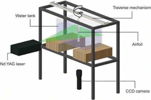
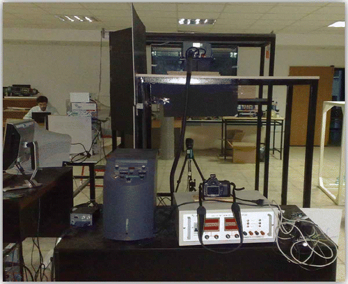
PIV is a non-intrusive measurement technique that allows observing the instantaneous flow field [Citation18]. A schematic illustration of the PIV set-up used in our experiments is shown in , and a photograph of the set-up is shown in Flow properties and PIV parameters are tabulated in . The set-up consists of an Nd:YAG laser, a charge-coupled device (CCD) camera and a lens system. In the PIV system, different particle seeds in the flow field are used to reflect the beam of Nd:YAG laser, which flashes in discrete time with a definite frequency to the CCD camera. In our case, silver-coated hollow sphere particles with 10 μm average diameter are used for the visualization of the vector field. The concentration of the seeding inside the water tank is 4.75 × 10⁻⁵ g/cm3. The experimental set-up includes a plexiglass water tank of 40 cm × 40 cm × 80 cm length. Inside the tank, the pitching motion of a wing takes place, which is performed by a traverse system placed on top of the water tank. A FlowSense 2M CCD camera is placed under the water tank to obtain instantaneous velocity field around the airfoil at a section. The focal length of the CCD camera is 60 mm and the frame rate is 5 Hz. Therefore, the system can take 50 double images in a period of motion (T = 10 s). The resolution of the snapshots is 1600 × 1200 pixels. In order to collect velocity data, it is necessary to calibrate the system before the experiment to convert pixel to metres. The power of the Nd:YAG laser is 120 mJ/pulse. The time separation is 10,000 μs, which allows a displacement of about 8 pixels. Adaptive correlation is applied. In the experiments, an NACA0012 wing is used. The chord length of the wing is 6 cm and the span is 30 cm. The centre of rotation is located at the quarter chord of the airfoil from the leading edge. The traverse system comprises two step motors. The first motor allows the translational motion and the second motor is associated with the rotation of the wing. The useful rotational motion is of 360°. The motor is connected to the quarter chord of the airfoil; therefore, angular displacement of quarter chord is zero. As this study deals with flapping motion in hover mode, the pitching motion is carried out in zero free-stream velocity. The pitching motion of the airfoil is provided by a motor, which is mounted on the traverse system. The period of the pitching motion is 10 s and maximum angular velocity is 0.329 rad/s. This generates a flow of Reynolds number 188, computed from the mean flow velocity over the wing, the density of the fluid (water) and the chord length. The signals that provide the movement of the motors are generated by a MATLAB/Simulink program. The camera and Nd:YAG laser operate in synchronized fashion to capture the reflection from the particles. The captured double images are processed by Dantec Studio program employing the adaptive cross-correlation method [Citation31]. This is used to construct the velocity vectors by finding differences between sequential snapshots [Citation32]. In order to extract the velocity information from the PIV images of the particles, interrogation analysis is needed. PIV images are analysed by dividing the images into small interrogation regions [Citation33]. Smaller interrogation window size is preferable because it can give better spatial resolution of the PIV measurements. However, if the window size is too small, it can cause inaccurate velocity vectors. Interrogation is done by adaptive cross-correlation method [Citation34,Citation35]. The resolution of interrogation area is 32 × 32 pixels. The output of the process is the velocity vector fields, that is, the x and y velocities of the snapshots, which are then imported into MATLAB.
Table 1. Flow properties and PIV parameters
To use the PIV data for POD and SI, a preprocessing of the snapshots is needed to determine the geometry of the airfoil; this must be done at each time instant since the airfoil is in motion. For this purpose, an image processing algorithm in MATLAB was developed for masking the airfoil. By using MATLAB Image Processing Toolbox, techniques such as image enhancement, noise elimination, morphological operations and edge detection were applied in proper sequence to each PIV snapshot to determine the geometric properties of the airfoil such as the leading edge, trailing edge, quarter-chord location, coordinates of its surface and pitch angle. Once the geometry of the airfoil is obtained by the image processing algorithm, velocity information is added inside the airfoil and on its surface. This is because in the flow field the streamlines cannot penetrate the airfoil as it is a solid body. In addition, it is simpler to apply the POD method if the velocity information is available for all points within the snapshots. The airfoil performs a sinusoidal pitching motion, where the instantaneous pitch angle in radians is given by
where ,
is the frequency of the motion and t is the time variable. The angular velocity
in rad/s with respect to the quarter chord of the airfoil is given by the expression
As the x–y coordinates of the airfoil's surface and the angular velocity are known for each snapshot, the velocity vectors
inside the moving airfoil and on its surface can be calculated by
where r is the position vector relative to the quarter chord and k is the unit vector in the z-direction.
2.2. Recording flow field snapshots using CFD simulations to obtain data for the actuated and fast pitching case
To obtain a model with actuation and fast pitching, we use CFD simulations of a NACA0012 airfoil, which are pitching while simultaneously injecting fluid normal to the surface out of a slit located on the surface. For the sake of example, we place the slit on the upper camber towards the leading edge; this selection does not cause any loss of generality in the modelling procedure and it could be relocated as needed for a different problem. The CFD simulations are carried out using FLUENT 6.3. The portion of the grid around the airfoil is shown in The whole CFD domain is a circle of radius 1.5 m with the wing of chord length 0.06 m at its centre. The large domain size is necessary for the accuracy of the CFD simulations involving shedding of vortices. For the modelling studies, the data obtained from CFD are later clipped to a smaller square domain . The entire grid contains 25,631 nodes and is more concentrated around the airfoil and its trailing region, because these are the areas where most of the activities take place. The location for the actuation on the airfoil is shown by red circle in the figure. The diameter of the slit is about 8 mm. The simulations are carried out in 2D with double precision using the pressure-based NS solver of FLUENT. Wall boundary conditions are used on the wing except for the slit, which is a velocity inlet normal to the boundary. The flow velocity at the inlet is specified by a user-defined function (UDF). The circle encapsulating the whole domain is specified as an outflow boundary. The mesh is rotated dynamically by the use of a UDF to achieve the pitching motion described in EquationEquation (2)
(2), but instead of 0.1 Hz we select the pitching frequency to be f = 10 Hz to achieve the fast pitching motion.Footnote
1
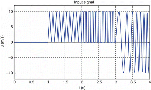
The solver is configured to obtain unsteady solutions and record time data at a time step of 0.01 s for 400 time steps, for a total of 4 s. The actuation is achieved by means of a UDF, and the system is actuated through the location shown in the figure. The input applied to the system by the actuator (see ) is a combination of four different signals: zero input, triangle wave, square wave and a chirp signal. These signals reveal, respectively, the system's dynamical response under no excitation (only pitching), time-varying actuation, constant excitation with sudden jumps and sinusoidal actuation at a range of frequencies. The chirp signal is especially important and has been successfully used in previous works on flow modelling, for example, the work of Bergmann et al. [Citation36]. This signal also includes a negative component so as to model the effect of sucking in fluid from the actuator location. These composite input signals excite a wide range of dynamical modes of the flow process that can be exploited by model identification techniques in the succeeding sections. The pitching motion, together with the injection, generates a flow of Reynolds number 4768, computed from the mean flow velocity over the wing, the density of the fluid (water) and the chord length.
Figure 3. The location for actuation (red) on the airfoil shown within the grid used for CFD (green).

Remark:
At this point, it is worth making the clarification that the pitching motion of the wing is prescribed, that is, it is not caused and is not affected by the injection through the slit. The injection through the slit is meant to demonstrate the proposed method's capability of handling actuated flow.
2.3. Applying POD to the snapshots to obtain the POD modes and time coefficients
POD is an effective method of data analysis using which high-dimensional processes can be described by low-dimensional approximations. A flow velocity field can be decomposed into spatial modes and time-dependent amplitudes by using POD; this method is also known as the Karhunen–Loève decomposition [Citation14]. In this article, we use the method of snapshots approach for POD, for which first some snapshots of the flow are collected from an experimental (e.g. PIV) or a numerical system (e.g. CFD). After collecting the data, POD technique produces a set of basis functions that optimally represent the spatial distribution of the snapshots collected. Each POD basis function captures a certain percentage of the energy of the flow field [Citation32,Citation35]. One can choose a certain number (N) of POD modes to capture a sufficient amount of the flow energy and then represent the flow field as a finite-dimensional approximation as
where are time coefficients,
are the POD modes of the ensemble and
is the average flow velocity. To obtain the POD modes
of the flow field, one first obtains a set of instantaneous velocities (snapshots)
, where
and
is the ith time instant where measurements are taken. The average of the ensemble of snapshots can then be computed as
where is the number of snapshots. Then a new set of snapshots (
) are obtained by subtracting this mean value from each velocity measurement
Next, the spatial correlation matrix C of the ensemble is constructed as follows:
where denotes the inner product over the flow domain
that can be approximated over the set of grid points
using a suitable quadrature rule. The eigenvalue equation
is solved to obtain the time coefficients at time instants , that is,
. The coefficients are scaled such that
The POD modes are then computed as
It can be shown that the POD modes obtained using this procedure are orthonormal, that is, they satisfy
The eigenvalue represents the amount of energy of the flow field captured by the ith POD mode
. Based on this energy information, one can decide on the number of POD modes (N) to include in the approximation (4). By including N modes, the approximation captures
of the total flow energy. The procedure described for obtaining the POD approximation of the flow is termed the method of snapshots, the details of which can be found in Holmes et al. [Citation37] and Sirovich [Citation38]. In this study, this is the procedure applied to the post-processed PIV or CFD snapshots of the pitching airfoil in order to obtain an expansion of the form given in EquationEquation (4)(4).
2.4. System identification
Once the POD modes are obtained and the flow is expanded as in EquationEquation (4)(4), it can be observed that the time variation is dictated only by the coefficients
because the modes
depend only on the spatial variables
and not on the time variable
. Hence, to model the flow dynamics, it is sufficient to fit a suitable dynamical model to the trajectories of the time coefficients
. For this purpose, we derive a state-space model of the following form:
where is the state vector,
is the degree of the system,
is control input and
is the output signal. As the flow snapshots are obtained at discrete time intervals separated by a sampling period of
seconds, the above model is a discrete-time state-space model. The matrices A, B, C and D determine the dynamical system and are obtained by constructing a model from EquationEquations (13)
(13) and (14) using SI techniques. For this purpose, the input–output data must be collected for the system, which is usually done by applying various input signals (e.g. sine waves, ramp functions and chirp signals) and recording the resulting outputs, which are the time coefficients of the expansion, that is,
where N is the number of POD modes used in the expansion. From the input–output data, subspace SI method (N4SID) is used for obtaining the A, B, C and D matrices in EquationEquations (13)(13) and (14). The main idea behind the subspace method is to first estimate the extended observability matrix
for the system from input–output data by direct least-squares like projection steps. In particular, it is possible to show that an expression of the form
can be obtained from EquationEquations (13)(13) and (14), where
and is the contribution because of output noise. The extended observability matrix
can then be estimated from EquationEquation (17)
(17) by correlating both sides of the equality with quantities that eliminate the term
and make the noise influence from
disappear asymptotically. Once
is known, it is possible to determine C and A by using the first block row of
and the shift property, respectively. Once A and C are at hand, B and D are estimated using linear least squares on the following expression:
where EquationEquation (21)(21) is a representation of the system described by EquationEquations (13)
(13) and (14) in terms of the time-shift operator z. This last step may be skipped in case of an autonomous model (as B and D will be absent). Details of the subspace method for estimating state-space models can be found in Ljung [Citation39], Van Overschee and De Moor [Citation40] and Larimore [Citation41].
3. Results
3.1. Example 1: autonomous model of a slow-pitching NACA0012 airfoil using PIV measurements
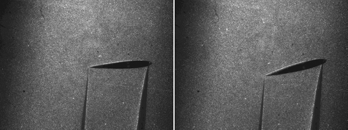
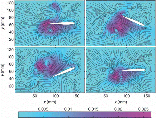
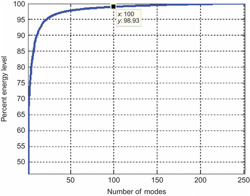
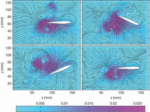
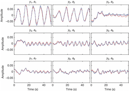
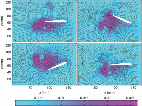
In this section, the results of applying the methodology described in the previous sections to obtain a dynamical model for the autonomous slow pitching motion of a NACA0012 airfoil is presented. First, experiments are conducted to collect velocity data using the PIV set-up described in Section 2. A couple of the instantaneous images obtained from PIV measurements are shown in One can see the laser illuminated seeding particles, which appear white in the figure, and the airfoil in motion, which appears black. One can also observe that there is a shadow region behind the airfoil within which flow measurements cannot be obtained. The next step is obtaining velocity vectors from the PIV images for five periods using Dantec Dynamic Studio. After this, the location of the airfoil and that of the shadow region behind airfoil are determined using image processing techniques. shows the instantaneous velocity with the appropriate airfoil location superimposed on the image and the shadow region filled using interpolation from neighbouring points. Prior to applying POD to the snapshots, the velocity information inside the airfoil and its surface is also filled in using expression (3), and the mean value of the flow is removed. The first four modes resulting from applying POD to the flow snapshots are shown in The first mode is the highest energy mode and captures the dominant characteristics of the flow. The subsequent modes reveal additional details of the flow behaviour. The number of POD modes to include in the expansion (4) is selected based on how much of the flow energy (and thus the amount of detail) one wishes to include in the approximation. Including a high number of modes will yield a better approximation, but will increase the complexity of the resulting model. In this part, we have chosen to include 100 modes out of 250, which correspond roughly to 98% of the flow energy (see ). To verify that the selected number of modes can represent the flow accurately, we obtain a reconstruction of the flow using EquationEquation (4)(4). The reconstructed flow velocity is shown in As shown in , it can be observed that the reconstructed flow velocity is quite similar to snapshots obtained from PIV. The next step is to fit a dynamical model to the time coefficient data using the N4SID SI technique. This procedure is carried out using MATLAB System Identification Toolbox and a discrete-time state-space dynamical model of the forms (13) and (14) is obtained. The order of this model turned out to be 40. To evaluate how well this model approximates the POD time coefficients, we first run this model for the length of five periods (50 s) and compare the output of the model with the POD time coefficients. This comparison is presented in It can be seen that the model output is acceptably close to the POD time coefficients. Hence, it can be stated that the dynamical model is successful in capturing the time variation of the flow. As a final test, we perform a reconstruction of the flow using the dynamical model's output as the time coefficients (
's) in EquationEquation (4)
(4), the results of which are shown in Comparing this figure with the original PIV snapshots in , one can see that the results are sufficiently close to each other. Therefore, the model obtained using the procedure described can represent the flow around the pitching airfoil with acceptable accuracy and can be used for various analysis and design tasks.
3.2. Example 2: actuated model of a fast-pitching NACA0012 airfoil using CFD simulation results
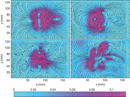
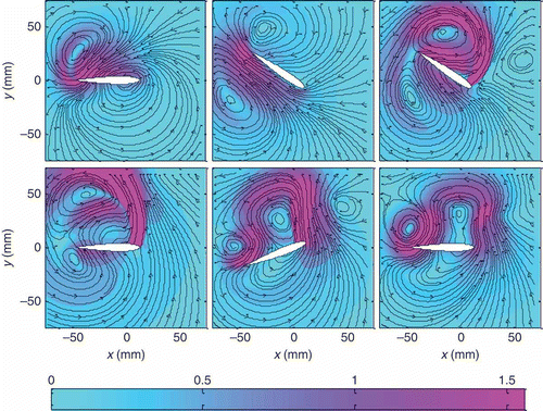
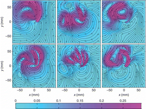
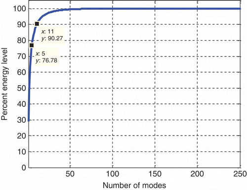
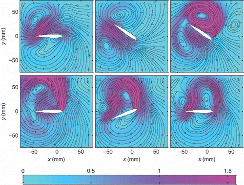
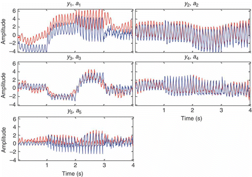
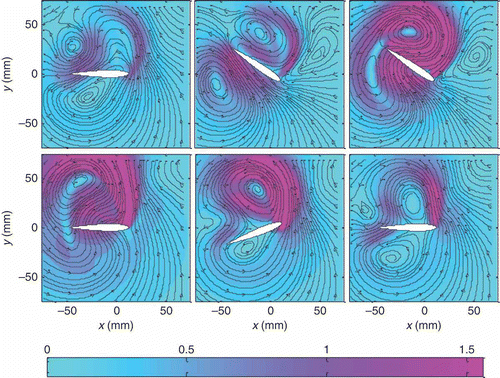
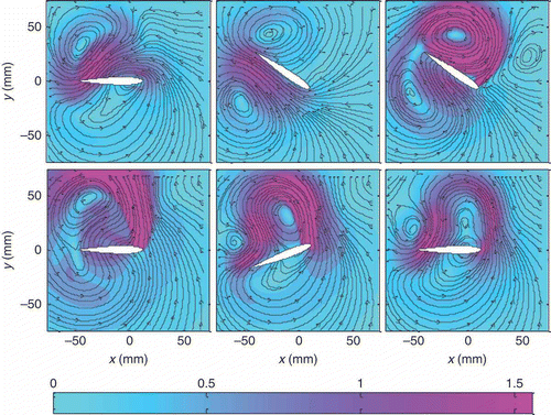
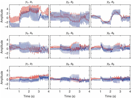
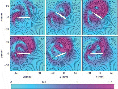
In this section, we attempt to construct a dynamical model for the case where the airfoil is pitching fast and is actuated through a slit on the airfoil (see ). We are unable to employ PIV for this case as our experimental set-up lacks actuators and cannot provide fast pitching. Instead, we use FLUENT to carry out CFD simulations as described in Section 2.2, using the actuation input shown in The velocity snapshots obtained from these simulations are shown in The POD modes obtained from these snapshots can be seen in The percentage of flow energy retained by choosing a given number of POD modes to represent the flow is plotted in For the sake of example, we shall consider two cases, namely using 5 and 11 POD modes to represent the flow, which correspond to roughly 77% and 90% of the flow energy, respectively. For the case of five POD modes, the reconstructions using the time coefficients corresponding to the modes are given in Comparing with , one can see that five modes capture the general trend of the flow, but there are some local differences in the details. Thus, this choice would be appropriate when an approximate model would suffice for the purposes of the application. Proceeding with the SI, as described in Section 2.4, results in a model of order 70, the outputs of which are shown in comparison with the POD time coefficients in It can be seen that the dynamical model built by SI captures the general trend in the time coefficient trajectories, but there are some variations and departures for certain parts. This is to be expected as the SI-based model is only a simple finite-dimensional linear approximation of the forms (13) and (14) to the non-linear, complicated and infinite-dimensional NS PDEs. The reconstructions of the flow snapshots using the SI model outputs are shown in As expected, the reconstructions are consistent with the CFD snapshots () and POD reconstructions () in capturing the general characteristics of the flow, but one can observe local differences in some areas.
For the case of 11 POD modes, the reconstructions using the time coefficients corresponding to the modes are given in Comparing with , one can see that 11 modes capture the general trend of the flow, but there are some local differences in the details. However, the approximation is better than the 5-mode case () because 11 modes capture more of the flow energy. This choice would be appropriate when a more accurate and approximate model would be needed for the purposes of the application. Proceeding with the SI, as described in Section 2.4, results in a model of order 80, which is higher than that obtained for the five-mode case. This is to be expected because the model is required to represent six additional outputs compared with the previous case. The outputs of the model are shown in comparison with the POD time coefficients in It can be seen that the dynamical model built by SI captures the general trend in the time coefficient trajectories, but there are some variations and departures for certain parts. This is an anticipated outcome because the SI-based model is only a simple finite-dimensional linear approximation of the forms (13) and (14) to the non-linear, complicated and infinite-dimensional NS PDEs. The effect of these complications on the model accuracy may be easy or hard to fix and requires further analysis. For instance, one can observe a low-frequency drift in the responses in , which suggests that the model may be cured with a mean-flow dependent linear parameter-varying approach. The non-linearities may also come from higher frequencies, in which case refined models are needed. Although such an additional analysis was not performed for this particular work, we direct the interested reader to refer References [Citation42–44] for details regarding these advanced modelling strategies. The reconstructions of the flow snapshots using the SI model outputs are shown in As expected, the reconstructions are consistent with the CFD snapshots () and POD reconstructions () in capturing the general characteristics of the flow. One can still observe local differences in some areas, but the situation is an improvement over the five-mode case (see ).
4. Overall comparison of all results
As a final overall quantitative comparison of all the scenarios considered, we define the following percent mean reconstruction error metric:
where U are the original measurements (from PIV or CFD), are the reconstructed velocities (using POD coefficients or SI model outputs),
is the vector norm and
is the averaging operator that computes the mean value over all the nodes in the flow domain and all the snapshots. The values obtained are tabulated in . From the table, it can be seen that for the unforced slow-pitching wing data from PIV, selecting 100 modes captures almost all (98.93%) of the flow energy, as a result of which the POD reconstruction is very accurate and the SI reconstruction error is also acceptable. Note that the SI reconstruction error will always be higher because the SI model approximates the POD coefficients; hence, it is an approximation of an approximation. For the forced fast-pitching wing data obtained from CFD, the SI model reconstruction error is significantly higher for the 5-mode case compared with the 11-mode case. The former case might be preferable when high accuracy can be compromised to obtain a low-order model, in which case one would settle for a model representing only the general trends of the flow. However, in order to obtain an accurate model, one must increase the number of modes and hence agree to dealing with a higher order model.
Table 2. Comparison of modelling errors for the cases considered throughout the article
It is also worth noting that the slow flapping case is based on experimental PIV data, whereas the fast flapping case is based on CFD data. We predict that for the experimental case, the imperfections in the physical set-up, the numerical errors in post-processing and the unmodelled dynamics of the flow create more random and unpredictable behaviour in the snapshots compared with the CFD case, which contribute to the necessity of using a considerably high number (100) of POD modes for an accurate representation.
5. Conclusions, discussions and future works
In this article, a modelling approach to represent the dynamical behaviour of a pitching airfoil is considered. The method is based on experimental PIV images and CFD snapshots, which are processed to obtain the instantaneous velocity field of the flow. The location and orientation of the airfoil is determined using image processing and this information is used to fill the region in the images corresponding to the airfoil with proper velocity data. These post-processed images are used to compute the POD modes and time coefficients of the system. A proper number of POD modes and time coefficients are selected to capture a desired amount of the flow energy and then a discrete-time state-space model is fit to these time coefficient trajectories using subspace SI methods. The method proposed is illustrated in two example problems: (1) building a dynamical model for a slow-pitching non-actuated airfoil from PIV measurements and (2) building a dynamical model for an actuated fast-pitching airfoil from CFD snapshots. It was observed that the models built can successfully capture the general trends, but there are some local deviations, which are to be expected because the models are only approximations to the complicated non-linear physics governing the flow process.
The main original contributions of the article can be summarized as follows:
| 1. | A novel technique for the modelling of the flow over flapping wings is proposed and proved to work through PIV experiments and CFD simulations. The novelty of the technique is due to its fusion of POD and SI to produce reduced-order models for flows over flapping wings. Such an approach does not exist in the current literature for flapping wings. | ||||
| 2. | The technique can be applied to both unforced and forced flows, and it is able to generate the contribution of the actuation as a separate term in the dynamical model. This is also an important originality because the flow modelling approach in many studies utilizes only the actuated snapshots in the modelling process and does not make use of the actuation input beyond the point where the snapshots are generated. In this study, we provide the actuation input explicitly to SI so as to force the identification of a relation between the actuation and the flow behaviour. This produces reduced-order models in which the control term is explicit, which is the standard structure to which control design can be applied in future works. | ||||
The models obtained can be utilized for both analysis and design purposes. One can employ the models to predict the flow behaviour as a result of wing flapping. This could be useful as the flapping behaviour could produce unwanted flow structures such as the shedding of vortices, the magnitude of which could grow quite intense and cause structural damages to the wing structure as well as to the frame of the air vehicle. Certainly, the eventual goal of obtaining models representing flow dynamics is to utilize them in control design. This is the reason why the second case (i.e. the fast flapping case with actuation) was included as this case enabled us to study the effect of actuation to the flow. Understanding this effect will allow us to find mechanisms to suppress unwanted flow dynamics such as vortex shedding. It is also possible to measure/compute the lift and drag forces on the wing, set these as the output of the model and utilize the actuation input to improve these forces dynamically.
At this point, it should be admitted that the scenarios considered in this article have relatively low Reynolds numbers (in the context of flow over airfoils) of 188 and 4768, respectively. Very high Reynolds number flows with lots of turbulence would be quite challenging to model because the flow behaviour would be highly random and difficult to capture with deterministic models. In these cases, one might have to resort to more statistical approaches and/or attempt to find a way of incorporating additional modes to capture the effects of turbulence. Despite this limitation, we believe that the discussion in the article is still quite useful because many of the real-life wing flapping applications take place at relatively low Reynolds numbers. These include living creatures such as birds, bats and insects as well as most human-made MAVs [Citation45].
It is also worth mentioning that the modelling technique introduced in this article is only weakly dependent on the particular flapping wing application in the sense that it was applied to the data collected for this particular case. However, whether the problem is a pipe flow, cylinder wake, flow around the wings of an airfoil or that of a submarine hull, the procedure for obtaining the dynamical model is all the same. We therefore believe that the modelling technique proposed will be of interest to a large community of engineers and scientists working on a variety of flow control problems.
Our future research directions include applying the method proposed to data from different PIV experiments and CFD simulations; using different SI techniques (including non-linear ones) to improve the dynamical models; devising methods to achieve further order reduction for the models resulting from SI and utilizing the models obtained in control of flow structures (vortex shedding) as well as critical forces (e.g. lift and drag).
Acknowledgements
The authors thank the Scientific and Technological Research Council of Turkey (TUBITAK) and the European Commission (EC) for supporting this work through projects 109E233 and PIRG-2008-GA-239536, respectively.
Notes
1. Note that this will result in different flow dynamics than that of Section 2.1, but this is not an issue for our purposes as we are not attempting in any way to study the consistency of PIV and CFD results. These methods are just tools to generate data for the modelling process, and the data collected from PIV and CFD will be used separately to generate two separate models; the former for the unforced slow-pitching airfoil and the latter for an actuated fast-pitching airfoil. Ideally, we would have preferred to generate PIV data for both; unfortunately, our experimental hardware is limited and cannot generate pitching velocities beyond a certain value. In addition, we currently do not have actuators installed on our set-up.
References
- Azuma , A. , Masato , O. , Kunio , Y. and Mueller , T.J. 2001 . Aerodynamic characteristics of wings at low Reynolds numbers, fixed and flapping wings aerodynamics for micro air vehicle applications . AIAA Prog. Astronaut. Aeronaut. , 195 : 341 – 398 .
- Fearing , R.S. , Chiang , K.H. , Dickinson , M. , Pick , D. , Sitti , M. and Yan , J. Wing Transmission for a Micromechanical Flying Insect . Proceedings of the 2000 IEEE, International Conference on Robotics & Automation . San Francisco , CA . pp. 1509 – 1516 . New York : Institute of Electrical and Electronics Engineers (IEEE) .
- Ho , S. , Nassef , H. , Pornsinsirirak , N. , Tai , Y.C. and Ho , C.M. 2003 . Unsteady aerodynamics and flow control for flapping wing flyers . Prog. Aerosp. Sci. , : 635 – 681 .
- Frauenfelder , M. 2006 . MAKE: Technology on Your Time , Vol. 8 , Sebastopol , CA : O'Reilly Media .
- Lentink , D. , Van Heijst , G.J. , Muijres , F.T. and Van Leeuwen , J.L. 2010 . Vortex interactions with flapping wings and fins can be unpredictable . R. Soc. Biol. Lett. , 6 : 394 – 397 .
- Kurtulus , D.F. 2008 . Ability to forecast unsteady aerodynamic forces of flapping airfoils by artificial neural network . Neural Comput. Appl. , 18 ( 4 ) : 359 – 368 .
- Kurtulus , D.F. , David , L. , Farcy , A. and Alemdaroglu , N. 2008 . Aerodynamic characteristics of flapping motion in hover . Exp. Fluids , 44 : 23 – 36 .
- Deng , X. , Schenato , L. and Sastry , S.S. 14–19 September 2003 . Model identification and attitude control scheme for a micromechanical flying insect , 14–19 September , Taiwan : International Conference on Robotics and Automation .
- Zbikowski , R. 2002 . On aerodynamic modeling of an insect-like flapping wing in hover for micro air vehicle . Phil. Trans. R. Soc. Lond. A , : 273 – 290 .
- Rowley , C.W. , Colonius , T. and Murray , R.M. 2004 . Model reduction for compressible flows using POD and Galerkin projection . Phys. D , 189 : 115 – 129 .
- Noack , B.R. , Afanasiev , K. , Morzynski , M. , Tadmor , G. and Thiele , F. 2003 . A hierarchy of low-dimensional models for the transient and post-transient cylinder wake . J. Fluid Mech. , 497 : 335 – 363 .
- Erbil , T.N. and Kasnakoglu , C. 2009 . Feedback flow control employing local dynamical modeling with wavelets . Math. Comput. Model. Dyn. Syst. , 15 : 493 – 513 .
- Wilcox , K. and Peraire , J. 2002 . Balanced model reduction via proper orthogonal decomposition method . AIAA J. , 40 ( 11 ) : 2323 – 2330 .
- Tran , H.T. and Ly , H.V. 2001 . Modeling and control of physical process using proper orthogonal decomposition . Math. Comput. Model. , 33 ( 1–3 ) : 223 – 236 .
- Bourguet , R. , Braza , M. and Dervieux , A. 2007 . Reduced-order modeling for unsteady transonic flows around an airfoil . Phys. Fluids , 19 ( 11 ) : 1 – 4 .
- Noack , B.R. , Morzynski , M. and Tadmor , G. 2011 . Reduced-Order Modelling for Flow Control , New York : Springer . ISBN: 978–3709107577
- Prasad , A.K. , Hopkins , L.M. , Kellya , J.T. and Wexler , A.S. 2000 . Particle image velocimetry measurements in complex geometries . Exp. Fluids , 29 : 91 – 95 .
- Raffel , M. , Willert , C. , Wereley , S. and Kompenhans , J. 1998 . Particle Image Velocimetry: A Practical Guide , New York : Springer .
- Scarano , F. and Riethmuller , M.L. 1999 . Iterative multigrid approach in PIV image processing with discrete window offset . Exp. Fluids , 26 : 513 – 523 .
- Daichin , W. Kang and Zhao , L. 2007 . PIV measurements of the near wake flow of an airfoil above a free surface . Sci. Direct J. Hydrodyn. Ser. B , 19 ( 4 ) : 482 – 487 .
- Druault , P. and Challiou , C. 2007 . Use of proper orthogonal decomposition for reconstructing the 3D in-cylinder mean-flow field from PIV data . C. R. Méc. , 335 ( 1 ) : 42 – 47 .
- Druault , P. , Guibert , P. and Alizon , F. 2005 . Use of proper orthogonal decomposition for time interpolation from PIV data . Exp. Fluids , 39 ( 6 ) : 1009 – 1023 .
- Ford , M.D. , Nikolov , H.N. , Milner , J.S. , Lownie , S.P. , DeMont , E.M. , Kalata , W. , Loth , F. , Holdsworth , D.W. and Steinman , D.A. 2008 . PIV-measured versus CFD-predicted flow dynamics in anatomically realistic cerebral aneurysm models . J. Biomech. Eng. , 130 : 021015
- Ranade , V.V. , Perrard , M. , Le Sauze , N. , Xuereb , C. and Bertrand , J. 2001 . Trailing vortices of rushton turbine: PIV measurements and CFD simulations with snapshot approach . Chem. Eng. Res. Des. , 79 ( 1 ) : 3 – 12 .
- Ravindran , S.S. 2000 . Reduced-order adaptive controllers for fluid flows using POD . J. Sci. Comput. , 15 ( 4 ) : 457 – 478 .
- Bleris , L.G. and Kothare , M.V. 2005 . Reduced order distributed boundary control of thermal transients in microsystems . IEEE Trans. Control Syst. Technol. , 13 ( 6 ) : 853 – 867 .
- Kowalski , M.E. and Jin , J.M. 2003 . Model-order reduction of nonlinear models of electromagnetic phased-array hyperthermia . IEEE Trans. Biomed. Eng. , 50 ( 11 ) : 1243 – 1254 .
- Gerhard , J. , Pastoor , M. , King , R. , Noack , B.R. , Dillmann , A. , Morzynski , M. and Tadmor , G. 2003 . Model-based control of vortex shedding using low-dimensional Galerkin models . AIAA Pap. 2003–4262, 33rd AIAA Fluid Dynamics Conference and Exhibit . June 23–26 2003 , Orlando , FL . Reston , VA : The American Institute of Aeronautics and Astronautics (AIAA) .
- Couplet , M. , Basdevant , C. and Sagaut , P. 2005 . Calibrated reduced-order POD-Galerkin system for fluid flow modelling . J. Comput. Phys. , 207 ( 1 ) : 192 – 220 .
- Rapun , M.L. and Vega , J.M. 2010 . Reduced order models based on local POD plus Galerkin projection . J. Comput. Phys. , 229 ( 18 ) : 3046 – 3063 .
- Dantec Dynamics, Particle Image Velocimetry Measurement Principles, 2010. http://www.dantecdynamics.com/Default.aspx?ID=1049 (http://www.dantecdynamics.com/Default.aspx?ID=1049) (Accessed: 18 June 2012 ).
- Galletti , B. , Bottaro , A. , Bruneau , C.H. and Iollo , A. 2007 . Accurate model reduction of transient and forced wakes . Eur. J. Mech. B/Fluids , 26 : 354 – 366 .
- Luchtenburg , D.M. , Noack , B.R. and Schlegel , M. 2009 . An introduction to the POD and Galerkin method for fluid flows with analytical examples and MATLAB source codes , Berlin : Tech. Rep. 01/2009, Berlin Institute of Technology .
- Kostas , J. , Soria , J. and Chong , M. 2002 . Particle image velocimetry measurements of a backward-facing step flow . Exp. Fluids , 33 : 838 – 853 .
- Uzol , O. and Katz , J. 2007 . Flow measurement techniques in turbomachinery . Springer Handb. Exp. Fluid Mech. , 14 : 919 – 958 .
- Bergmann , M. , Cordier , L. and Brancher , J.P. 2005 . Optimal rotary control of the cylinder wake using proper orthogonal decomposition reduced-order model . Phys. Fluids , 17 ( 9 ) : 097101
- Holmes , P. , Lumley , J.L. , Berkooz , G. and Rowley , C.W. 2012 . Turbulence, Coherent Structures, Dynamical System, and Symmetry , 2nd , Cambridge : Cambridge University Press . ISBN: 978-1-107-00825-0
- Sirovich , L. 1987 . Turbulence and the dynamics of coherent structures . Q. Appl. Math. , 45 : 561 – 50 .
- Ljung , L. 1999 . System Identification: Theory for the User , Upper Saddle River , NJ : PTR Prentice Hall .
- Van Overschee , P. and De Moor , B. 1996 . Subspace Identification for Linear Systems: Theory-Implementation-Applications , Dordrecht : Kluwer Academic .
- Larimore , W.E. 1996 . Statistical optimality and canonical variate analysis system identification . Signal Process. , 52 : 131 – 144 .
- Noack , B.R. , Schlegel , M. , Morzynski , M. and Tadmor , G. 2010 . System reduction strategy for Galerkin models of fluid flows . Int. J. Numer. Method Fluids , 63 ( 2 ) : 231 – 248 .
- Siauw , W.L. , Bonnet , J.-P. , Tensi , J. , Cordier , L. , Noack , B.R. and Cattafesta III , L. 2010 . Transient dynamics of the flow around a NACA0015 airfoil using fluidic vortex generators . Int. J. Heat Fluid Flow , 31 : 450 – 459 .
- Tadmor , G. , Lehmann , O. , Noack , B.R. and Morzynski , M. 2010 . Mean field representation of the natural and actuated cylinder wake flow . Phys. Fluids , 22 : 1 – 22 . 034102
- Shyy , W. 2008 . Aerodynamics of Low Reynolds Number Flyers , Cambridge : Cambridge University Press .
