Abstract
The use of Autonomous Underwater Vehicles (AUV) as robots for exploration and oceanology science has been a field of interest of several universities and research centres around the world. Researchers from the Universidad Central de Las Villas (UCLV) and the Hydrographic Research Center (HRC) have joined forces in the development of the HRC–AUV project. This article is aimed at displaying the calculation of the HRC–AUV dynamic model, based on low-cost sensors and a set at low-cost experiments. The model is developed to synthesize control algorithms, fault tolerance schemes and navigation systems. Dynamic behaviour and validation of the obtained model is evaluated by means of simulation and sea trials experimental data. Based on a simplified versions of the dynamic model, a heading and pitch/depth controls were implemented. Experimental results of heading and pitch/depth controls and a basic path following are presented.
1. Introduction
An Autonomous Underwater Vehicle (AUV) is a submarine that carries its own power source and a computer unit, running software and control solutions that allow the execution of a mission without human intervention [Citation1]. This research work is carried out by the Group of Automation, Robotics and Perception (GARP) of the Universidad Central de Las Villas (UCLV) and the Hydrographic Research Center (HRC). Both teams have developed an AUV for research purposes. The HRC–AUV (project and vehicle name) is a low-cost system [Citation2] and consists of several tasks such as AUV design and mechanical/naval construction, control architecture design, software and hardware implementation (including sensor integration), dynamic modelling, path planning and control of strategy implementation; all tasks are needed for the achievement of an autonomous behaviour of the vehicle.
From a control viewpoint, the 6 degree of freedom (DOF) non-linear model of the underwater robot, together with uncertainties in the hydrodynamic coefficients, makes underwater vehicles a challenging system to be modelled and controlled. Research solutions based on the vehicle dynamic model such as control algorithm [Citation3–6], fault tolerance schemes [Citation6,Citation7] and navigation systems [Citation8,Citation9] have great importance for robots moving through an unknown, unstructured and probably dangerous environment.
The HRC–AUV prototype is a cigar-shaped vehicle, with physical structure similar to HUGIN 4500 [8] or STARFISH [Citation10], although bigger. There is a strong tendency in the literature to use the cigar-shaped submarine developed by Fossen [Citation11] as a guide for modelling of underwater vehicles [4,Citation12]. This modelling technique was applied in a creative way in order to obtain the dynamic model of the HRC–AUV. Following this methodology, it was possible to obtain the dynamic model of the HRC–AUV. An important part of model coefficients is calculated from the vehicle geometric and inertial data. Nevertheless, there are other parameters associated with the viscous damping and the control inputs that can be only estimated through experimental tests. The creative interpretation by GARP of the method proposed by Fossen [11], the selection of the essential equations of underwater vehicles dynamic modelling, and the implementation of a set of experiments, performed with auxiliary equipment readily available, allow the presentation of a method for obtaining the dynamic model of a low speed, slender body AUV, that can be used by many scientific institutions. This systematized knowledge is the main contribution of this research.
Based on the HRC–AUV simplified dynamic model, a heading control and a pitch/depth control were implemented. As in other researches [3,5], classic proportional, integral and derivative (PID) controllers are used. First, the controller setting was found by simulation and after that it was tested in the HRC–AUV, using the same setting and showing good results. As a demonstration, responses to a step input in the set-point are presented. Graphical results of the path following over a 3 km trajectory on sea trials are showed.
This article is organized as follows. A brief description of the low-cost HRC–AUV is presented in Section 2. In Section 3, the general modelling concepts for the cigar-shaped AUV are explained. In Section 4, the linear models around an operation point are presented, divided into subsections, longitudinal, lateral and navigation subsystems. The dynamic model of the HRC–AUV is presented in Section 5. In Section 6, the general modelling of the main environmental disturbances is presented. The effectiveness of the model calculated is demonstrated in Section 7. Finally, Section 8 shows the conclusions.
2. General description of the HRC–AUV
The HRC is an institution with several years in the research and development of vessels. The mechanical design and naval construction of the HRC–AUV is the newest experience related to underwater vehicles. A general overview of the structure and main parameters is shown in , and
Table 1. Geometric and inertial values of the HRC–AUV
The vehicle design was created to carry out missions that may be developed from shallow to medium depth waters. The actuator system of the vehicle is composed of one propeller and two control stern rudders (aft rudder and stabilizing fin), all electrically driven. The system has three operation environments [2]: tele-direction (in surface), automatic close-loop operation to follow desired heading/depth and automatic autonomous operation with inertial navigation assisted with a mathematical model. This last topic is not addressed in this publication because it will be part of a future article.
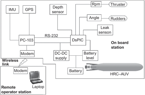
The general hardware architecture of the system is quite basic and open, featuring all the necessary elements to achieve a controlled operation. A more detailed view is shown in The segment hardware architecture on board is composed of two computational units and one power unit [2]. The computer units are an Advantech® PC-103 industrial computer and an embedded system based on a Microchip® DsPIC 30F4013.
As shown in , the hardware architecture is similar to the one proposed by other authors in the field [8,10], being the most notable differences the use of less quality sensors for the inertial navigation system (INS), and the non-use of other aiding sensors like a doppler velocity log (DVL) and an acoustic doppler current profiler (ADCP). It is valid to remark that the open architecture of the system allows the inclusion of the sensors mentioned or other needed for a particular application through several available communication ports [2]. The sensors installed on board the HRC–AUV at the reported experiments can be listed as follows:
| – | Inertial Measurement Unit (IMU): MTi from Xsens. It is used for accurate real-time attitude and orientation of the vehicle. Capital sensor of the INS. | ||||
| – | Depth: Cerabar T PMP 131 from Endress + Hauser, analogue sensor. It is used for determining the operation depth of the AUV. Aid to the INS. | ||||
| – | Battery level: analog sensor. It estimates the status of the battery levels. | ||||
| – | Leak: digital sensor. In order to detect any water leakage, these sensors are located inside the lower part of the hull. | ||||
| – | Rudders angle: MLO – POT – 225 – TLF from Festo, analogue sensor. It provides the true position of the rudders. | ||||
| – | Thruster rpm: digital sensor. Revolutions of the main propulsion thruster. | ||||
| – | GPS: XL12 from Garmin, digital sensor. It provides accurate information on the status of the vehicle, given in latitude, longitude, speed and height. (It is used only to surface navigation.) depicts the error and precision specifications of GPS. Table 2. GPS Garmin XL12 measurement performance | ||||
This hardware architecture is sufficient for the identification, control and dead-reckoning navigation tasks, according to the following work assignment.
| – | DsPIC unit deals with all analogue measurements related to depth, heading control, rudders angle, propulsion parameters, battery levels and leak sensors. This unit is also entrusted with the heading and depth control of the HRC–AUV. | ||||
| – | PC-103 unit deals with all digital measurements related to position and attitude estimation from INS/GPS relation. This unit also runs the navigation and communication software. | ||||
| – | Power unit composed of DC–DC platform that supplies all the voltage needed by the HRC–AUV electronics and sensors, PWM driver that manages the rudders angle and one on/off system for the main propulsion thruster (directly connected to the batteries). | ||||
The remote segment in terms of hardware is composed of a laptop (P-IV with at least 256 MB of RAM) and a wireless link [2].
The software running at the remote operator station was developed in ‘C#’ and features several services:
| – | Monitoring service: Through this service, the user can visualize the different variables representing the state of the vehicle and monitor the HRC–AUV surface navigation. | ||||
| – | Control service: This service allows user to visualize through graphics, the state of the measured variables, and compare them with the desired ones, and it also allows to display and change the controllers gains. | ||||
| – | Tele-operation: Through the tele-operation service, the user can drive the system manually by changing the rudders' depth and heading angles. | ||||
| – |
Identification service: The identification service includes two sub-services, one that offers tools for the identification of the lateral system (see Section 4.2) and another one for the identification of the longitudinal system (see Section 4.1). Both have a slider that can be used to vary the angles of deflection of the respective rudders and record the system response. For the lateral subsystem, we variate | ||||
| – | Trajectory service: This service allows the user to set the desired way points at which the vehicle must arrive. The trajectory service gives the possibility of changing the distance once the vehicle reaches the desired point. | ||||
It is valid to notice that all these services are updated through a wireless link, only available in surface operation [2].
3. Dynamic modelling of 6 DOF for an AUV
The modelling method chosen in this work is a geometrical-based analysis. It consists mainly of finding the parameters of the model, which have been well defined through physical laws describing the motion of a rigid body on a liquid environment.
An AUV can be dynamically considered as a rigid solid with : three coordinates for the movements of displacement and other three for the movements of rotation, presenting a highly non-linear and coupled dynamic relationship.
Achieving an accurate dynamic model is necessary for AUV's behaviour because many methodologies of regulators synthesis and tuning require a mathematical model. In addition, in the Navigation case, the dynamic model can be used.
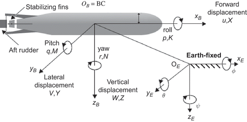
The motion of a submarine at sea is described with respect to an inertial reference system. It is usually assumed that the acceleration of the planet surface produced by the rotation of the Earth does not affect the motion of low-speed marine vehicles. Thus, a reference system located on the Earth can be considered as an inertial frame. depicts the coordinate systems and the definition of translation and rotation variables of the vehicle.
Representing the motion of a vehicle would take six independent coordinates. Three coordinates are used to describe the translational motion on the axes ,
and
(forward, lateral and vertical displacement, respectively), relative to a coordinate system OB located on the vehicle. The other three coordinates describe the rotational motions (roll, pitch and yaw, respectively) that belong to the inertial coordinate system OE located on the Earth. summarizes the nomenclature used to describe the mobile motion, forces and moments. This is the recommended standard notation for use in maneuver applications and control of submarines [Citation13].
Table 3. Notation for AUVs
The origin of the coordinate system of the submarine is normally chosen to coincide either with the gravity centre (GC) or with the buoyancy centre (BC), taking for granted that the selected one is located in some of the symmetry planes. On the HRC–AUV, the OB frame origin coincides with the point BC.
The linear and angular velocities, as well as forces and moments, are often referenced to the coordinate system OB. However, the inertial reference system OE is used so as to represent the attitude of the mobile. The velocity and attitude vectors are defined as follows:
The velocity and attitude vectors, shown in EquationEquations (1)(1) and (Equation2
(2)), can be translated between the two frames of interest (body fixed and earth fixed) through the transformations of Euler angles [1,11].
where
where ,
and
, noticing that
.
The equations representing the vehicle motion in the three-dimensional space can be obtained from the conservation laws of linear and angular moments applicable to an inertial reference system. Fossen [11] writes that Newton's second law can be expressed for any coordinate system fixed to a rigid body as:
Equation (6) can be represented as:
where is the inertial matrix including the added mass,
is the Coriolis matrix including the added mass,
is the damping matrix,
is the vector of gravitational/buoyancy forces and moments and
is the vector of control inputs.
3.1. Calculus of the rigid body, hydrodynamics and hydrostatics terms
3.1.1. Rigid body terms
To calculate the matrices that cluster the rigid body terms, it is necessary to define the position of OB, which is usually placed on the CB of the vehicle. The distance between GC and BC is defined as . HRC–AUV is a cigar-shaped submarine in which
(see ), therefore, in these conditions, matrix
can be calculated as:
and matrix as
where m is the mass of the vehicle that is assumed to be uniformly distributed, and I
is the inertia matrix referred to the body-fixed reference system.
3.1.2. Hydrodynamic terms
The hydrodynamic forces and moments are produced by the pressure of the surrounding fluid on the vehicle (effect known as added mass), and the viscous damping [Citation14].
The AUV-added mass can be calculated from diagrams of CAD/CAM systems used in vehicle design software as input to hydrodynamic calculations [3]. It can also be calculated with a good approximation by taking advantage of the vehicle's geometry.
A method for calculating the added mass terms using an approximation to an ellipsoidal body with uniform mass distribution already exists [11]. However, the AUVs normally have cylindric geometry and only the front and aft parts seem to be ellipsoidal. Due to this difference, the standard procedure consists of defining the body parameters and finding its equivalent prolate ellipsoid [12].
The equivalent ellipsoid parameters are based on the inertia moments of the AUV, approximated to those in a uniformly distributed mass cylinder, where inertia moment is given by
assuming r as the actual radius of the AUV. The moment of inertia
corresponding to the prolate ellipsoid is considered to be equal to that one of the cylinder. This moment of inertia is given by
, assuming
as the radius of the widest part of the ellipsoid. Moreover, the equivalent cylinder volume is assumed to be equal to the ellipsoid volume. With these assumptions, all the parameters of the ellipsoid can be found.
Once the equivalent ellipsoid has been defined, using the symmetry of the vehicle configuration, the matrices and
have the following expressions:
and
The matrix parameters can be obtained by setting the ellipsoid mass
, and its widest and largest radii as (b) and (a), respectively. Fossen [11] gives the necessary equations to calculate the parameters of the ellipsoid. It can be noticed that
Several authors use a similar procedure to the one described in this research [12,Citation15].
The most complex task in the AUV modelling process is the determination of the damping terms. In the case of underwater vehicles moving at high speed, damping is highly non-linear and coupled. However, AUV movement normally happens at medium or low velocities. On the other hand, the assumption that the vehicle behaves with a decoupled motion is a good approximation.
As a result, diagonal structures with only linear and quadratic damping terms are obtained, as shown:
It is noticed that
For the control model, a good approximation would be assuming that this effect is produced mainly by the action of viscous forces over the vehicle, and it can be described as it was shown before. It is evident that at a low speed motion the higher order terms can be neglected, thereby remaining:
In the case of the navigation model, at least the term has to be calculated, assuming as zero the remaining parameters of
. It is common to assume that when the geometry of the vehicle is similar to a cylinder:
For a cylindric shape rigid body moving near to the surface, the following expression is valid [11]:
where represents the drag coefficient of the front plane, which can be considered to be constant all over the vehicles longitude L.
For an AUV with these characteristics, as it is the HRC–AUV's case, it can be expressed as:
The following equation for calculation is recommended [16]:
where , because the relative damping ratios
and
for marine vehicles are quite small [Citation16].
3.1.3. Hydrostatic terms
The hydrostatic forces describe the weight–buoyancy relation manifested in any solid located in a liquid environment [14]. The gravitational force acts at the centre of mass GC, meanwhile the buoyancy force acts at the BC.
Several AUV projects, including the HRC–AUV, are designed with null buoyancy, which implies that weight is equivalent to buoyancy . Furthermore, the distance between GC and BC is
(see ). With these considerations, it can be said that:
3.2. Actuators modelling
The control forces produced by propellers, aft rudders and stabilizing fins, can be described as:
where k is the force coefficient and is the control input depending on the considered actuator, see
Table 4. Actuators and control variables
The forces and moments over the six DOFs produced by the force vector can be described as:
where is the vector that describes the moment arm related to the actuators' location with respect to OB's origin [Citation17]. The actuators of HRC–AUV can be perfectly aligned with OB origin, which coincides with CB of vehicle. It can be said that
and
.
The propeller force can be described as [11]
where n represents the motor's revolutions and the term depends on the propellers' diameter D and on the density of the water
.
For describing the relation between the actuators and the forces or moments, the following equation is used:
where is the thrust configuration matrix. Thereby, the control force can be written as
with control inputs and the force coefficient matrix
.
From EquationEquations (25(25)) and (Equation26
(26)), the following equation is obtained:
If the vector's values
r
in EquationEquation (27)(27) is replaced, taking into account
, the next equation is obtained:
The gain values are estimated performing experimental tests.
4. Linear dynamic model
Due to the vehicle's symmetry and its model's low coupling, it is common to divide the 6 DOF equations of motion (7) into two decoupled subsystems, or poorly assembled, of 3 DOF used for controlling the vehicle in OE's x–z and x–y planes [16].
| • | Longitudinal subsystem: states | ||||
| • | Lateral subsystem: states A third subsystem of 3 DOF is used for the navigation [8]. | ||||
| • | Navigation subsystem: states | ||||
4.1. Longitudinal subsystem
It is assumed that the variables , p, r and
are small, according to EquationEquations (4)
(4) and Equation(5)
(5), being the depth kinematic relationship:
From the EquationEquations (9)(9) and (11), assuming that
and noticing that the second-order terms related to
, w, p and r are small,
can be approximated as follows [16]:
On this basis, from the EquationEquations (8)(8), (Equation10
(10)), (Equation16
(16)), (Equation21
(21)) and (Equation29
(29)), the dynamic equation of the AUV, described through states
and
, is as follows:
This is the basic model for the control of velocity u and pitch/depth (states ). If the forward speed is stable
, it can be eliminated from the longitudinal equations of motion [16]. Under these conditions, the model is simplified to:
Moreover, if the pitch and depth loops become independent, it can be expressed that ; if
is small enough, then
. Therefore, the dynamics of pitching remains as the linear equation:
From the EquationEquation (28)(28), the following relationship is obtained:
On this basis, the transfer function between the stabilizing fin angle and pitch
is:
In addition, the relationship between the pitch angle and depth (z), considering the described linearization conditions:
4.2. Lateral subsystem
It is assumed that the variables u, w, p, r
and
are small, according to EquationEquations (4
(4)) and (5), leaving the lateral kinematic relationship as:
From the EquationEquations (9(9)) and (Equation11
(11)) and assuming that
,
can be calculated as [16]:
On this basis, from the EquationEquations (8(8)), (Equation10
(10)), (Equation17
(17)), (Equation21
(21)) and (Equation37
(37)), the dynamic equation of the AUV left to the states
and
is as follows:
For vehicles, where and p are small and the velocity
, the lateral EquationEquation (38
(38)) is reduced to:
The decoupled equation of ψ for small variations around operation point is
From the EquationEquation (28(28)):
The transfer function between the aft rudder angle and yaw or heading angle as it is also called, ψ, is
4.3. Navigation subsystem
To guarantee the trajectory tracking in a plane parallel to the plane of OE, it must be established a 3-DOF model which force vector according to is
, while its velocity vector remains
.
Under these conditions and using the EquationEquations (8(8)), (Equation9
(9)), (Equation10
(10)), (Equation11
(11)), (Equation16
(16)) and (21), the following equation is obtained:
noticing that according to the EquationEquation (28(28)):
Normally, the dominant trajectories are straight lines between turns, with u being the really significant component of the velocity vector. In this case, both lateral displacement and pitch angle are small, thus, it can be deduced a 1-DOF model for navigation from the EquationEquation (43(43)) [8], assuming
and
, the result is
The parameter belongs to the damping matrix and is estimated through experimental identification.
5. Numerical values of the HRC–AUV dynamic model
In this section, all values of model parameters are obtained according to the geometric structure, inertial information and a set of experiments carried out.
5.1. HRC–AUV’s inertial matrix, Coriolis matrix and hydrostatic terms
The HRC–AUV is a cigar-type submarine, completely symmetrical in the x–z plane, with good symmetry in the y–z plane and quasi-symmetric in the x–y plane. The HRC–AUV's geometrical and inertial values are presented in These values were estimated from the modelling of the vehicle using the Autodesk Mechanical Desktop®.
The calculation of the added masses comes from the prolate ellipsoid approximation. Using the EquationEquations (12(12)), (13), (14) and (15), the following values can be reached:
,
,
and
The M matrix according to the EquationEquations (8(8)) and (10) is
while the matrix , according to the EquationEquations (9
(9)) and (11), is
The vector of gravitational and rotational moments, by EquationEquation (21(21)), has the form:
On the other hand, the parameters of matrix and the gains of
vector are estimated through experimental identification.
5.2. HRC–AUV's damping matrix and Actuators model
In order to complete the dynamic description of the HRC–AUV, the matrix parameters and the actuators model are still unknown. Based on the linear models presented in Section 4, some experiments are developed so as to obtain the missing data. The experiments, that will be detailed in this section, could be done using simple auxiliary equipments. Moreover, these experiments were carried out using the architecture of software and low-cost hardware of the HRC–AUV [2].
5.2.1. Lateral subsystem
The simplified model between the aft rudder angle and yaw or heading angle (ψ), stated in EquationEquation (42
(42)), is
Based on an open loop scheme, some step variations in the aft rudder position () are manually introduced. Using the software possibilities (identification service) [2] (
) and the Rate Yaw Output (
) are recorded. The input
and output, signals are processed in the ‘ident’ toolbox of MATLAB® (a product of MathWorks, Inc.). According to the EquationEquation (42
(42)), the dynamic model is estimated using the ‘Process models technique’.
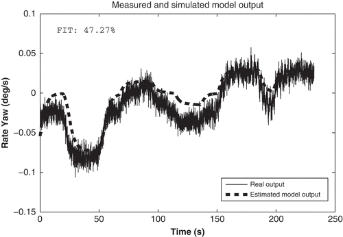
depicts the output of the model over the original measurement. The model is evaluated according to curve fitting parameter, fit. It is a statistics comparisons between the output of the model and the experimental output of the system, according to ‘ident’ toolbox of MATLAB®. In the evaluation process almost a of fit is achieved.
The calculated model through an experimental identification, similar to the structure of EquationEquation (42(42)), is the following:
Substituting EquationEquation (46)(46) in EquationEquation (42)
(42), it is possible to obtain:
Noticing that the value of is known, we obtain:
Knowing these values and using the EquationEquations (18)(18) and Equation(19)
(19), the following values are obtained:
then from the EquationEquation (41)(41), the values of
and
can be calculated as
In this moment, we have completed the dynamic model of 2-DOF lateral subsystem, EquationEquation (39)(39).
5.2.2. Longitudinal subsystem
From EquationEquation (34)(34), it is possible to obtain the simplified model between the stabilizing fin angle
and pitch
. The only term that remains unknown is the value of
. In order to find it, we followed the statements of Åstrom and Hägglond [Citation18], using a relay feedback scheme. In this type of scheme, a limit cycle of amplitude (a) and frequency (
) is produced. If d is the relay amplitude, the first harmonic of the square input signal has amplitude
. Leading to the EquationEquation (47)
(47)
This limit cycle occurs on the interception point of both, the Nyquist curve of the longitudinal simplified subsystem and the descriptive function, being equals their modules and phases at .
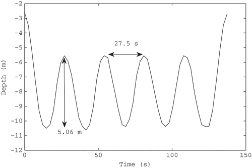
To reproduce these conditions, an experiment was conducted, in which the stabilizing fin angle was managed through a two-position relay at cruiser speed of
. The system command is approximately a square signal of amplitude
, storing the achieved depth values Z () (procedure similar to [Citation19]). This experiment satisfies the assumptions of ‘process under relay feedback’.
Then, at developing EquationEquations (34)(34) and Equation(35)
(35), it is possible to obtain that:
Placing the obtained values of rad/seg and
(), in (47) and (48), it is possible to obtain:
then from EquationEquation (33)(33):
In this moment, we have completed the dynamic model of 2-DOF longitudinal subsystem (EquationEquation (31)(31)).
5.2.3. Navigation subsystem
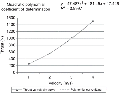
In order to complete the damping term of the navigation subsystem equation, a sea test was made towing the AUV at different constants' velocity values . The tow force needed for achieving each value of u is registered through a dynamometer. The registered force is equivalent to the registered force is equivalent to the forward movement resistance, which is equal to the thrust supplied by the propeller
when the AUV moves at the constant given velocity.
In , the curve fitting analysis of the registered data is showed. The experimental measurements of thrust versus u are showed in circles, and in continuous line is the correlative polynomial approximation.
Using EquationEquation (49)(49), it is possible to find the linear and quadratic terms of damping matrix, (EquationEquation (16)
(16)).
These parameters are very important for the navigation subsystem presented in Section 4.3.
On the other hand, when substituting the cruiser velocity in the polynomial of the EquationEquation (49)
(49) and considering the independent terms like viscosity friction, it is obtained that
with this value and the EquationEquation (24)(24), it can be ensured that at cruiser velocity and consequently propeller revolution set at
Finally, from the EquationEquation (20)(20), the value of
is obtained as
.
Then, according to the EquationEquation (17)(17),
meanwhile the vector gain matrix, according to the EquationEquations (33)
(33), Equation(41)
(41) and Equation(44)
(44), lays as:
makes a resume of all the terms used in the model.
Table 5. Resume of HRC–AUV estimated and identified parameters
6. Simplified model of main marine disturbances
Waves and ocean currents are the main disturbances that affects underwater vehicles during navigation. EquationEquation (7)(7) can be rewritten taken into account the waves and ocean currents as:
where represents the forces and moments related to waves and the relative speed to the currents represented by (
).
The literature reports a method [11] that allows to obtain the mathematical model of the disturbances. The effect of the waves and the marine currents is included in the general model of 6 DOF. It allows to ensure better results in the HRC–AUV positioning system.
6.1. Wave model
The forces and moments resulting from the wave are represented by the vector in the navigation system. The generated waves by the wind can be represented by a frequency spectrum. The high-frequency rises appear when the sea presents small crests and a smaller frequency rises occur when there are high crests at the sea. Waves are represented by summing wave components.
The Spectrum JONSWAP (Joint North Sea Wave Project) [11] is used to represent the waves generated by the wind in those marine zones, where the sea presents finite depth and limited area. The spectrum density is in function of the wind speed V to 10 m of altitude above the sea level and the geographic distance until the coast L [11]. These physical magnitudes can be measured and corrected by the operator from an earth station.
with
where represents the modal frequency, g is the gravity constant and
and
are constants.
It is necessary to count on a linear approach of the spectrum that can be included in the control loops. In such sense, it is possible to obtain a second-order transfer function , according to Gaussian white noise named
, and it returns back the model of the waves.
The transfer function is represented as:
where
is a constant that describing wave intensity and
represents the damping coefficient, generally of value 0.1.
The wave linear model is simulated bias Simulink–MATLAB as component of the vehicle model.
6.2. Simplified model of ocean currents
The effect of the ocean currents is added to the model of 6-DOF vehicle through term (relative speed) (EquationEquation (50)
(50)). The relative speed is defined as:
where being the speed vector of the vehicle (EquationEquation 1
(1)) and
the speed vector of the currents referred OB, considering that the currents do not generate rotational movements on the vehicle.
The speed components referred OE are related to the
by two angles: the attack angle
and the lateral displacement angle
. This investigation only takes into account a bi-dimensional analysis of currents, that is why the components are described according to average current speed
and
:
In order to obtain the speed component equations of the marine currents refered to OB, the Euler angle transformations and the trigonometrical identities are applied.
The currents can be integrated into the model of 6 DOF and its influence can be simulated in Simulink–MATLAB, which allows to know current affectations over the vehicle. Next section will present the results obtained by means of simulation and real experiments of the dynamic behaviour of the HRC–AUV considering the effect of the surge and the marine currents.
7. Performance of the HRC–AUV dynamic model
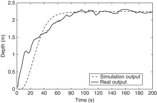
The model and its simplifications (submodels) allow to undertake the tasks required for an autonomous vehicle conception. In order to validate this assertion, the results obtained during several sea trials of the HRC–AUV throughout 2010 are presented. First, the full 6-DOF non-linear model (plus main marine disturbances) is tested from the data collected on several experiments (control inputs and disturbances). This model is validated with the experimental outcomes showing the parity between the model predicted outputs and the real ones. Based on the lateral model, stated in Section 4.2, the heading control is designed. The response to step input in the heading set-point and a general heading accuracy over a 3-km maneuvering trajectory are presented as a result of this design. Next based on the longitudinal model, stated in Section 4.1, the depth/pitch control is designed. The response to step input in the depth set-point is also presented. At last starting from the navigation model, stated in Section 4.3, a basic path following algorithm was implemented.
At present, this 6-DOF non-linear model is the base of two ‘model-aided’ researches, one regarding fault tolerance and the other model aided inertial navigation. These parallel researches are developed by GARP with encouraging results and will be presented in future articles.
7.1. Dynamic behaviour and validation of the HRC–AUV 6-DOF model
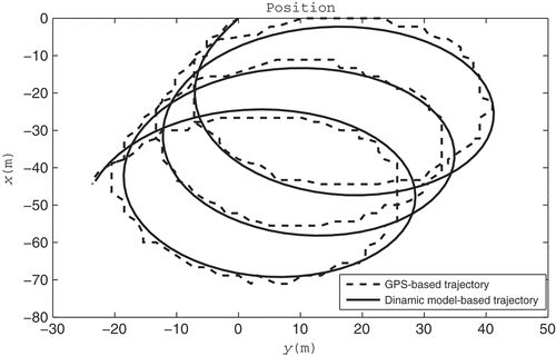
Validation of the HRC–AUV 6-DOF model accuracy in the presence of marine disturbances is obtained by means of evaluation and comparison to experimental data. In the first validation test, the model is provided with a set of parameter that matches a real experiment conducted on March 2010, as part of the identification process. The experiment consisted of applying a constant deflection angle to the aft rudder in a open loop scheme (not control system) and record the system response. The second validation test involves a bigger amount of data and maneuvers, obtained from a segment of the data collected on the path following experiment reported in Section 7.2.
The vehicle ‘true’ position is recorded by the GPS on board. The currents and the surge parameters are known from the experiment. Then by means of toolbox GNC of MATLAB [Citation20], it was possible to reproduce the experiment through simulation.
Initial conditions of the experiment are vehicle heading (yaw) , main propulsion thruster at 490 rpm and the aft rudder deflection angle was of –0.45 rad. On the other hand, marine disturbance were estimated as current speed
=
, current angle
, wave fundamental frequency
and
selected with value 0.5. depicts the vehicle's trajectory during the experiment (GPS based) and the trajectory achieved by the HRC–AUV 6-DOF model evaluation. It is valid to remark that main marine disturbances are included in the model.
The results indicate that the 6-DOF dynamic model behaviour of the HRC–AUV is quite similar to the observed one in the real experiment. The position mean error was of 2.9 m with a standard deviation of 1.74 m.
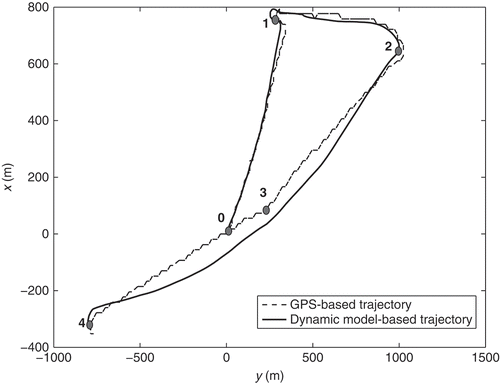
The second validation test takes the data collected during the experiment of path following. The experiment was carried out in July 2010 at North coast of Villa Clara province. The path following starts with a big turn to reach point (0) and then continues to each point in the schedule. The points are separated around 800 m.
depicts the vehicle trajectory during the path following experiment (based on GPS) and the trajectory described by the HRC–AUV 6-DOF model through simulation. The HRC–AUV 6-DOF model is initialized with the data from the INS and then operates with the data collected from the measurements of the rudders angle and the rpm sensor.
As can be observed, the output position of HRC–AUV 6-DOF model follows the trajectory described by the vehicle during the experiments. The principal errors appear at the moment the currents change direction during the time.
7.2. Heading control loop
The EquationEquation (42)(42) describes the simplified HRC–AUV's lateral dynamics (without taking into account coupling effects or marines disturbances). Based on this equation, the heading control structure is shown in The control scheme performance has been evaluated through simulation and more than 10 h of real experiments during sea trials on May and June 2010. The controller structure is a
, which fixed parameters:
,
and
.
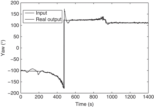
shows 33 minutes of HRC–AUV maneuvering with heading control system turned on. The data were collected during the path following experiments described in the previous section. The system response is affected by the waves' effect; however, it can be seen how the system is capable to respond to continuous step changes in the heading set point.
7.3. Pitch/depth loop
From EquationEquations (34)(34) and Equation(35)
(35), it is proposed as a control system, a cascade structure with a
controller for the pitch loop and a P controller for the outer depth loop represented in the scheme of
The simulated response of the system from step input of 2.25 m in the set-point of depth loop and the real response of the system achieved on the sea trials are shown in
8. Conclusions
In this work, the 6-DOF dynamic model of the HRC–AUV is presented. The necessary procedures for obtaining the non-linear model and its coefficients are introduced and discussed. This approach based on both geometric information and experimental identification can be generalized to other vehicles of similar shape. The effectiveness of the model was validated through comparison of the results obtained by simulation against the real ones of the experiments. From the full 6-DOF non-linear model, a linearization around the operation point is done, resulting in a linear lateral and longitudinal sub-models. These models are indispensable to determine the structure of the control regulators. As a example, a heading control and pitch/depth control based on the lateral and longitudinal models were implemented. After the tuning of the regulators, the general AUV performance was evaluated in sea trials following straight path and more complex trajectories. The technological challenge of working with low cost, low precision elements and simplified hardware schemes was satisfactorily beaten thanks to the use of a strong modeling effort and the correct selection of the experiments to be conducted. The model obtained will be used by GARP to implement fault tolerance strategies, more advanced versions of the control algorithm and model-aided inertial navigation technique. In the near future, GARP will consider whether it is convenient or not to carry out the transformation of model parameters (rotation and movement of translation) through Quaternions and will try to improve the performance of the dynamic model by means of the Kalman filter.
In the opinion of the authors, the obtained models and mostly the determination procedures are of great relevance to any researcher working in the field of AUV development. This result also represents a solid step in the evolution of the HRC–AUV project.
Acknowledgements
The authors thank the rest of GARP and HRC team members for their collaboration in the development of the sea trial.
References
- Fjellstad , O. 1994 . Control of unmanned underwater vehicles in six degrees of freedom a quaternion feedback approach . Doctoral thesis, NTNU, Norway ,
- Martínez , A. , Rodríguez , Y. , Hernández , L. , Guerra , C. and Sahli , H. 2010 . Hardware and software architecture for AUV based on low-cost sensors, in The 11th International Conference on Control, Automation, Robotics and Vision, ICARCV, IEEE Xplore, Singapore, December
- Kim , K. and Ura , T. 3-Dimensional trajectory tracking control of an AUV R-One Robot considering current interaction, in The Twelfth (2002) International Offshore and Polar Engineering Conference , 2002 Cupertino , CA : The International Society of Offshore and Polar Engineers .
- McEwen , R. and Streitlien , K. 2006 . Modeling and control of a variable-length AUV , Monterey , CA : Tech. Rep., Monterey Bay Aquarium Research Institute .
- Kim , K. and Ura , T. 2003 . Fuel-optimal guidance and tracking control of AUV under current interaction, in The Thirteenth International Offshore and Polar Engineering Conference , Cupertino , CA : The International Society of Offshore and Polar Engineers .
- Antonelli , G. 2003 . “ A survey of fault detection/tolerance strategies for AUVs and ROVs, in Advanced Robotic ” . In Springer-Verlag, Berlin/Heidelberg Edited by: Caccavale , F. and Villani , L. 109 – 127 .
- Ni , L. 2001 . Fault-tolerant control of unmanned underwater vehicles , Blacksburg , VA : Virginia Polytechnic Institute . Doctoral thesis
- Hegrenaes , O. , Hallingstad , O. and Jalving , B. Comparison of mathematical models for the HUGIN 4500 AUV based on experimental data, in The IEEE International Symposium on Underwater Technology , 2007 Tokyo : IEEE .
- Fauske , K.M. , Gustafsson , F. and Hegrenaes , O. July 2007 . “ Estimation of AUV dynamics for sensor fusion ” . In 10th International Conference on Information Fusion , July , 1 – 6 . Quebec : IEEE Xplore .
- Sangekar , M. , Chitre , M. and Koay , T.B. 2008 . Hardware architecture for a modular autonomous underwater vehicle STARFISH, in OCEANS, IEEE Xplore, Quebec, September 1 – 8 .
- Fossen , T. 1994 . Guidance and Control of Ocean Vehicles , New York : Wiley & Sons .
- daSilva , J.E. , Terra , B. , Martins , R. and deSousa , J.B. 2007 . Modeling and simulation of the LAUV autonomous underwater vehicle, in 13th IEEE IFAC International Conference on Methods and Models in Automation and Robotics , New York : IEEE Control Systems Society .
- SNAME . 1950 . Nomenclature for treating the motion of a submerged body through a fluid , New York : SNAME . Technical and Research Bulletin No. 1–5
- Antonelli , G. 2006 . Underwater Robots , 2nd , Vol. 2 , Milano : Springer .
- Gorset , J. 2007 . Nonlinear model-based control of slender body AUVs, Doctoral thesis , Norway : NTNU .
- Fossen , T. and Ross , A. 2006 . Nonlinear modelling, identification and control of UUVs.in Advances in Unmanned Marine Vehicles , Edited by: Roberts , G.N. and Sutton , R. Vol. 69 , 13 – 42 . London : Peter Peregrinus Ltd .
- Fossen , T.I. , Johansen , T. and Perez , T. 2008 . “ A survey of control allocation methods for underwater vehicles, in Underwater Vehicles ” . In InTech, Vienna Edited by: Alexander , V. Inzartsev . 109 – 128 .
- Åström , K. and Hägglund , T. 1995 . PID Controllers: Theory, Design and Tuning, , 2nd , NC : Instrument Society of America, Research Triangle Park .
- Miskovic , N. , Vukic , Z. and Omerdic , E. 2008 . “ Control of UUV s based upon mathematical models obtained from self-oscillations experiments, in IFAC Workshop on Navigation, Guidance and Control of Underwater Vehicles ” . In IFAC, Killaloe Edited by: Toal , D. , Omerdic , E. and Horgan , J. Vol. 2 ,
- Perez , T. , Smogeli , Ø.N. , Fossen , T.I. and Sørensen , A.J. 2006 . An overview of the marine systems simulator (MSS): a Simulink toolbox for marine control systems . Model. Ident. Control , 27 : 239 – 258 .
