Abstract
To study the effect of solid body contact deformation on the real contact area, various models are established. These contact models include a contact model between an elastic rough solid and a rigid flat one (E-R model), an elasto-plastic rough solid and a rigid flat one (P-R model), an elasto-plastic rough solid and an elastic flat one (P-E model), an elasto-plastic rough solid and an elasto-plastic flat one (P-P model). The effects of thermo-mechanical coupling and the heat flux coupling are considered in the model which is solved by ABAQUS software. The results show that the real contact area is not only determined by the normal load, but also affected by the contact deformation mode of solid body. The real contact area from the purely elastic model (E-R model) is much smaller than that from the other elasto-plastic model. But the real contact area obtained from the P-R model is the largest. No matter what kind of the solid body contact deformation is, at the moment of the abrupt change of sliding speed and of the hot spotting coming into being, the real contact area increases noticeably, and then varies in a small range during the constant frictional sliding process.
1. Introduction
The real contact area and contact region between rough surfaces play a key role in studying friction, wear and lubrication. For example, the adhesive force between two solids arises from regions where their atoms are close enough to interact, and the frictional force rises. The real size and geometry of these contact regions have influence on the stiffness, electrical and thermal conductivity of the contact interface, and are determined by the elastic and plastic deformation that extends below the surface of contact body. This kind of contact deformation may lead to local heating and wear, and limit the useful lifetime of sliding contact pairs (Pei et al. Citation2005).
To study the real contact area, many researchers have developed simplified normal contact models between a flat plane and single asperity or multi-asperities with regular shape (Kogut and Etsion Citation2002; Jeng and Wang Citation2003; Jamil and Kambiz Citation2005; Lin and Lin Citation2006; Robert and Itahak Citation2006; Ovcharenko et al. Citation2007; Carbone and Bottiglione Citation2008; Ovcharenko, Halperin, and Etsion Citation2008a, Citation2008b; Pugliese et al. Citation2008; Chung Citation2010; Li, Etsion, and Talke Citation2010; Caroline, Daniel, and Baietto Citation2012; Putignano et al. Citation2012). Using ANSYS software, Kogut and Etsion (Citation2002) performed a contact analysis of a rigid flat and an elastic-plastic sphere and provided empirical, scaling non-dimensional relations between load, real contact area and contact pressure and distortion of the asperity. Lin and Lin (Citation2006) also applied the ANSYS software to determine the elasto-plastic regime arising at a deformable stationary spheroid in contact with a rigid, smooth flat surface. This model provided the power form expressions for the contact load, average contact pressure, contact area and the distortion of asperity. But the influence of the side force and other non-contact force was ignored in the model. Jamil and Kambiz (Citation2005) presented an analytical contact model between a plastic asperity and an elastic flat, and investigated the contact pressure distribution and the calculation of contact area. Robert and Itahak (Citation2006) forecasted the value of contact area and contact pressure with a statistic model between an elastic/perfect plastic asperity and a rigid flat surface. (Ovcharenko et al. Citation2007; Ovcharenko, Halperin, and Etsion Citation2008a, Citation2008b) studied the variety of contact area in a static contact with elasto-plastic spherical asperities under the process of loading and unloading. It was found that it had big differences for the amplitude of the deformed zone and for the load supported by single parabolas using the different roughness description approaches and contact mechanics models after a review of the main contact mechanics models (such as CEB, ZMC, and ACC model), and the differences were mitigated when the whole profiles were considered (Pugliese et al. Citation2008). Li, Etsion, and Talke (Citation2010) presented a model for the contact area and static friction of spherical rough surfaces with plasticity index, and found that the ration of the real contact area A0 to the nominal contact area An increased with increasing normal load, eventually reaching the limit A0/An = 1 at a given value of the plasticity index. Caroline, Daniel, and Baietto (Citation2012) developed a model for the contact problem of anisotropic elastic materials using semi-analytical methods, which was validated by comparison with the Hertz solution and a FE model for isotropic materials. It was found that the Young’s modulus along a direction parallel to the surface and the stiffness along the normal to the contact would affect the contact solution in terms of pressure distribution and contact size. To investigate the influence of surface parameters as fractal dimensions, mean square slope and mean square roughness on the relation between the contact area, Putignano et al. (Citation2012) developed a contact model between a linear elastic half-space and a rough self-affine fractal rigid surface by means of a numerical method. The results showed that, beside the composite elastic modulus, for any given load, the contact area is only affected by the average square slope of the rough surface. Pei et al. (Citation2005) presented a finite element calculation of contact between a rigid plane and an elasto-plastic solid with a self-affine fractal surface, and found that the contact area raised linearly with load. But this model neglected the influence of frictional force.
In the case of steady-state heat transfer, the displacement of single asperity contact due to contact pressure, tangential friction force and frictional heat has been calculated using Fourier transform, conjugate gradient method or finite element method, which can be seen in literatures (Liu and Wang Citation2001; Liu, Wang, and Liu Citation2001; Liu, Wang, and Ao Citation2002). It was shown that the frictional heat resulted in thermal expansion of asperities, the contact area became larger when the inputted heat was increased if the distance between the contact pair kept constant, vice versa. Thus, the frictional heat had influence on the real contact area of asperities. Hasan and Alaettin (Citation2008) presented a thermo-elastic-plastic finite element analysis for semi-infinite elastic-plastic medium in sliding contact with a rough rigid surface characterized by fractal geometry, and also found that frictional heating increases both the contact area and contact pressure. Chen and Wang (Citation2008) developed a three-dimensional thermoelastoplastic contact model for a sliding contact of a half-space over a stationary elasto-plastic sphere and found that increasing the sliding velocity caused the temperature and contact pressure to increase, and the contact area and the dimensionless heat flux flowing into the stationary body to decrease. In this model, the effects of steady state heat flux, temperature-dependent strain hardening behaviour and interaction of mechanical and thermal loads were taken into account.
In order to simply the numerical work, all the simulation models had the assumption of deformation mode of solid body contacts. The deformation mode of these asperity contacts can be elastic, elastic-plastic or fully plastic, and directly affect the real contact area. In this paper, based on the self-developed subroutine joining with the commercial finite element software ABAQUS for thermo-mechanical analysis, the effects of solid body contact deformation on the real contact area during the process of loading and frictional sliding are discussed with respect to four different models, including a contact model between an elastic rough solid and a rigid flat one (E-R model), an elasto-plastic rough solid and a rigid flat one (P-R model), an elasto-plastic rough solid and an elastic flat one (P-E model), an elasto-plastic rough solid and an elasto-plastic flat one (P-P model). In these analysis models, the effects of the heat flux coupling between the sliding surfaces, the interaction between asperities and the thermo-mechanical coupling are considered.
Section 2 establishes the frictional contact model including the elasto-plastic contact problem and the coupling between temperature and stress. In Section 3, the variations of the transient contact area during the process of loading and frictional sliding for different solid body contact deformation are discussed. Some conclusions are presented in last section.
2. Thermo-mechanical calculation model
2.1. Rough surface and contact model
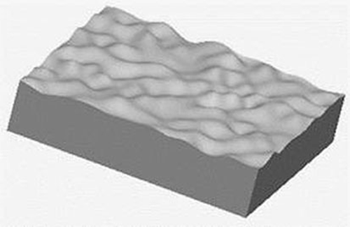
Numerical simulation is one of the most important methods in tribology research, which simplifies research works to some extent. To simulate the frictional thermo-mechanical coupling problem of real rough surfaces, a numerical model of rough surface must be established first, since this kind of representation is an important precondition for the reliability of simulation. As many engineering surfaces possess fractal characteristics, the rough surface used in this paper is generated based on the two-variable Weierstrass–Mandelbrot (W–M) function (Yan and Komvopoulos Citation1998; Prasanta and Niloy Citation2007). Figure shows the solid model with a fractal rough surface.
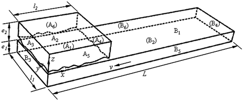
In order to simply the numerical work, the analysis model between rough surfaces is presented for a smooth flat solid named B against a rough solid named A of which the surface is characterized by W-M function mentioned above. The model is as Figure .
In Figure , A1, B1 represent the friction surfaces of solid A and B, respectively, and A2, B2 are the back surface of the friction surface of solid A and B, respectively, A3, A4, A5, A6, B3, B4, B5, B6 are the side surfaces of solid A and B, respectively, e1, e2 are the thickness of solid A and B, respectively, l, L are the length of solid A and B, respectively.
2.2. Thermal conduction model
To apply the thermal model, it is assumed that
| (1) | The coefficient of friction remains constant during sliding, and the frictional force accords with Coulomb law. | ||||
| (2) | The amount of heat generation by wear is very small relative to the heat generated by friction, we neglect the effect of material wear, and assume kinetic energy all translate into frictional heat which is absorbed by frictional pair. Thus, the frictional heat flux q(x,y,t) can be figured out as | ||||
(1)
where, p(x,y,t) is the interface contact pressure of frictional surface which can be obtained by solving the thermo-mechanical coupling problem; μ is the coefficient of friction; v(x,y,t) is the relative sliding velocity between solid A and B.
| (3) | To solve the assignment of the frictional heat flux between contact surfaces, the frictional heat flux coupling is considered. It is assumed that in the local contact point the local instantaneous temperatures of solid A (TA) and solid B (TB) are equal and the local contact interfaces are a series of very small ideal planes. So the partition of frictional heat flux q on the local contact point between solid A and B is assigned naturally according to their thermo-physical properties of material. This coupling condition on the local contact point can be written as: | ||||
(2)
where qA is the heat flux entering into solid A from the local contact point and qB is the heat flux entering into solid B from the local contact point.
The thermal conduction equation of solid A and B under the Cartesian coordinate system can be expressed as:(3)
where ρ, c, k, and T are density, specific heat, thermal conductivity and temperature of material, respectively. The subscripts of A and B denote solid A and B, respectively. t is the sliding time.
The surfaces A1 of solid A is partially in contact with the surface B1 of solid B. So the thermal boundary conditions of the two surfaces (A1 and B1) are as follows: in the local contact zone there is frictional heat flux generation and thermal conductivity of solid A and B. But outside the local contact zone, the surface is subjected to the thermal radiation and forced convection condition. Thus, the boundary conditions on the working surfaces (A1 and B1) can be expressed as:
(4)
where
and where Tf is the environmental temperature, hi1 is the convection coefficient, qi is the heat flux entering into solid A or solid B from the local contact zones and can be obtained from the heat flux coupling condition, σ is the Stefan–Boltzman constant, A′ is the area of non-contact zones of the working surface of solid A or solid B. Kc is the thermal conduction coefficient of the local contact interface between solid A and B. The subscripts of A and B denote solid A and solid B, respectively.
According to the assumption (3), Equation (4) can be rewritten as(5)
In the above Equation (5), the contact surface is rough and the heat source is moving, so the frictional thermal flow on the real micro-contact interface is coupled. This is expressed as the contact function g(m). When g(m) is equal to 1, it indicates that there exists heat flux entering into solid A and solid B at the real contact spots (micro-contact zones).When g(m) is zero, it indicates that there exists thermal convection and thermal radiation in the micro-separation zones.
Because we only study the temperature field on micro-contact region and the sliding time is very short, the top surface (A2) of solid A and the bottom surface (B2) of solid B are assumed to be adiabatic. All the side surfaces, namely A3, A4, A5, A6 of solid A and B3, B4, B5, B6 of solid B are assumed to be adiabatic too. This is written as:(6)
where ni (i = x,y,z) is the normal direction of the boundary surface of solid A or solid B.
Thermal initial condition is as follows.(7)
2.3. Elasto-plastic contact problem
It supposes the materials of contact solid bodies are homogeneous and their thermal properties are invariant with temperature, and the elasto-plastic materials obey the von Mises yield criterion.
An incremental setting may be established that obtains a solution for a time tn+1 given the state at time tn. Using rectangular coordinates coincident with the principal axes, the stress–strain relations for an isotropic body are written in an incremental form Wang and Shao (Citation1988)(8)
where(9)
and where is incremental stress matrix,
is the total incremental strain matrix,
is the material elastic matrix and
the material plastic matrix.
is a matrix of thermal strain increment. Supposed the thermal expansion only produces normal strain. For the 3-D case, the thermal strain vector is:
(10)
in which α is a thermal expansion coefficient of the material which is assumed as a constant.
In the above Equation (8), the elasto-plastic material may be elastic deformation, plastic deformation or elasto-plastic deformation under the applied external load. When [D]ep is equal to[D]e, it indicates that there exists elastic deformation. When [D]ep is equal to[D]p, it indicates that there exists plastic deformation. When [D]ep is equal to ([D]e−[D]p), it indicates that there exists elasto-plastic deformation.
2.4. The structural boundary conditions
The structural boundary conditions are investigated as follows. Assume that solid A is immobile and solid B moves along −x direction. As in Figure , the applied pressure Pz exerts uniformly on the back surface (A2) of solid A along z direction and the stress distribution is expressed as σz. The displacements of two side surfaces (A3 and A4) of solid A along x direction are equal to zero and the displacements of other two side surfaces (A5 and A6) of solid A along y direction are equal to zero. So the structural boundary conditions of solid A can then be described as(11)
To simulate the motion of solid B, the whole solid B is applied certain displacement Sx along x direction. And the displacement of solid B along y direction is equal to zero. The displacement of the surface B2 of solid B is immobile along z direction. Thus, the boundary condition of structure can be expressed as:(12)
2.5. The coupling between temperature and stress
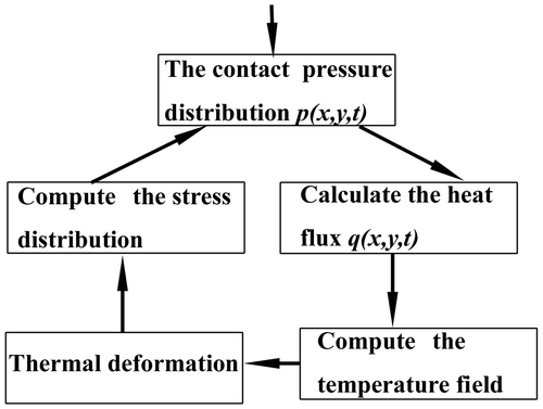
The coupling between the temperature field and the stress field is completed via frictional heat flux. From the contact pressure between solid A and solid B, it leads to the frictional heat flux described by a relative sliding velocity and the contact pressure with a dynamic frictional coefficient. With the varying heat flux entering into the sliding bodies, the temperature of the sliding bodies changes and leads to thermal deformation. The resulting thermal deformation changes the stress distribution and the subsequent contact pressure distribution. The resulting varying contact pressure further affects the frictional heat flux.
The above coupling mechanism is illustrated in Figure . In the figure, the friction heat flux q(x,y,t) is the bridge of the thermal/structure coupling. It can be expressed in Equation (1). Then the variation of the contact area during the process of loading and the frictional sliding is developed by writing a subroutine and using the nonlinear finite element multiphysical methods in ABAQUS software.
3. Result and discussion
3.1. Parameters
For all the models used in this paper, the materials of rough solid A and flat B are AST1045 and AST5140, respectively. The material mechanical and thermal properties and simulation parameters are summarized in Table (Editorial of Databook Committee of Materials for Mechanical Engineering Citation1994; Practical Book of Engineering Materials Editorial Board Citation1989).
Table 1. Parameters and material properties of solid A and solid B in simulations.
According to its definition, the equivalent elastic modulus Ee can be described as:(13)
where λ1 and λ2 are Possion’s ratio of solid A and B, respectively. E1 and E2 are the elastic modulus of solid A and B, respectively.
From Equaion (13), the equivalent elastic modulus of E-R model or P-R model are 213.33 GPa, and that of P-E model or P-P model is equal to 110.34 GPa. And the frictional coefficient is equal to 0.15. The sliding distance (L) is equal to 1800 , the relative sliding velocity is 30 m/s. The dimensionless load (Pz/Ee), which is the ratio of the uniform pressure Pz to the corresponding equivalent elastic modulus Ee, is assigned to be the same in all analysis models.
3.2. Loading
Figure gives the variation of dimensionless contact area (also named contact area ratio, which is equal to the ratio of the real contact area Ar to the nominal contact area A0) vs. the dimensionless load (Pz/Ee) from different analysis models, including E-R model, P-R model, P-E model and P-P model. In this figure, the curve marked E-R means the contact model between an elastic rough solid and a rigid flat one, P-R and others are similar.
Figure 4. Variation of the contact area ratio vs. the dimensionless load using different analysis models (here, P-R means P-R model between an elasto-plastic rough solid and a rigid flat one and so on).
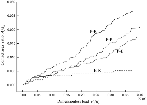
From Figure , one can see that the real contact area obtained from different models is only a little portion of the nominal contact area during the whole uniform loading process. For example, when the loading process is finished, the real contact area of E-R model (only purely elastic deformation) is still less than 5%. As the external applied load increases, more and more contact asperities come into plastic deformation, and then the real contact areas from other elasto-plastic models (such as P-R, P-E, and P-P model) increase. Of course, since the scale of the simulation is micron, the real contact area of the result is a little bigger than that of the asperities contact in much smaller scale. But the whole varying trend of the contact area ratio with the dimensionless load is similar to the results of the experiments in Ji, Chen and Yao (Citation1992). The results of E-R model and P-R model are consistent with those by Pei et al. (Citation2005) in 2005.
The contact area ratios of P-E model and P-P model are the same before the beginning of plastic deformation of solid B. It means that the real contact areas from P-E model and P-P model are similar under small load. As the external load increases, the plastic deformation of solid B in P-P model arises, but there is still purely elastic deformation of solid B in P-E model. These make the real contact areas of these two models different. Compared with several elasto-plastic contact models, the real contact area from P-R model is the biggest under the same dimensionless load because solid B of this model is assumed to be a rigid body.
3.3. Frictional sliding
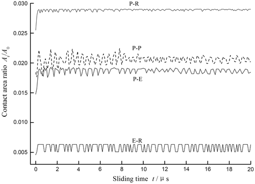
Under the same dimensionless load (Pz/Ee = 0.00035), the contact area ratio (Ar /A0) vs. sliding time from different analysis models is presented in Figure . One can see that the real contact area increases quickly in the initial stage of sliding and then varies in a small range with the increase in sliding time, which may be attributed to the transient temperature rise of the frictional interface.
Figure shows the curves of the maximum contact temperature vs. sliding time for different analysis models, where the results are obtained under the same dimensionless load (Pz/Ee = 0.00035). It can be seen that the instantaneous contact temperature of frictional surface rises rapidly in a short time (t = 1.3 μs) because of the delay of heat conduction and the great frictional heat flux inputting into the local contact regions. When the rough solid contacts with the flat one under the normal load, only a few asperities come into contact and the contact pressure on the micro-contact zones is very large. At the moment of frictional sliding, the relative sliding velocity (v) changes suddenly (0→30 m/s). According to the Equation (1), all these cause a great amount of frictional heat flux on the micro-contact zones and increase the instantaneous contact temperature. With the increase in the sliding time, the transient contact temperature rising speed decreases gradually due to the constant sliding velocity, the heat conduction of the material itself, the heat conduction between contact bodies and the convection heat transfer. And the real contact area almost keeps constant during the constant frictional sliding process. During this frictional sliding process, the maximum contact temperature from the purely elastic model (E-R model) is higher than that from the other elasto-plastic models, the real contact area is contrary, which may be attributed to thermal expansion that intensifies the non-conformity of contact geometry, on the other hand, plastic deformation makes the contact more conformal. Chen and Wang (Citation2008) also pointed out that thermal expansion would intensify the non-conformity of contact geometry and might shrink the contact area under the purely elastic model.
Figure 6. Maximum surface contact temperature vs. sliding time for different solid body contact deformation.
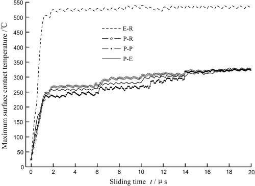
From Figure , we can see that the contact area ratios of E-R model, P-R model, P-E model and P-P model increases noticeably in the initial stage of frictional sliding. When the sliding time is zero (t = 0), the contact area ratios from E-R model, P-R model, P-E model and P-P model are about 0.005, 0.025, 0.015 and 0.018, respectively. When the frictional sliding begins (t = 0.1 μs), under the action of friction force, the contact area ratios corresponding to different analysis models attain about 0.0055, 0.028, 0.016 and 0.019, respectively. Compared with other elasto-plastic models (P-R model, P-E model and P-P model), when the sliding time changes from 0 to 0.1 μs, the contact area ratios corresponding to various elasto-plastic models increase by about 7.7, 6.7 and 5.6%, respectively. Obviously, although the rough solid A has the same elasto-plastic deformation property, the ratio of the contact area from P-P model in which the contact solid B has also elasto-plastic deformation property increases at the slowest at the moment of frictional sliding. When the high temperature (‘hot spotting’) comes forth (t = 1.3 μs), compared with the contact area ratio at the moment of sliding, the contact area ratios corresponding to various elasto-plastic models increase by about 16, 17 and 17%, respectively. This is because the difference of hot spotting temperature from different elasto-plastic models is small (see Figure ).
4. Conclusions
The variations of the real contact areas obtained from various analysis models have been performed. These analysis models included a contact model between an elastic rough solid and a rigid flat one, an elasto-plastic rough solid and a rigid flat one, an elasto-plastic rough solid and an elastic flat one, an elasto-plastic rough solid and an elasto-plastic flat one. And the thermo-mechanical coupling and the frictional heat flux coupling between the working surfaces of a rough solid and a flat one were investigated.
The analysis and simulation identified that the real contact area from various analysis models was only a small fraction of the nominal contact area during the process of loading and frictional sliding, but the value was different.
| (1) | The real contact area was not only related to the normal load and the shape of surface rough, but also related to solid body contact deformation during loading process. The contact area ratio from the E-R contact model between an elastic rough solid and a rigid flat one was less than 5‰, and was the smallest than that from other elasto-plastic analysis models. With the increase in the applied normal load, more and more contact asperities came into plastic deformation, and the real contact area from the elasto-plastic model increased. Under the same dimensionless load, the contact area ratio from the P-R contact model between a elasto-plastic rough solid and a rigid flat one was the largest than that from other analysis models, but it was still less than 3%. | ||||
| (2) | Under the comprehensive influences of frictional force and heat, the real contact area increased noticeably at the moment of the abrupt change of the sliding velocity and of the hot spotting coming into being, no matter what kind of the solid body contact deformation is. And then the real contact area varied in a small range during the constant sliding process. For the case with elasto-plastic deformation, the contact area ratio from the P-P contact model between an elasto-plastic rough solid and an elasto-plastic flat one increased the slowest at the moment of sliding. But when the hot spotting came into being, the ratio of the contact area from various elasto-plastic contact models increased almost the same. | ||||
Notes on contributors
Jianmeng Huang, born in 1973, received the PhD degree from Fuzhou University, China, in 2010. She is currently an associate professor at School of Mechanical Engineering and Automation, Fuzhou University, China. Her Scientific interests include methods of analytical and computer modelling in dry friction, tribological properties of components, etc.
Chenhui Gao, born in 1953, is currently a professor at School of Mechanical Engineering and Automation, Fuzhou University, China. He received the PhD degree from Mechanical Research Institute of China, in 1990. His research interests include methodological, theoretical and experimental fundamentals of friction and wear. He has published more than 150 works including one book.
Chao Zhou, born in 1978, is currently an associate professor at School of Mechanical Engineering and Automation, Fuzhou University, China. He received his PhD degree from Fuzhou University, China, in 2012. His research interests include synthesis of component surfaces, tribological properties of components, etc.
XieZhao Lin, received the MS degree in mechanics from Fuzhou University, FuJian, CHINA, in 2001 and the PhD degree in mechanical engineering from the ZheJiang University, CHINA, in 2010. He is currently an associate professor at School of Mechanical Engineering and Automation, Fuzhou University, China. His current principal research activities are the development of computer-aided design systems for design and simulation of microelectromechanical devices, mechanical structures and the tribological properties of micro-components.
Funding
This research is supported by the National Natural Science Foundation of China (NSFC) [grant number 51205062], [grant number51175085]; the Natural Science Foundation of FuJian under [grant number 2011J01299]; the Education Council of FuJian Province China under [grant number JA11029].
Disclosure statement
No potential conflict of interest was reported by the authors.
References
- Carbone, G., and F. Bottiglione. 2008. “Asperity Contact Theories: Do they Predict Linearity between Contact Area and Load?” Journal of the Mechanics and Physics of Solids 56: 2555–2572.10.1016/j.jmps.2008.03.011
- Caroline, B., N. Daniel, and M. C. Baietto. 2012. “Contact Analyses for Anisotropic Half Space: Effect of the Anisotropy on the Pressure Distribution and Contact Area.” Journal of Tribology 134: 031401.
- Chen, W. W., and Q. J. Wang. 2008. “Thermomechanical Analysis of Elastoplastic Bodies in a Sliding Spherical Contact and the Effects of Sliding Speed, Heat Partition, and Thermal Softening.” Journal of Tribology 130: 041402.10.1115/1.2959110
- Chung, J. C. 2010. “Elastic–plastic Contact Analysis of an Ellipsoid and a Rigid flat.” Tribology International 43: 491–502.10.1016/j.triboint.2009.08.005
- Editorial of Databook Committee of Materials for Mechanical Engineering. 1994. Databook of Material Property for Mechanical Engineering. 1st ed. Beijing: China Machine Press.
- Hasan, S., and O. Alaettin. 2008. “Thermomechanical Analysis of Elastoplastic Medium in Sliding Contact with Fractal Surface.” Tribology International 41: 783–796.
- Jamil, A., and F. Kambiz. 2005. “Elastic-plastic Contact Model for Rough Surfaces Based on Plastic Asperity Concept.” International Journal of Non-linear Mechanics 40: 495–506.
- Jeng, Y. R., and P. Y. Wang. 2003. “An Elliptical Microcontact Model Considering Elastic, Elastoplastic, and Plastic Deformation.” Journal of Tribology 125: 232–240.10.1115/1.1537744
- Ji, G. B., G. Z. Chen, and M. L. Yao. 1992. The Principle of Friction and Wear. 1st ed. Beijing: China Coal Industry Publishing House.
- Kogut, L., and I. Etsion. 2002. “Elastic-Plastic Contact Analysis of a Sphere and a Rigid Flat.” Journal of Applied Mechanics 69: 657–662.10.1115/1.1490373
- Li, L., I. Etsion, and F. E. Talke. 2010. “Contact Area and Static Friction of Rough Surfaces with High Plasticity Index.” Journal of Tribology 132: 031401.10.1115/1.4001555
- Lin, L. P., and J. F. Lin. 2006. “A New Method for Elastic-plastic Contact Analysis of a Deformable Sphere and a Rigid Flat.” Journal of Tribology 128: 221–229.10.1115/1.2164469
- Liu, S. B., and Q. Wang. 2001. “A Three-dimensional Thermomechanical Model of Contact between Non-conforming Rough Surfaces.” Journal of Tribology 123: 17–26.10.1115/1.1327585
- Liu, G., Q. Wang, and S. B. Liu. 2001. “A Three-dimensional Thermal-mechanical Asperity Contact Model for Two Nominally Flat Surfaces in Contact.” Journal of Tribology 123: 595–602.10.1115/1.1308044
- Liu, G., Q. Wang, and Y. Ao. 2002. “Convenient Formulas for Modeling Three-dimensional Thermo-mechanical Asperity Contacts.” Tribology International 35 (7): 411–423.10.1016/S0301-679X(02)00022-1
- Ovcharenko, A., G. Halperin, G. Varberne, and I. Etsion. 2007. “In Situ Investigation of the Contact Area in Elastic-plastic Spherical Contact during Loading-unloading.” Tribology Letters 25: 153–160.10.1007/s11249-006-9164-y
- Ovcharenko, A., G. Halperin, and I. Etsion. 2008a. “Experimental Study of Adhesive Static Friction in a Spherical Elastic-plastic Contact.” Journal of Tribology 130: 021401.10.1115/1.2842247
- Ovcharenko, A., G. Halperin, and I. Etsion. 2008b. “In situ and Real Time Optical Investigation of Junction Growth in Spherical Elastic-plastic Contact.” Wear 264: 1043–1050.10.1016/j.wear.2007.08.009
- Pei, L., S. Hyun, J. F. Molinari, and M. O. Robbins. 2005. “Finite Element Modeling of Elasto-plastic Contact between Rough Surfaces.” Journal of the Mechanics and Physics of Solids 53: 2385–2409.10.1016/j.jmps.2005.06.008
- Practical Book of Engineering Materials Editorial Board. 1989. Practical Book of Engineering Materials. 1st ed. Beijing: Standards Press of China.
- Prasanta, S., and G. Niloy. 2007. “Finite Element Contact Analysis of Fractal Surfaces.” Journal of Physics D: Applied Physics 40: 4245–4252.
- Pugliese, G., S. M. O. Tavares, E. Ciulli, and L. A. Ferreira. 2008. “Rough Contacts between Actual Engineering Surfaces.” Wear 264: 1116–1128.10.1016/j.wear.2007.08.027
- Putignano, C., L. Afferrante, G. Carbone, and G. Demelio. 2012. “The Influence of the Statistical Properties of Self-affine Surfaces in Elastic Contacts: A Numerical Investigation.” Journal of the Mechanics and Physics of Solids 60: 973–982.10.1016/j.jmps.2012.01.006
- Robert, L. J., and G. Itahak. 2006. “A Statistical Model of Elasto-plastic Asperity Contact between Rough Surfaces.” Tribology International 39: 906–914.
- Wang, X. C., and M. Shao. 1988. The Principle and Numerical Method of Finite Element Method. 1st ed. Beijing: Tsinghua University Press.
- Yan, W., and K. Komvopoulos. 1998. “Contact Analysis of Elastic-plastic Fractal Surfaces.” Journal of Applied Physics 84 (7): 3617–3624.10.1063/1.368536

