Abstract
Heat transfer analysis of a packed bed-phase change material (PCM) latent heat thermal energy storage system is presented in this article. The spherical capsules, containing water with a nucleation agent as a PCM, fill the thermal storage tank used for an air-conditioning commercial application. The heat transfer fluid that circulates through the tank and around the capsules is an aqueous solution of ethanol. In this study, the experimental model is tested to use for analysing the thermal performance of packed bed-PCM latent. The governing equations are based on energy balance in the spherical capsules where the results are compared numerically using simple, explicit and finite difference technique. The results obtained are used only for charging process. The effects of mass flow rate and inlet heat transfer fluid temperature are investigated on the time duration for solidification. The contribution of this article is using ethanol as transfer fluid in thermal storage system.
1. Introduction
The use of thermo-accumulation has as main objective the reduction of energy demand during the hours of the use of HVAC system. Therefore, the chillers have smaller capacity and work during the night, producing chilled water, which will be accumulated in appropriate tanks. During the day, cold water accumulated in the tank provides chilled water required for a given case, with the remainder being supplied by refrigeration units. With this, the capacity of the coolers can be reduced, providing a lower electricity demand.
Another advantage of the system is to allow the shutdown of the chillers at peak times, from 18:00 to 21:00 h in Brazil, leaving only the circulation pumps of cold water connected. Cold water during this time is provided by thermal accumulation tank. In case of ice storage, being more compact is most common on smaller commercial buildings or where space for the storage is limited. Ice storage systems, while requiring more refrigeration, can produce chilled water at lower temperature, enabling the use of smaller chilled water pumps, piping and coils. According to Bhatia (Citation2010), the encapsulated ice systems consist of water contained in plastic containers surrounded by coolant, all contained within a tank or in other storage vessels. During the charging cycle, subfreezing coolant from a chiller is circulated through the storage tank and past the plastic containers, freezing the ice. Discharge is accomplished by circulating warm coolant through the tank and past the containers, melting the ice. The coolant may be routed directly to the load or isolated from the load via a heat exchanger. The most common form of plastic container is a dimpled ball about 4 inches in diameter. The spherical shape creates a relatively high heat transfer area per unit of water being frozen, while the dimples allow for expansion and contraction while cycling between liquid and solid states. Kousksou et al. (Citation2005) presented dynamic modelling of the thermal storage of an encapsulated tank. The performance of the cold storage air-conditioning systems depends basically on coolant flow rate inlet temperature and the position of the tank, as well as the supercooling phenomena. The study on ice formation inside a spherical capsule was investigated by Ismail et al. (Citation2003) where the time for complete solidification increases with the increase in the external fluid temperature. Also, the thermal conductivity of the capsule material has a strong effect on the time for complete solidification and the solidified mass fraction. In the review by Abdel-Rehim (Citation2011), the author presents a heat transfer analysis of a packed bed-phase change material (PCM) capsules latent heat thermal energy storage system. The conclusion presented by the author is that the charging and discharging rates are significantly higher for the capsule of a smaller radius compared to those of a larger radius. Also the complete solidification time is longer compared to the melting time.
The use spherical capsules to encapsulate the PCM in air-conditioning applications has been analysed by Fang and Shuangmao (Citation2010). Studied experimentally, the operation characteristics of cold storage air-conditioning systems with spherical capsules packed bed. The spherical capsules with outside diameter of 100 mm and wall thickness of 1 mm were filled with water. The experimental results indicated that the cold storage air-conditioning systems with spherical capsules had a better performance and could work during the charging and discharging periods. Arnold (Citation1990) analysed the heat transfer during the freezing and melting process by performing a series of charging and discharging experiments.
Elghnam et al. (Citation2012) presented the results of an experimental study on the heat transfer during freezing (charging) and melting (discharging) of water inside a spherical capsule of the type often found in the beds of thermal (ice) storage systems used for building air-conditioning systems with spherical capsules of different diameters, and materials are tested. Bedecarrats et al. (Citation2009) demonstrated an experimental investigation of the performance of an encapsulated phase change energy storage during the charging and the discharging processes. The spherical capsules, containing water with a nucleation agent as a PCM, fill the thermal storage tank.
Assis et al. (Citation2007, Citation2009) conducted experimental and numerical studies on melting process in a spherical shell. They provided a correlation for the melting fraction versus an appropriate combination of the Grashof, Stefan and Fourier numbers. Also, they performed another combined experimental and numerical study on the solidification of PCM inside a spherical shell with various diameters.
Medrano et al. (Citation2009) experimentally studied heat transfer characterization of five small heat exchangers working as latent heat thermal storage systems during the charge and discharging processes. The results indicated that the double pipe heat exchanger with the PCM embedded in a graphite matrix had the highest values. Erek and Ezan (Citation2007) performed numerical and experimental studies for assessing the effects of thermal parameters on the storage performance of an ice-on-coil energy storage system.
Mueller (Citation2005) has developed a numerical model which allows reasonable predictions of bed porosity when looking at large cylinders packed with spherical capsules. Eames and Adref (Citation2002) studied experimentally the characteristics of heat transfer for water contained in spherical elements in both charging and discharging processes and described a novel method to measure interface position during solidification.
Therefore, this research is important for the scientific community, that is it shows the experimental and numerical results based on studies of a packed bed-PCM latent heat thermal energy storage system. At last, by means of numerical results, one can predict the loading time ice tanks containing spherical capsules.
2. Experimental investigation
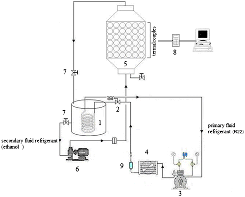
A schematic diagram of the experimental set-up is shown in Figure .
Figure 1. Schematic diagram of experimental set-up. (1) Coil pipes evaporator, (2) expansion valve, (3) compressor, (4) condenser, (5) thermal storage tank, (6) circulating pump, (7) flow control valve, (8) data logger and (9) filter drier.
The thermal storage tank is made of steel of 300 mm internal diameter, 1.5 m in length and 10 mm thick, insulated by a 50-mm-thick layer expanded polyurethane. The storage tank contains 200 spherical capsules of 76 mm diameter, 2 mm thickness and arrayed internally by such that the porosity of the tank filling is 0.42 where porosity or void fraction is a measure of the void “empty” spaces in a material, and is a fraction of the volume of voids over the total volume, between 0 and 1, or as a percentage between 0 and 100% and depends on the number of spheres and the diameter of the tank. In practice, the maximum porosity for an ice ball storage system is about 52–60%.
The refrigeration unit is a simple vapour-compression cycle, operated with R22. It includes a compressor (7hp), condenser (forced type), filter drier, thermostatic expansion valve and coil pipes evaporator. Three spheres are placed at the bottom near the entry of the working fluid at mid height of the tank and at the top of the tank near exit. Each sphere is fitted with T-type thermocouples localized at the centre of the sphere. Nine thermocouples are distributed along the length of the storage tank to measure the temperature distribution along tank axis. Additional thermocouples are installed at entry and exit of the working fluid. All those thermocouples are calibrated with precision of ±0.5 °C and are connected to data acquisition system which delivers the signals to a dedicate PC.
The primary refrigerant (R22) from the refrigeration machine is allowed to circulate through the coil pipes of the secondary fluid circuit submersed into the tank filled with ethanol, where it is cooled until it reaches the required temperature. When the ethanol reaches the prescribed temperature, the entry to the storage tank is opened to receive the cooled ethanol circulated by pump. This process is continued until the thermocouples in the three reference spheres indicate the same temperature without any change with time. The ethanol is then forced to circulate into the storage tank from the bottom to the top by a dedicated pump. The flow is controlled by a control valve and measured by a calibrated orifice plate connected to a pressure transducer. The temperature of the secondary fluid (ethanol) is measured by a calibrated T-type thermocouple. The secondary fluid is permitted to circulate until the temperature along the storage tank axis reaches the pre-established value, then the storage tank is considered charged and the ethanol flow is shut down. The experimental conditions are presented in Table , while Table shows a summary of estimated uncertainties of the measured quantities. All experimental conditions are defined by the author themselves, in other words, the maximum flow rate of pump corresponds to 3.30 kg/s. Besides that, the cooling machine can reduce the temperature of the secondary fluid until −20 °C.
Table 1. Experimental conditions.
Table 2. Summary of estimated uncertainties.
3. Numerical analysis and governing equations
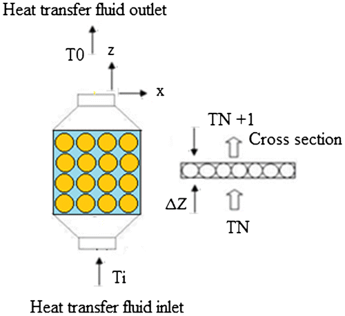
Consider the tank as the control volume as shown in Figure .
Figure shows the layout of the physical system that has been investigated. Assumptions involved in this study are as follows
| (1) | Variation of temperature is only along the axial direction, i.e. the temperature is independent of radial position. | ||||
| (2) | The flow in the tank is axial and incompressible. | ||||
| (3) | The thermophysical properties of the heat transfer fluid are invariant with temperature. | ||||
| (4) | The porosity of the bed, which is defined as the ratio of the void volume to the total volume of the packed bed, is 0.42. | ||||
| (5) | Radiant heat transfer between the capsules is negligible. | ||||
| (6) | There is no internal heat generation in the bed. | ||||
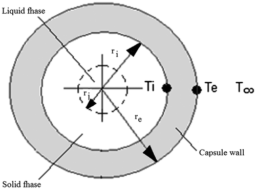
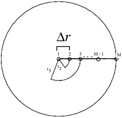
The model study of spherical capsules can be seen in Figures and .
The one-dimensional heat conduction equation for spherical geometry used in the radial direction in the solid and liquid regions can be written as:(1)
The packed bed column is divided into N elements, each containing PCM capsules surrounded by heat transfer fluid. TN and TN+1 are the inlet and outlet temperatures of the thermal energy system; the energy balance on a layer leads to:(2)
where n is the number of spheres in the layer, is the heat exchanged between each spherical capsule and the working fluid. Equation (2) can be written in finite difference as:
(3)
where represents the fluid temperature of the layer, while i and i + 1 represent two successive time intervals. Moreover, if we assume that temperature at the centre of the layer, Tm is the average value between entry and exit temperatures of the layer TN and TN+1 respectively, then Equation (3) can be written in the form:
(4)
Equation (4) can be written for each layer forming a system of N simultaneous equations. The temperature at entry to the first layer TN=1 is known from the boundary condition of the problem and is considered constant.
Using approximations forward to the first derivations (temporal and spatial) and the nearest three points for the second space and substituting these in Equation (1) derived, we arrive at an approximation by finite differences for the equation of heat conduction of the spherical capsule for the internal nodes as shown in Equations (Equation5(5) ) and (Equation6
(6) ).
(5)
With rearranging Equation (Equation5(5) )
(6)
The equation of energy balance in the radial direction to the central node is:(7)
The discretized form is:(8)
which after some algebraic manipulations can be rewritten in the form:(9)
The equation for node M in the Figure may be obtained from the equation valid for the internal points of the domain. Writing the Equation (Equation6(6) ) for m = M can be rewritten as:
(10)
The temperature at the border M + 1 is obtained by applying the boundary condition on the surface right with convection.(11)
The discretized form is:(12)
which after some algebraic manipulations can be rewritten in the form:(13)
Substituting the Equation (Equation13(13) ) into the Equation (Equation10
(10) ) can be rewritten as:
(14)
The numerical solution of the problem of energy storage in systems composed of tank full of spherical capsules filled with PCM is realized using a marching technique, in which the phase-changing problem inside the spherical capsule is coupled with the energy balance equation between the spherical boundary and the working fluid.
The system of equations shown below is obtained where α = αliq or α = αsol depending on the condition of the PCM.
4. Results and discussions
Numerical simulations were realized in order to investigate the effect of the working fluid entry temperature and the mass flow rate. The working fluid entry temperature was varied between −5, −10 and −12 °C.
4.1. Effect of inlet working fluid temperature during charging process
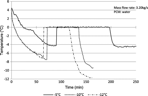
Figure shows the experimental data and represents the variation of the temperature at the centre of the last sphere layer with time during the charging process under conditions of the secondary coolant mass flow rate of 3.20 kg/s and inlet temperature (Tin) ranging from −5 to −12 °C. The initial temperature of sphere corresponds to the temperature of maximum density of water.
It is also shown that the lower the temperature of the working fluid inlet, the lower the time of the complete solidification of PCM. It is also evident that at the end of the process, the temperature nears to the initial temperature of the working fluid. It can also be seen that the lower inlet coolant temperature can reduce the subcooling of water and the total charging time. In practical situations, a low coolant temperature to promote nucleation is often required in order to establish reasonable heat exchange rates during periods of charging and discharging.
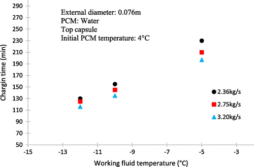
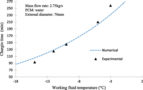
The effect of the entry temperature of the working fluid is shown in Figure . It can be seen that the decrease in the working fluid temperature from −5 to −12 °C reduces greatly the dimensionless time for complete charging in the same way that for higher mass flow rates.
The reason is that for lower temperatures, the working fluid is greater ∆T, thereby increasing the rate of heat transfer between the fluid and spherical capsules.
4.2. Effect of mass flow rate during charging process
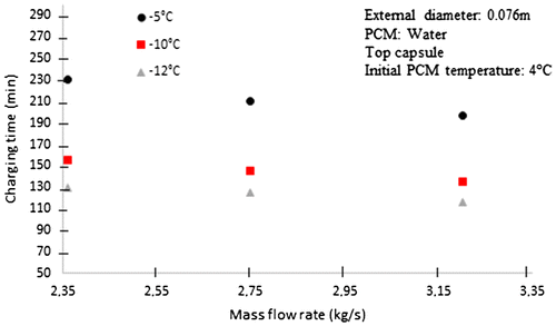
The effect of mass flow rate can be seen in Figure , where for higher magnitudes of mass flow rate is lower the charging time of the storage tank. The reason is that for high mass flow rate, the coefficient of heat transfer by convection is higher; in this way, the heat transfer between the working fluid and the spherical capsules is increasing.
4.3. Storage tank freeze rate
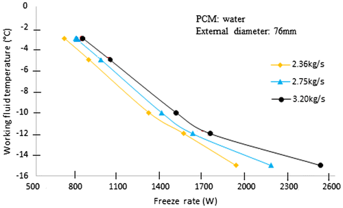
Figure depicts the freeze rate of an sample ice storage tank. When the entering fluid temperature is −5 °C and the fluid flow rate is 2.36 kg/s, the freeze rate of this tank is 870 W. By reducing the entering fluid temperature to −10 °C, with the same fluid flow rate, the freeze rate increases to about 1290 W. However, to achieve the equivalent, higher freeze rate with the original entering fluid temperature of −5 °C would require nearly 45% high the fluid flow rate.
5. Comparison of the experimental and numerical results
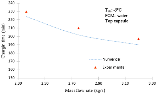
The effect of varying the mass flow rate of the working fluid on the time for complete solidification of the storage tank for 2.36–3.20 kg/s with inlet temperature of −5 °C is shown in Figure together with the experimental results.
Figures and show comparative results of the numerical predictions from the numerical model of the solidification process inside a spherical capsule and experimental tests realized to validate the model. It can be seen that at the duration time of the changing process, the computational charging time is similar to the experimental results.
However, the numerical values are lower than the experimental results at the high inlet temperature of the process. We see the results of the calculation giving the temperature versus time in the same points as in the experimental study and in the same conditions. It is apparent in these figures that the agreement between the shapes of the experimental and theoretical curves is correct but not really perfect. It can be assumed that the experimental results are affected by the thermal contribution of the ambient air (the insulation of the tank is not really perfect).
However, in these comparisons, there is little difference between calculated and experimental values. Therefore, this model can be used to predict the dynamic characteristics of the cool storage system. Comparisons of the numerical predictions with the experimental measurements show a relatively good agreement confirming the validity of the model.
The advantage of the model is that it permits the calculation of the total stored latent energy and the total loading time for solidification.
6. Conclusions
A model for simulation of the process of heat transfer of a latent heat storage system of packed bed of spherical capsules filled with PCM was developed and solved numerically using a finite difference approach and moving grid technique. The numerical grid was optimized and the predicted results were compared with experimental results to establish the validity of the model. The working fluid entry temperature, the mass flow as well as the capsule temperature were investigated.
The higher the inlet heat transfer fluid temperature, the higher the time for complete charging. Similarly, the higher the mass flow rate of the heat transfer fluid, the shorter the time for complete charging.
Increasing the flow rate of the heat transfer fluid increases the pump energy use. Lowering the temperature entering the tank increases the chiller energy use. Well-designed ice storage systems balance these two competing concerns.
The simplified model considering the spherical capsules as exchangers has confirmed the experimental results and is useful for further investigations to size and optimize the process.
In commercial conditions, the charge mode must be realized in a given time. These results show the influence of the mass flow rate and the inlet temperature on the duration of the process. The duration of the charge mode is decreased when the final inlet temperature is lowered and when the mass flow rate is increased. So, to make a completed charge mode in a given duration, we can choose the appropriate couple flow rate and inlet temperature.
| Nomenclature | ||
| V | = | volume of storage tank, m3 |
| A | = | cross-sectional area of the storage tank, m2 |
| cp | = | Specific heat, J/kg °C |
| h | = | convective heat transfer coefficient, W/m2 K |
| l | = | length of the tank, m |
| L | = | latent heat of solidification, J/kg |
| = | mass flow rate, kg/s | |
| PCM | = | phase change material |
| = | heat exchanged, W | |
| Q | = | total energy stored, W |
| r | = | shell radius, m |
| T | = | temperature, °C |
| T∞ | = | ambient temperature, °C |
| k | = | thermal conductivity of PCM, W/mK |
| N | = | number of elements in the bed |
| re | = | external shell radius, m |
| ri | = | internal shell radius, m |
| rj | = | interface position, m |
| Δ | = | increment |
| T | = | time, s |
| Rtotal | = | total thermal resistance, m2 K/W |
| Greek symbols | ||
| α | = | thermal diffusivity, m2/s |
| ρ | = | density, kg/m3 |
| ∆ | = | increment |
| Subscripts | ||
| F | = | working fluid |
| l | = | liquid phase |
| s | = | solid phase |
Notes on contributor
André Panesi is professor of engineering and technology in Federal Institute of São Paulo, working with thermodynamics, refrigeration and air conditioning. He has 25 years of teaching experience in technical and higher education. For the moment, he undertakes research work on energy recovery, such as photovoltaics energy and mechanical automation.
Disclosure statement
No potential conflict of interest was reported by the author.
References
- Abdel-Rehim, Z. S. 2011. “Heat Transfer Analysis of a Packed Bed-PCM Capsules Latent Heat Thermal Energy Storage System.” Energy Sources, Part A 33 (14): 1326–1343.10.1080/15567030903330868
- Arnold, D. 1990. “Dynamic Simulation of Encapsulated Ice Stores-Part I: The Model.” ASHRAE Transactions 97 (2): 1170–1178.
- Assis, E., L. Katsman, G. Ziskind, and R. Letan. 2007. “Numerical and Experimental Study of Melting in a Spherical Shell.” International Journal of Heat and Mass Transfer 50: 790–1804.
- Assis, E., G. Ziskind, and R. Letan. 2009. “Numerical and Experimental Study of Solidification in a Spherical Shell.” Journal of Heat Transfer 131 (2): 24502–24507.10.1115/1.2993543
- Bhatia, A. 2010. Air Conditioning with Thermal Energy Storage. PDHengineer.
- Bedecarrats, J. P., J. C. Lasvignottes, F. Strub, and J. P. Dumas. 2009. “Study of a Phase Change Energy Storage Using Spherical Capsules. Part I: Experimental Results.” Energy Conversion and Management. 50: 2527–2536.10.1016/j.enconman.2009.06.004
- Eames, I. W., and K. T. Adref. 2002. “Freezing And Melting of Water in Spherical Enclosures of the Type Used in Thermal (Ice) Storage Systems.” Applied Thermal Engineering 22: 733–745.10.1016/S1359-4311(02)00026-1
- ElGhnam, R. I., R. A. Abdlaziz, M. H. Sakr, and H. E. Abdelrhman. 2012. “An Experimental Study of Freezing and Melting of Water Inside Spherical Capsules Used in Thermal Energy Storage System.” Ain Shams Engineering Journal 3: 33–48.10.1016/j.asej.2011.10.004
- Erek, A., and M. A. Ezan. 2007. “Experimental and Numerical Study on Charging Processes of an Ice-on-coil Thermal Energy Storage System.” International Journal of Energy Research 31: 158–176.10.1002/(ISSN)1099-114X
- Fang, G., and W. X. L. Shuangmao. 2010. “Experimental Study on Cool Storage Air-conditioning System with Spherical Capsules Packed Bed.” Energy and Buildings 42: 1056–1062.10.1016/j.enbuild.2010.01.018
- Ismail, K. A. R., J. R. Henriquez, and T. M. Silva. 2003. “A Parametric Study on Ice Formation Inside a Spherical Capsule.” International Journal of Thermal Sciences 42: 881–887.10.1016/S1290-0729(03)00060-7
- Kousksou, T., J. P. Bedecarrets, and J. P. Dumas Mimet. 2005. “A. Dynamic Modeling of the Storage of an Encapsulated Ice Tank.” Applied Thermal Engineering 22: 1705–1716.
- Medrano, M., M. O. Yilmaz, M. Nogués, I. Martorell, J. Roca, and L. F. Cabeza. 2009. “Experimental Evaluation of Commercial Heat Exchangers for Use as PCM Thermal Storage Systems.” Applied Energy 86: 2047–2055.10.1016/j.apenergy.2009.01.014
- Mueller, G. E. 2005. “Numerically Packing Spheres in Cylinders.” Powder Technology 159: 105–110.10.1016/j.powtec.2005.06.002

