
Abstract
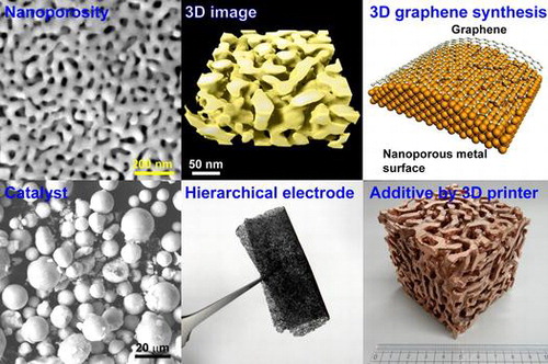
Nanoporous metals prepared via dealloying or selective leaching of solid solution alloys and compounds represent an emerging class of materials. They possess a three-dimensional (3D) structure of randomly interpenetrating ligaments/nanopores with sizes between 5 nm and several tens of micrometers, which can be tuned by varying their preparation conditions (such as dealloying time and temperature) or additional thermal coarsening. As compared to other nanostructured materials, nanoporous metals have many advantages, including their bicontinuous structure, tunable pore sizes, bulk form, good electrical conductivity, and high structural stability. Therefore, nanoporous metals represent ideal 3D materials with versatile functionality, which can be utilized in various fields. In this review, we describe the recent applications of nanoporous metals in molecular detection, catalysis, 3D graphene synthesis, hierarchical pore formation, and additive manufacturing (3D printing) together with our own achievements in these areas. Finally, we discuss possible ways of realizing the ultimate 3D functionality beyond the scope of nanoporous metals.
1. Introduction
Dealloying refers to selective leaching of one or more components out of a solid solution alloy or compound to produce a residual nanoporous structure [Citation1]. Recently, dealloying has been utilized as a facile method for fabricating nanoporous metals containing the three-dimensional (3D) bicontinuous structure characterized by open nanopores with tunable sizes. Hence, dealloyed nanoporous metals represent a new class of functional materials with large surface areas and unique structural properties such as mechanical rigidity, high electrical conductivity, and high corrosion resistance.
Interestingly, dealloying gold-copper alloy surfaces with natural acids (which is also called depletion gilding) was used in the ancient Incan Empire for coloring gems to shine gold [Citation2]. As another famous example, Raney nickel was obtained by dealloying nickel-aluminum alloy in 1927 [Citation3], but its microstructure and the related pore formation mechanism were not sufficiently studied at that time. First, Pickering and Swann investigated gold alloy corrosion via transmission electron microscopy (TEM) and obtained a nanoporous structure with pore sizes of around 10 nm [Citation4,5]. Second, A.J. Forty [Citation6] reported a TEM image of nanoporous gold (NPG) fabricated by dealloying AuAg alloy with nitric acid in Nature magazine in 1979 and proposed a possible mechanism of nanopore formation [Citation6], but his study has not attracted much attention for a long time. The dealloying technique was noticed by the scientific community when Erlebacher et al. [Citation7] proposed an atomistic model for nanoporosity evolution in Nature after conducting molecular dynamics simulations and studying the kinetics and potential dependence of the dealloying process, owing to the growing popularity of nanotechnology and nanoscience during that period (in 2001). As a result, subsequent studies in that area led to the creation of cross-interdisciplinary research fields related to batteries, catalysis, sensing, and biotechnology applications because nanoporous metals with excellent chemical and physical properties could be fabricated by this facile method [Citation8–10].
Using various dealloying techniques, many novel nanoporous metals have been produced. Thus, nanoporous Ag [Citation11], Pt [Citation12,13], Pd [Citation14], Ir [Citation15], Ni [Citation16–18], Cu [Citation19,20], Ti [Citation21], Ru [Citation22], and Au alloy [Citation23] were fabricated by dealloying AgAl, PtAl, PdCo, IrMg, NiMn, CuMn, TiSc, and RuMn alloys and multicomponent metallic glasses, respectively. Among these materials, NPG represents the most widely studied prototype of dealloyed nanoporous metals and one of the nanomaterials which can be easily fabricated in the chemical laboratory of a junior high school. Because inexpensive white gold leaves (12 carat, 50 wt.% Ag) are commonly available in leaf shops, their simple etching with nitric acid can be conducted at minimal cost [Citation24]. The pore sizes of the resulting materials were systematically studied by varying the dealloying conditions, such as acid concentration, applied potential [Citation25], dealloying temperature [Citation26], annealing treatment [Citation27], and reaction environment [Citation28–30]. The dealloying process is controlled by the diffusion of gold atoms at the alloy/electrolyte interface. Naturally low dealloying temperatures can significantly reduce the interfacial diffusivity of gold atoms and produce ultrafine NPG with a pore size of 5 nm [Citation26] (its representative 3D image visualized by electron tomography is displayed in Figure (a)). The skeletonized inter-connected gold ligaments, which exhibit a bicontinuous network, are shown in Figure (b). This metallic bicontinuous network distinguishes NPG from many other fragmented nanomaterials by its enhanced electrical conductivity and mechanical stability, which make it highly suitable for electrode fabrication. Interestingly, the analysis of 3D objects revealed that their area distributions of the convex and concave surfaces were identical; hence, their total mean curvature was equal to zero (this phenomenon is also observed for minimal surfaces in mathematics such as gyroids) [Citation31]. Owing to their bicontinuous structure, various core-shell nanoporous composites were fabricated using simple electrochemical and surface functionalization techniques such as electroplating, electroless plating, atomic layer deposition, and chemical vapor deposition (CVD). They included Au(core)/Ag(shell) [Citation32,33], Cu/Au [Citation34], Au/Pt [Citation35–39], Au/TiO2 [Citation40–42], Au/Al2O3 [Citation43], Au/MnO2 [Citation44,45], Au/SnO2(Sn) [Citation46], Au/RuO2 [Citation47], Au/MoS2 [Citation48,49], Au/polypyrrole [Citation50–52], and Au/polyaniline [Citation53–55] systems. As an example, a TEM image of the Au/Ag core-shell nanoporous composite with an Ag shell thickness of 2 nm is shown in Figure (c) [Citation32], while its 3D schematic is depicted in Figure (d). Thus, not only monolithic nanoporous metals, but also nanoporous composites embedded in other materials (metals, oxides, sulfides, and polymers) can be easily produced for various applications.
Figure 1. (a) A 3D image of NPG. (b) Skeletal network of the gold ligaments generated by using a 3D thinning algorithm. (c) A magnified TEM micrograph of the silver-plated NPG. (Adapted with permission from Ref. [Citation32]. Copyright (2008) American Chemical Society.) (d) A schematic diagram of the nanoporous metal core-shell structure. (Adapted with permission from Ref. [Citation63]. Copyright (2009) American Chemical Society.).
![Figure 1. (a) A 3D image of NPG. (b) Skeletal network of the gold ligaments generated by using a 3D thinning algorithm. (c) A magnified TEM micrograph of the silver-plated NPG. (Adapted with permission from Ref. [Citation32]. Copyright (2008) American Chemical Society.) (d) A schematic diagram of the nanoporous metal core-shell structure. (Adapted with permission from Ref. [Citation63]. Copyright (2009) American Chemical Society.).](/cms/asset/e18fcd64-5015-45c6-bdb6-7ae184cbd29d/tsta_a_1377047_f0001_oc.gif)
In this short review, we focus on the recent achievements describing the intriguing functionalities of nanoporous metals/composites as green materials. In particular, such areas as molecular detection, catalysis, 3D graphene synthesis, and hierarchical pore formation are discussed in detail, and the possibility of using these materials for additive manufacturing (AM) performed via 3D printing is evaluated. Finally, we propose feasible ways of realizing the ultimate 3D functionality of organic-inorganic hybrids beyond the scope of nanoporous metals.
2. Versatile applications
2.1. Molecular detection
Surface-enhanced Raman scattering (SERS) is a surface-sensitive technique where Raman scattering is enhanced by the molecular adsorption on rough metallic nanostructures via electromagnetic and chemical enhancement mechanisms [Citation56]. The chemical mechanism usually leads to the SERS enhancement with a factor of 102–103 depending on the orbital interactions between the metals and the adsorbed molecules, where charge transfer likely occurs during low-energy resonant Raman scattering [Citation57]. The electromagnetic mechanism characterized by a Raman enhancement factor of more than 1010 results from the excitation of surface plasmons in metallic nanostructures, which generates intense local electric fields (‘hot spots’) that strongly affect the optical properties of the adsorbate. Therefore, a major part of the SERS enhancement occurs via the electromagnetic mechanism. In order to detect individual molecules using a SERS-based technique, silver colloidal nanoparticles randomly deposited on glass or silicon substrates are usually utilized to tailor the size and population of the ‘hot spots’ [Citation58,59]. However, the main disadvantage of using silver nanoparticles is the poor reproducibility of their shapes and population on the substrate surface as well as the easy degradation in air due to oxidation.
After taking into account the difficulty of controlling the nanoparticle properties, freestanding NPG films can be considered facile substrates for SERS applications due to their tunable nanoporosity as well as the excellent chemical stability and biocompatibility of gold. For example, the SERS effect produced by the rhodamine 6G molecules adsorbed on the NPG surface with pore sizes ranging from 5 nm to 700 nm (which were tailored by the combination of low-temperature dealloying and annealing) has been systematically investigated [Citation27]. The obtained results reveal that the strongest SERS enhancement was achieved for the sample with an ultra-fine nanopore size of around 5 nm since the pores with smaller sizes produced larger signals. To elucidate the mechanism of the SERS enhancement, Lang et al. [Citation60] investigated the observed electromagnetic distribution via discrete dipole approximation simulations and concluded that the enhancement phenomenon mainly resulted from the presence of localized surface plasmons in nanoscaled Au ligaments and electromagnetic coupling between the neighboring ligaments (these plasmons can be detected using the energy-loss electron spectroscopy module of the TEM instrument due to the relatively small energy resolution of its electron beam (<0.3 eV); see Figure ). In general, the energy (frequency) distribution of surface plasmons depends strongly on the nanostructure geometry. For the NPG sample depicted in Figure , a plasmon with an energy of 1.3 eV is localized near the tip of the Au ligament, while another plasmon with an energy of 2.0 eV is localized near the neighboring ligament. Because of the presence of the randomly nanostructured Au network, such ‘hot spots’ with various plasmon frequencies (corresponding to a wide range of molecular detection) are uniformly distributed across the entire NPG film. To further enhance the observed SERS effect of ‘hot spots’, wrinkled NPG films were obtained by the thermal contraction of the underlying pre-strained polystyrene substrates (see Figure (a)) [Citation61]. Figure (b) shows scanning electron microscopy (SEM) images of the wrinkled NPG films on the glass substrates obtained at low and high magnifications, respectively. Figure (c) shows the photograph of the wrinkled nanoporous film with dimensions of 8 mm × 8 mm. As shown in Figure (d), these films contain a large number of cracks with nanogaps and nanotips along their edges, which significantly enhance the local electric fields. By further optimizing the Ag contents in NPG films, a detection limit of 10−12 M DNA adenine was ultimately achieved, which corresponded to the single-molecule detection level (see Figure (e)) [Citation62].
Figure 2. A STEM image of NPG obtained via low energy-loss electron spectroscopy. The region of interest (displayed in the inset) is denoted by the yellow square. The energy-loss images obtained at 1.3 and 2.0 eV are shown in order to visualize the corresponding surface plasmon energies.
Figure 3. (a) A schematic describing the preparation of wrinkled nanoporous films. (b) A microstructure of the wrinkled nanoporous film with a quasi-periodic wavelength of 10–15 μm. (c) A photograph of the wrinkled nanoporous film with dimensions of 8 mm × 8 mm. (d) A microstructure of the wrinkled ridges containing nanogaps, interleaving broken ligaments, and linear chains of self-similar nanocavities. (e) A single-molecule SERS spectrum of 10-12 M adenine solution with selected Raman bands. (Adapted from Ref. [Citation62]. Copyright Liu et al. (Citation2011)).
![Figure 3. (a) A schematic describing the preparation of wrinkled nanoporous films. (b) A microstructure of the wrinkled nanoporous film with a quasi-periodic wavelength of 10–15 μm. (c) A photograph of the wrinkled nanoporous film with dimensions of 8 mm × 8 mm. (d) A microstructure of the wrinkled ridges containing nanogaps, interleaving broken ligaments, and linear chains of self-similar nanocavities. (e) A single-molecule SERS spectrum of 10-12 M adenine solution with selected Raman bands. (Adapted from Ref. [Citation62]. Copyright Liu et al. (Citation2011)).](/cms/asset/2959f080-6964-45c5-a2fb-d88b2d5d6faf/tsta_a_1377047_f0003_oc.gif)
Since gold is one of the most expensive precious metals, the use of a nanoporous non-noble metal decorated with a thin layer of a noble metal should be considered for optical and catalytic applications. Owing to the potential applications of copper as an inexpensive raw material, nanoporous copper (NPC) was fabricated by dealloying Cu30Mn70 alloy [Citation19]. The systematic investigation of the obtained material revealed that the SERS inertness of Mn suppressed the SERS enhancement at very small nanopore sizes due to the increased residual concentration of Mn. In order to further improve the SERS performance of NPC, silver shells with tunable thicknesses were deposited in situ on the Cu ligament surfaces via a facile hydrometallurgical route [Citation63]. The resultant nanoporous composites exhibited significant improvement in their SERS properties by a factor of 16 as compared to those of the as-prepared NPC. Thus, biocompatible nanoporous metals with superior reproducibility and excellent chemical stability, which can be easily fabricated via a facile synthesis procedure, represent ideal SERS substrates for a wide range of applications in the fields of life science and environmental protection where molecule detection and identification are of critical importance.
2.2. Catalysis
Gold is considered a chemically inert material because its standard electrode potential is the highest among the metals (it is still possible to hear in the news that the ancient gold coins manufactured many centuries ago and recently found inside a sunken ship have retained their tantalizing gold color). However, gold nanoparticles deposited on oxide supports were found to be very active for CO oxidation at temperatures as low as -70 °C by Haruta et al. [Citation64] in 1987. The reason for the observed catalytic behavior of Au nanoparticles has been debated since that time, and the results of recent studies strongly suggest that the nanoparticle edges as well as the interface between the gold and the oxide phases contain active sites [Citation65–67]. According to the proposed mechanism, the CO molecules adsorbed on gold particles migrate toward the perimeter of the support oxide surface and react with adsorbed oxygen to form bidentate carbonate species. The detailed history of the studies on Au nanoparticles and role of the perimeter interfaces in their catalytic activity are summarized elsewhere [Citation68,69].
NPG contains no oxides or perimeter interfaces; however, it was also found to be catalytically active towards CO oxidation [Citation70,71], and the origin of its catalytic properties has been debated as well. In this respect, the NPG microstructure was characterized via spherical aberration-corrected (Cs-corrected) TEM [Citation72]. The atomic structure of the internal NPG surfaces (which are responsible for its catalytic activity) was examined using a scanning transmission electron microscope (STEM) equipped with a high-angle annual dark-field (HAADF) detector. The arrangement of the near-surface atoms was also determined with high accuracy by Cs-corrected high-resolution TEM (HRTEM), which provided phase-contrast images with high displacement sensitivity. From the results of extensive HRTEM and STEM characterizations, it was suggested that the superior catalytic performance of NPG originated from the surface strain and high concentration of low-coordination atoms stabilized by the complex geometry of bicontinuous NPG nanopores (see Figure (a)). After conducting STEM imaging along the [001], [101], and [112] zone axes of the face-centered cubic lattice of NPG ligaments, its reconstructed 3D atomic configuration was visualized by discrete tomography [Citation73]. The surface atoms with different coordination numbers were marked by various colors in Figure (b) to highlight the existing surface defects. As indicated by the results of statistical analysis, the fraction of the under-coordinated surface atoms on NPG ligaments was much larger than that on the truncated octahedral gold particles with identical diameters. These under-coordinated NPG surface atoms represent geometrically necessary surface defects and are kinetically more stable than the nanoparticle surface atoms. In addition to the static observations in an inert vacuum environment, we also characterized the evolution of the NPG atomic surface structure during the CO oxidation in a reactive atmosphere using a newly developed environmental HRTEM technique (Figure (c)). The NPG sample containing 1.2 at% of Ag begins to exhibit catalytic activity along with significant surface reconstruction at a pressure of several Pa (in addition, the {111} faceting dynamics along with the {011} surface can be clearly observed from the {011} direction [Citation72]). The obtained results indicate that the low-coordination atoms on the topmost NPG surface with a relatively high density are involved in the CO oxidation reaction as the catalytically active sites and represent the main source for the formation of the {111} facets. Since the residual Ag atoms may also play an important role in the CO oxidation reaction, a NPG sample containing around 20 at% of the residual Ag species with similar pore sizes has been fabricated. Interestingly, the {111} faceting dynamics is significantly suppressed during CO oxidation as compared to the process observed for the low-Ag NPG in the same environment, indicating that the presence of residual Ag atoms significantly stabilizes the surface steps and kinks of NPG. In summary, both the under-coordinated Au atoms and residual elements such as Ag appear to play important roles by providing high-energy binding sites for CO adsorption and catalytically active sites for the activation of molecular oxygen, respectively [Citation74].
Figure 4. (a) TEM (upper panel) and STEM (lower panel) images of NPG obtained at low and high magnifications, respectively. (b) Reconstructed 3D atomic configuration of the NPG ligament. Different colors denote the surface atoms with different coordination numbers. (c) An environmental TEM image of the rugged surface obtained during CO oxidation and in the absence of any reactions. Panels (a) and (c) are adapted from Ref. [Citation72]. © Macmillan Publishers Limited, Springer Nature. Panel (b) is adapted from Ref. [Citation73]. © WILEY-VCH Verlag GmbH & Co. KGaA, Weinheim.
![Figure 4. (a) TEM (upper panel) and STEM (lower panel) images of NPG obtained at low and high magnifications, respectively. (b) Reconstructed 3D atomic configuration of the NPG ligament. Different colors denote the surface atoms with different coordination numbers. (c) An environmental TEM image of the rugged surface obtained during CO oxidation and in the absence of any reactions. Panels (a) and (c) are adapted from Ref. [Citation72]. © Macmillan Publishers Limited, Springer Nature. Panel (b) is adapted from Ref. [Citation73]. © WILEY-VCH Verlag GmbH & Co. KGaA, Weinheim.](/cms/asset/818f8ed0-e7b2-4a1b-8636-87c366bb1e41/tsta_a_1377047_f0004_oc.gif)
Similar to the homogeneous Au catalysts, NPG was also utilized in heterogeneous organic reactions conducted under liquid-phase conditions. In 2010, Asao et al. [Citation75] reported for the first time the use of NPG for the conversion of silanes to silanols in acetone at ambient temperatures (other important organic reactions that can utilize NPG as a catalyst include semihydrogenation, hydrosilylation, diboration of alkynes, and benzannulation [Citation76]). More recently, NPG has been used as a highly chemoselective hydrogeneration agent for the reduction of terminal alkynes in the presence of internal alkynes, which could not be achieved previously using supported gold nanoparticle catalysts [Citation77]. The utilization of nanoporous copper also led to a significant enhancement of catalytic processes in the click chemistry without using any supports or bases [Citation78]. In addition, nanoporous Pd, which was fabricated by dealloying Pd30Ni50P20 metallic glass, exhibited remarkable catalytic activity for the Suzuki-coupling reaction between iodoarenes and arylboronic acids under mild conditions as well as for the Heck reaction of versatile aryl iodides and aryl bromides [Citation79,80].
Gas conversion in automobiles relies on the use of precious metal catalysts and rare-earth oxide supports fabricated from Pt, Pd, and CeO2. Lately, the consumption of Pt has grown significantly to meet the increasing demands of ground transportation in developing countries and various technologies utilized in developed countries such as fuel cells and water splitting [Citation81]. Hence, earth-abundant nanoporous CuNiMnO catalyst has been produced in our group by leaching Mn from CuNiMn alloy precursor [Citation82]. The resulting material was durable and catalytically active toward both NO reduction and CO oxidation. During catalytic reactions, its nanostructure self-transformed into a more active nanostructure with very active Cu/CuO regions, and its further significant coarsening was not accompanied since these regions were tangled with a stable nanoporous NiMnO network (see Figure (a)). This self-transformed nanostructure successfully completed a long-term durability test for 10-d NO reduction at 400 °C, and the TEM observations conducted in situ also provided evidence for its instantaneous reaction-induced transformation. A new concept of catalyst design drawn from this study is illustrated in Figure (b). The active metal layer tangled with nanoporous oxide is characterized by a high density of its perimeter interfaces as compared to those of the conventional nanoparticle/oxide systems. The monotonic nanopores do not exhibit sufficient heat resistance to suppress the pore degradation via coarsening; however, in this new design, despite the coarsening of the active metal regions to sizes exceeding 100 nm, they can preserve their perimeter interfaces as long as they remain inside the stable nanoporous oxide network. In the past, the mass production of nanoporous catalysts was rarely feasible. By now, cold-rolled foils, leaves, and melt-spun ribbons have been used as precursor alloys for basic studies; however, we found that the micro-powders with particle sizes below 50 μm produced by a gas-atomizing method are suitable for mass production. We demonstrated the large-scale fabrication of nanoporous CuNiMnO catalyst by leaching Cu15Ni15Mn70 gas-atomized powders (see Figures. (c) and (d)). The use of microalloyed powders can decrease the dealloying time and achieve more efficient productivity, which also provides additional ideas of material design toward realizing the ultimate 3D functionality (which will be discussed below).
Figure 5. (a) Microstructures of nanoporous CuNiMnO after NO reduction durability testing. The obtained STEM image and EDS chemical maps of the selected area show the distributions of Cu (red), Ni (green), Mn (blue), and O (orange) elements. (b) A schematic diagram of the new concept of catalyst design, in which the active metal is tangled with the nanoporous oxide. The described system exhibits higher density of the perimeter interfaces as compared to that in the conventional nanoparticle/oxide system. (c) A photograph of the mass-produced nanoporous CuNiMnO catalysts. (d) An SEM image of the gas-atomized micropowders after dealloying. Panels (a), (c), and (d) adapted from Ref. [Citation82]. © WILEY-VCH Verlag GmbH & Co. KGaA, Weinheim.
![Figure 5. (a) Microstructures of nanoporous CuNiMnO after NO reduction durability testing. The obtained STEM image and EDS chemical maps of the selected area show the distributions of Cu (red), Ni (green), Mn (blue), and O (orange) elements. (b) A schematic diagram of the new concept of catalyst design, in which the active metal is tangled with the nanoporous oxide. The described system exhibits higher density of the perimeter interfaces as compared to that in the conventional nanoparticle/oxide system. (c) A photograph of the mass-produced nanoporous CuNiMnO catalysts. (d) An SEM image of the gas-atomized micropowders after dealloying. Panels (a), (c), and (d) adapted from Ref. [Citation82]. © WILEY-VCH Verlag GmbH & Co. KGaA, Weinheim.](/cms/asset/48af723f-e040-4e1d-990f-e731606fe23d/tsta_a_1377047_f0005_oc.gif)
The reaction-driven transformation of porous nanostructures into active nanostructures is not limited to metals, but can also be applied to intermetallic and alloy compounds. Recently, Ni3Nb has evolved into a nanophase-separated structure consisting of the filamentous Ni networks with thicknesses below 10 nm incorporated into a niobium oxide matrix, whose nanostructure is capable of sustaining the thermal agglomeration during long-term NO reduction conducted at elevated temperatures [Citation83].
2.3. 3D graphene synthesis
Graphene represents a one atom thick sheet of graphite containing sp2-hybridized carbon atoms arranged in a hexagonal honeycomb lattice, which was isolated in 2004 by Andre Geim and Konstantin Novoselov using what was colloquially called a ‘scotch tape’ technique [Citation84,85]. Graphene intrinsically exhibits higher electron mobility as compared to that of any other known materials (which amounts to 200,000 cm2⋅V−1⋅s−1) due to the presence of massless particles called Dirac fermions [Citation86]. CVD is an inexpensive and facile method for the deposition of high-quality graphene layers on transition metal substrates such as Ni, Pd, Ru, Ir, and Cu [Citation87,88]. However, converting two-dimensional (2D) graphene sheets into stacked 3D graphene is not easy without decreasing its high electron mobility. Hence, high-quality 3D graphene was successfully synthesized by combining the CVD technique and templates fabricated from nanoporous transitional metals (such as Ni) [Citation89]. The nanoporous Ni has a bicontinuous structure consisting of a smooth robust surface and nanopores. Thus, uniform graphene films were grown across the nickel templates after heating in the CVD furnace filled with hydrogen, argon, and benzene gases. Subsequently, the nanoporous nickel template was removed by etching in acid, yielding a freestanding bicontinuous 3D structure of nanoporous graphene (its representative SEM and TEM images are shown in Figures (a) and (b), respectively [Citation90]). Interestingly, the 3D nanoporous graphene can preserve the distinctive 2D coherent electronic properties, as indicated by the results obtained via photoemission spectroscopy. After scaling its magnetotransport properties, which was performed using a semiclassical theory, the estimated carrier mobility of 3D graphene networks was equal to about 5000–7500 cm2 V−1 s−1, which was comparable to those of the CVD-grown flat 2D graphene sheets [Citation91]. More recently, strong tunable plasmonic absorption in the terahertz to mid-infrared regime with controllable doping levels and pore sizes was realized for fabricating novel plasmonic sensors due to the presence of intrinsic 2D Dirac plasmons in the 3D nanoporous graphene [Citation92].
Figure 6. (a) and (b) Representative SEM and TEM images of the 3D nanoporous graphene, respectively. (c) EELS chemical maps of the C, N, and S elemental distributions in the doped nanoporous graphene. (Adapted from Ref. [Citation90]. © Wiley-VCH Verlag GmbH & Co. KGaA, Weinheim.).
![Figure 6. (a) and (b) Representative SEM and TEM images of the 3D nanoporous graphene, respectively. (c) EELS chemical maps of the C, N, and S elemental distributions in the doped nanoporous graphene. (Adapted from Ref. [Citation90]. © Wiley-VCH Verlag GmbH & Co. KGaA, Weinheim.).](/cms/asset/8c219f97-6d04-487f-b69f-0ed35f59e09c/tsta_a_1377047_f0006_oc.gif)
Graphene by itself exhibits little catalytic activity because of its high chemical stability. Using the developed CVD technique for graphene growth, chemically active nanoporous graphene can be fabricated by replacing the benzene precursor with other compounds such as pyridine (C5H5 N), thiophene (C4H4S), and triphenylphosphine (Ph3P) for N, S, and P doping, respectively [Citation90,93,94]. It can potentially be used in electrocatalysis as a cathode electrode for the oxygen-reduction reactions of fuel cells [Citation94]. The other potential application of nanoporous graphene is replacing the Pt electrode utilized in the hydrogen evolution reaction (HER) in acid solutions for water splitting. Accordingly, the N and S co-doped nanoporous graphene was successfully used for the HER reaction, and the uniform distribution of dopants at the sub-nanoscale was confirmed via STEM-electron energy loss spectroscopy (EELS) analysis, as shown in Figure (c) [Citation90]. As indicated by the results of ab initio calculations, the dopant atoms were stabilized at the geometrically necessary structural defects of the hexagonal graphene lattice to preserve its porous structure. The obtained surface area was 800 m2/g, which was 500 times larger than that of flat graphene. Therefore, in the HER experiments, the onset potential of -0.2 V was able to maintain a much larger current density (as compared to that of flat graphene) due to the abundance of pores for mass transport and reactions occurring on both their internal and external surfaces that maximized the utilization of the available pore space. Currently, by further optimizing the amount of starting material for the nanoporous Ni temperate, contents of N, S, and P dopants as high as 6.4% were achieved [Citation93]. Such large amounts of synergistic dopants in the 3D nanoporous graphene structure resulted in a high density of active sites and, therefore, its superior catalytic performance toward high-efficiency electrochemical hydrogen production. Moreover, the nanoporous graphene containing single-atom nickel dopants exhibited superior HER catalytic properties in a 0.5 M H2SO4 solution with a low overpotential of approximately 50 mV and Tafel slope of 45 mV dec−1 as well as excellent cycling stability [Citation95]. Owing to these advantages, freestanding nanoporous graphene sheets can be directly installed into rechargeable Li-O2 batteries as feasible and economic cathode materials [Citation96]. More recently, high-performance Li-O2 batteries characterized by stable cycling at large capacities and low charge potentials have been fabricated in the forms of coin cells and pouches using tetrathiafulvalene redox additive and dimethyl sulfoxide-based electrolyte [Citation97]. In particular, the gravimetric capacity and energy density of the produced large-sized Li-O2 pouch batteries exceed those of the commercial Li-ion batteries.
The 3D nanoporous graphene does not exhibit the same light permeability as 2D graphene does, and its color is naturally black as indicated by the optical micrograph depicted in Figure (a) [Citation98]. The black object under solar illumination can be considered an economic heat source for generating high-energy steam since water heating via solar illumination is becoming the most common global application of solar energy. The materials utilized for heat localization must possess low specific heat, effective light absorption, low thermal conductivity, and open mesoscopic capillary porosity. Ideally, a single material should exhibit all the required thermal, optical, and wetting characteristics to avoid the interference from composite interfaces. By varying the level of nitrogen doping, pore size, and pore thicknesses, a single piece of porous N-doped 3D graphene with a thickness of around 35 μm can satisfy all the requirements and realize the conversion of sunlight to high-energy steam via heat localization at a high energy efficiency of 80% (in contrast to the magnitude of 53% obtained for the conventional graphite powders) because its sub-micrometer-sized pore channels are suitable for the capillary action of water. Moreover, nitrogen doping decreases the thermal conductivity of porous graphene, which is related to the bandgap widening via chemical doping and enhanced graphene wettability (the mechanism of steam generation by heat localization is described in Figures (b) and (c)). Such multifunctional abilities of the N-doped 3D graphene can be applied to the new utilization of sunlight and sewage purification for environmental cleanup [Citation98]. Thus, the open porous structure of 3D graphene characterized by bicontinuous porosity, tunable pore sizes, large surface area, high electron mobility, and tunable dopant levels can be widely used for various physical and chemical applications.
Figure 7. Steam generation by a thin porous graphene sheet. (a) An optical image of the piece of porous N-doped graphene sheet. (b) A schematic description of the heat localization system, which converts sunlight into steam using a piece of porous N-doped graphene as the steam generator. Thin porous graphene plays a versatile role in harvesting solar illumination as thermal energy. (c) An optical image of the steam generation process, in which the scrap from panel (b) is placed under the concentrated solar illumination. (Adapted from Ref. [Citation98]. © Wiley-VCH Verlag GmbH & Co. KGaA, Weinheim).
![Figure 7. Steam generation by a thin porous graphene sheet. (a) An optical image of the piece of porous N-doped graphene sheet. (b) A schematic description of the heat localization system, which converts sunlight into steam using a piece of porous N-doped graphene as the steam generator. Thin porous graphene plays a versatile role in harvesting solar illumination as thermal energy. (c) An optical image of the steam generation process, in which the scrap from panel (b) is placed under the concentrated solar illumination. (Adapted from Ref. [Citation98]. © Wiley-VCH Verlag GmbH & Co. KGaA, Weinheim).](/cms/asset/7c1bf454-5faf-4ed3-804f-d373682bebe9/tsta_a_1377047_f0007_oc.gif)
2.4. Hierarchical pore formation
Dealloyed nanoporous metals usually have unimodal pore sizes. Since nanopores (characterized by diameters below 1 μm) impede mass transport, and micropores (with sizes greater than 1 μm) can promote fast mass exchange, a hierarchical structure with various pore sizes can be utilized for smooth mass transport combined with a large surface area. Previously, some dealloying strategies have been proposed for building a hierarchical (bi-modal) porous structure (three of them are illustrated in Figure ). Ding and Erlebacher [Citation99] demonstrated the following dealloying/plating/re-dealloying technique. First, regular etching of an Au35Ag65 leaf was performed under corrosion-free conditions (corresponding to its floating on the surface of a concentrated nitric acid solution for 1 hour) followed by heat treatment. As a result, a structure with unimodal pore sizes of approximately 200–300 nm and residual Ag content of less than 5% was obtained. Next, an Ag layer was electrochemically deposited on the NPG surface, and NPG foil with relatively large pores was prepared by the second annealing (the latter re-homogenized the gold/silver elements, simultaneously increased the pore sizes, and produced the Ag-rich NPG structure). The final dealloying step dissolved the Ag species in the re-homogenized gold/silver alloy ligaments. Subsequently, to avoid the complicated Ag deposition procedure described by Ding and Erlebacher [Citation99], a new alloy precursor with a higher Ag content (Ag90Au10) was prepared (similar Ag-rich precursor alloys corresponding to 6 and 9 carat gold are commercially available in Italy and Germany). The initial short-term corrosion of such material creates a nanoporous Ag-rich Au alloy (similar to Au35Ag65), which is then thermally coarsened to form a porous alloy with pore sizes of around 200 nm corresponding to the upper hierarchical level. The second dealloying step removes the Ag species completely to reach a lower hierarchical level in the form of nanopores inside the larger ligaments [Citation100,101]. The representative SEM images obtained before and after the final dealloying steps of the second strategy are displayed in Figures (a) and (b), respectively [Citation102]. Finally, the bi-modal nanoporous structure can also be fabricated by dealloying two-phase precursors. Zhang et al. [Citation103] produced an Al-Au precursor alloy containing the primary Al phase and Al2Au intermetallic phase via rapid solidification. Al2Au dendrites first precipitated during the rapid solidification process followed by the formation of the α-Al solid solution phase from the remaining liquid. During dealloying, the fast excavation of the α-Al phase contributed to the formation of large-sized channels, and the slow dealloying of the Al2Au phase produced a nanoporous structure.
Figure 8. Three basic strategies (1–3) of the hierarchical pore fabrication via dealloying. The details of the corresponding procedures are explained in the main text.
Figure 9. SEM images of the hierarchical NPG. (a) Coarsened nanoporous AuAg alloy with a pore size of 80–100 nm. (b) Hierarchical NPG particles containing small pores with diameters of 5–20 nm on the surface of ligaments with sizes of 80–100 nm. (Adapted from Ref. [Citation102]. Copyright Guo et al (Citation2016)).
![Figure 9. SEM images of the hierarchical NPG. (a) Coarsened nanoporous AuAg alloy with a pore size of 80–100 nm. (b) Hierarchical NPG particles containing small pores with diameters of 5–20 nm on the surface of ligaments with sizes of 80–100 nm. (Adapted from Ref. [Citation102]. Copyright Guo et al (Citation2016)).](/cms/asset/bdc7abe7-a5ea-4dbb-9ccd-e9059668c34b/tsta_a_1377047_f0009_oc.gif)
Both the first and second strategies require the use of multiple electrochemical processes that are too costly and time-consuming for commercial-scale production. In the third strategy, a bi-modal nanoporous structure can be fabricated from two-phase precursors via one-step dealloying, but this approach also limits the utilized metal systems to two-phase precursors. Therefore, we have developed an innovative combination of the advanced powder metallurgy and dealloying to create hierarchical porous Au-Ag and Ni-Mn electrodes using Japanese ‘Washi’ paper as a template [Citation104]. As a result, a bi-modal porous structure was produced from metallized papers via one-step dealloying, while a tri-modal porous structure was fabricated for the first time through the two-step dealloying of Au-Ag. According to this strategy (illustrated in Figure (a)), pure metal and alloy powders are first prepared and collected by water atomization and filtering. After that, a template material consisting of cellulosic fibers with diameters less than 50 μm (Japanese ‘Washi’ paper) is filled with a slurry of metal powder (characterized by particle sizes of less than 5 μm) and water-soluble binder (the complete covering of the template surface is ensured by the capillary action). During high-temperature sintering, both the template material and carbon-based binder are decomposed, while the remaining metal powder becomes consolidated to form a sheet. If different pure metal powders are used in the slurry (such as Au and Ag ones), a solid solution alloy can be created. The described sintering technique is applicable to most metal powders and can be used for the net-shape mass production of ultra-thin microporous metal sheets. The subsequent one-step dealloying procedure removes the less noble elements, indicating that nanoscale pores can be created in metal sheets with pre-existing microscale porosity. The thin NiMn alloy sheet depicted in Figure (b) was sufficiently transparent to see the logo of Tohoku University printed on its reverse side with a high degree of mechanical flexibility retained even after the dealloying step (see Figure (c)). SEM images of the hierarchical nanoporous NiMn structure with a residual Mn content of around 20 at% are shown in Figure (d) (finer nanopores can be observed at a higher magnification). The results of TEM imaging revealed the presence of well-developed oxide compounds such as nickel hydrate Ni(OH)2 and manganese oxide (see Figure (e)). Such oxides are typically not observed in the images of conventional nanoporous Ni; hence, this phenomenon can be explained by the increase in the size of the micropores located between ligaments, which provides additional space for structural development. The BET surface area of the produced structure increased to 101 m2/g, which represents the highest value ever reported for nanoporous Ni. Because of its developed nanostructure, the hierarchical nanoporous NiMn electrode exhibits high electrochemical capacitance and oxygen evolution reaction activity. Instead of using ‘Washi’ paper, other commercially available templates (such as urethane) can be utilized for fabricating thick and robust microporous metals (see the SEM image depicted in Figure (f)). The Cu15Ni10Fe5Mn70 microporous metal displayed in the inset was industrially manufactured using a urethane template. After one-step dealloying, its hierarchical pore structure was realized. We believe that the described combination of the microporous alloy fabrication via powder metallurgy with subsequent dealloying can be easily applied to other alloy systems for the development of sensing devices, catalysts, and energy storage/conversion systems followed by their manufacture on an industrial scale.
Figure 10. (a) A schematic describing the creation of a hierarchical porous structure by sintering a slurry of metal powder mixed with water-soluble binder on a paper sheet. (b) A 50 μm thick Ni30Mn70 alloy sheet (the logo of Tohoku University is located on the reverse side). (c) A bendable thin dealloyed Ni30Mn70 alloy sheet. (d) SEM images of the Ni30Mn70 microporous nanostructure obtained after dealloying. (e) STEM image and chemical maps of the selected area containing the distributions of Ni (red), Mn (green), and O (blue) elements. (f) SEM images of the Cu15Ni10Fe5Mn70 microporous metal alloy (shown in the inset) obtained after dealloying. (Panels (a)–(e) are adapted from Ref. [Citation104]. Copyright Fujita et al. (Citation2015)).
![Figure 10. (a) A schematic describing the creation of a hierarchical porous structure by sintering a slurry of metal powder mixed with water-soluble binder on a paper sheet. (b) A 50 μm thick Ni30Mn70 alloy sheet (the logo of Tohoku University is located on the reverse side). (c) A bendable thin dealloyed Ni30Mn70 alloy sheet. (d) SEM images of the Ni30Mn70 microporous nanostructure obtained after dealloying. (e) STEM image and chemical maps of the selected area containing the distributions of Ni (red), Mn (green), and O (blue) elements. (f) SEM images of the Cu15Ni10Fe5Mn70 microporous metal alloy (shown in the inset) obtained after dealloying. (Panels (a)–(e) are adapted from Ref. [Citation104]. Copyright Fujita et al. (Citation2015)).](/cms/asset/17faa231-cea2-4731-829a-9fe54f77f342/tsta_a_1377047_f0010_oc.gif)
2.5. Additive manufacturing via 3D printing
The AM technique (known as 3D printing) has been developing very rapidly. It allows building 3D objects from powder, wires, or sheets in a layer-by-layer manner. Today, the related methods for manufacturing metal objects are represented by selective laser melting or electron beam melting. Sames et al. [Citation105] compare various metal AM techniques, and their strengths and limitations are discussed. The main drawback of the AM approach is a very limited number of applicable alloy systems; thus, suitable commercially available materials include steels, stainless steels, structural aerospace material (Ti–6Al–4V), bio-compatible implant materials (such as Ti, Ti–6Al–4V, and CoCr), and high-temperature materials (Inconel 626, Inconel 718) for high-impact industries. Another drawback of metal AM is its very high input costs (including those of the hardware, feedstock, and maintenance), which currently limit its scope of applications to academic researchers. Owing to recent advancements in this area, a novel AM system that is capable of processing different metal powders simultaneously to produce ‘colorful’ objects has been developed (but not yet commercialized) by JEOL [Citation106], while the majority of other AM systems can only use one type of metal powders to fabricate ‘monotone’ objects.
As has been discussed above, the dealloyed gas-atomized nanoporous microsphere can be considered a functionalized microstructural ‘element’ for many purposes; therefore, it can also be added to virtually any object. For example, Cu30Mn70 spherical powder was mixed with a commercially available dispersion of cellulose nanofibers; as a result, a piece of paper containing embedded nanoporous copper spheres was fabricated after the subsequent drying and etching steps, as demonstrated in Figure (a). Such paper can be further transformed into a novel 3D shape using either an origami or kirigami technique, which has been extensively studied in recent years [Citation107,108]. In order to evaluate the ability of the modern AM techniques to fabricate porous objects, a gyroid-type porous structure was obtained from Ti–6Al–4V alloy, as shown in Figure (b) (the gyroid shape was selected since it possessed a unique pore structure and could be described by the simple mathematical equation sinxcony + sinycosz + sinzcosx = 0). Unfortunately, we were unable to utilize our alloy powders instead of Ti alloys for the external metal AM systems because they could cause serious contamination (it is virtually impossible to use the newly developed alloy powders without owning an expensive AM system with the initial cost of more than $1 million). However, despite the extremely high costs of the modern metal AM systems (which significantly exceed the typical budget of an academic researcher), other AM-related techniques such as stereolithography (SL) can be used. The SL method involves the layer-by-layer conversion of liquid resins into solid cross-sections using an ultraviolet laser and continues to remain one of the most widely used rapid prototyping techniques for plastic models. Therefore, we have attempted to mix our prepared Cu30Mn70 alloy powders with a liquid resin to fabricate a structure mimicking random porous features via SL; as a result, a porous copper microsphere was clearly observed on the surface of the etched specimen, as shown in Figure (c). We are currently investigating possible inexpensive AM methods for fabricating solid hierarchical porous structures for various applications.
Figure 11. (a) A SEM image of the nanoporous Cu microspheres dispersed among the cellulose nanofibers. (b) A photograph of the gyroid shapes fabricated from acrylonitrile butadiene styrene (ABS) resin (left) and Ti–6Al–4V alloy (right). (c) A photograph of the randomly selected porous ABS resin composited with dispersed nanoporous Cu microspheres. The SEM surface images were obtained both at low and high magnifications.
3. Perspectives
Following a long trail from ancient times to modern civilization, nanoporous metals have been established as a novel class of materials. In this review, we have discussed the attractive features of nanoporous metals as well as the achievements of our research group in this field. However, many unexplored topics remain to be investigated. For example, dealloying by metallic melt was reported by Wada et al. [Citation109] in 2011. This technique can be applied to the preparation of nanoporous less noble metals and non-metals such as Ti [Citation109], Nb [Citation110], Si [Citation111], Fe [Citation112], and Cr [Citation112] as well as graphite [Citation113], ferritic stainless steel (Fe-Cr) [Citation112], and β-Ti (Ti-Cr-Zr) alloy [Citation114], whose dealloying mechanism is described in detail elsewhere [Citation115]. In particular, the nanoporous Si obtained by this method can be used for fabricating high-quality anodes with a high lithium capacity approaching its theoretical limit and significantly extended service lives, which are comparable with those of the electrodes manufactured from silicon nanoparticles [Citation111,116]. Moreover, NPG is an extraordinarily well-defined model system for studying the mechanical behavior of metal nanostructures, and its deformation mechanism as well as the ligament size effect on the yield strength have been extensively investigated both experimentally and theoretically [Citation117].
The future outlook toward achieving the ultimate 3D functionality is summarized in Figure . Similar to periodic tables, it is very interesting to note that the nanoporous microsphere dealloyed from gas-atomized powders can be considered a mere example of functional ‘elements’ among many other novel microstructures (including living cells). Various characteristic microstructures (including those of superalloys, superconductors, shape memory alloys, and metallic glasses) are widely known, and their powders with unique functionalities for 3D printers can be fabricated. The development of the 3D printing technology for medicine is proceeding very rapidly, and multiple powders/cells will be able to be simultaneously integrated with high precision very soon. The key issues here are the selection of a proper method for designing 3D objects with desired properties and the exact positioning of the required functional elements in the resulting 3D structure. A possible solution to these problems can be obtained using recent advances in the field of information technology. Similar to 3D printing technology, the fields of superior artificial intelligence (AI) [Citation118,119], neuromorphic devices [Citation120,121], and data informatics (represented by the ‘big data’ collected for various materials, cells, and DNA [Citation122,123]) are also progressing beyond our current level of knowledge. It remains an open question: what and how can the ultimate AI learn from the Big Data design via AI-driven 3D printing? Similar to our human body containing hierarchical blood vessels, the AI may design a combination of hierarchical nanoporous metals for fluid channels, catalysts, electrolytes, cooperative cells, and self-heating ceramics to ultimately create an artificial life (AL) in the future: in other words, ‘AI begets AL’.
Figure 12. Future perspective: toward achieving the ultimate 3D functionality based on the concept of the ‘functional elements of microstructure’, which is similar to periodic tables. A super 3D printing technology powered by the ultimate AI might discover the long-sought organic-inorganic hybrids that represent ‘life’.
Funding
This study was mainly supported by the JST-PRESTO program ‘New Materials Science and Element Strategy’ and research funds provided by the ‘World Premier International (WPI) Research Center Initiative for Atoms, Molecules and Materials’, MEXT (Japan). It was also partially supported by KAKENHI [grant numbers JP15K13796, JP16H02293, and JP17H06220] and the JST-CREST program ‘Innovative Catalysts and Creation Technologies for the Utilization of Diverse Natural Carbon Resources’ [grant number JPMJCR15P1].
Disclosure statement
No potential conflict of interest was reported by the author.
Acknowledgements
The author acknowledges the assistance provided by the Advanced Characterization Nanotechnology Platform of the High-Voltage Electron Microscopy Laboratory at the Nagoya University. In addition, we appreciate the kind support of Mingwei Chen, Yoshikazu Ito, Akihito Hirata, Juihui Han, Natsuhiko Yoshinaga, and the other lab members from the Tohoku University, Hideki Abe from NIMS, Yasuhiro Okunishi from JEOL, and Nagamine Manufacturing Co. Ltd.
Related Research Data
References
- Weissmuller J, Newman RC, Jin HJ, et al. Nanoporous metals by alloy corrosion: formation and mechanical properties. MRS Bull. 2009;34:577–586.10.1557/mrs2009.157
- Newman RC, Corcoran SG, Erlebacher J, et al. Alloy corrosion. MRS Bull. 1999;24(7):24–28.10.1557/S0883769400052660
- Raney M, inventor. Method of producing finely-divided nickel. United States patent US 1,628,190. 1927 May 10.
- Pickering HW, Swann PR. Electron metallography of chemical attack upon some alloys susceptible to stress corrosion cracking. Corrosion. 1963;19:373–389.10.5006/0010-9312-19.11.373
- Swann PR. Mechanism of corrosion tunneling with special reference to Cu3Au. Corrosion. 1969;25:147–150.
- Forty AJ. Corrosion micromorphology of noble metal alloys and depletion gilding. Nature. 1979;282:597–598.10.1038/282597a0
- Erlebacher J, Aziz MJ, Karma A, et al. Evolution of nanoporosity in dealloying. Nature. 2001;410:450–453.10.1038/35068529
- Ding Y, Chen MW. Nanoporous metals for catalytic and optical applications. MRS Bull. 2009;34:569–576.10.1557/mrs2009.156
- Qiu HJ, Li X, Xu HT, et al. Nanoporous metal as a platform for electrochemical and optical sensing. J Mater Chem C. 2014;2:9788–9799.10.1039/C4TC01913 J
- Qiu HJ, Xu HT, Liu L, et al. Correlation of the structure and applications of dealloyed nanoporous metals in catalysis and energy conversion/storage. Nanoscale. 2015;7:386–400.10.1039/C4NR05778C
- Detsi E, Vukovic Z, Punzhin S, et al. Fine-tuning the feature size of nanoporous silver. Cryst Eng Comm. 2012;14:5402–5406.10.1039/c2ce25313e
- Zhang ZH, Wang Y, Qi Z, et al. Generalized fabrication of nanoporous metals (Au, Pd, Pt, Ag, and Cu) through chemical dealloying. J Phys Chem C. 2009;113:12629–12636.10.1021/jp811445a
- Qiu HJ, Shen X, Wang JQ, et al. Aligned nanoporous Pt-Cu bimetallic microwires with high catalytic activity toward methanol electrooxidation. ACS Catal. 2015;5:3779–3785.10.1021/acscatal.5b00073
- Hakamada M, Nakano H, Furukawa T, et al. Hydrogen storage properties of nanoporous palladium fabricated by dealloying. J Phys Chem C. 2010;114:868–873.10.1021/jp909479 m
- Wang L, Briot NJ, Swartzentruber PD, et al. Magnesium alloy precursor thin films for efficient, practical fabrication of nanoporous metals. Metall Mat Trans A. 2014;45:1–5.10.1007/s11661-013-2127-7
- Hakamada M, Takahashi M, Furukawa T, et al. Coercivity of nanoporous Ni produced by dealloying. Appl Phys Lett. 2009;94:153105.10.1063/1.3119663
- Hakamada M, Mabuchi M. Preparation of nanoporous Ni and Ni-Cu by dealloying of rolled Ni-Mn and Ni-Cu-Mn alloys. J Alloys Compd. 2009;485:583–587.10.1016/j.jallcom.2009.06.031
- Qiu HJ, Kang JL, Liu P, et al. Fabrication of large-scale nanoporous nickel with a tunable pore size for energy storage. J Power Sources. 2014;247:896–905.10.1016/j.jpowsour.2013.08.070
- Chen LY, Yu JS, Fujita T, et al. Nanoporous copper with tunable nanoporosity for SERS applications. Adv Funct Mater. 2009;19:1221–1226.10.1002/adfm.v19:8
- Hayes JR, Hodge AM, Biener J, et al. Monolithic nanoporous copper by dealloying Mn-Cu. J Mater Res. 2006;21:2611–2616.10.1557/jmr.2006.0322
- Panagiotopoulos NT, Jorge AM, Rebai I, et al. Nanoporous titanium obtained from a spinodally decomposed Ti alloy. Microporous Mesoporous Mater. 2016;222:23–26.10.1016/j.micromeso.2015.09.054
- Hakamada M, Motomura J, Hirashima F, et al. Preparation of nanoporous ruthenium catalyst and its CO oxidation characteristics. Mater Trans. 2012;53:524–530.10.2320/matertrans.M2011326
- Yu J, Ding Y, Xu C, et al. Nanoporous metals by dealloying multicomponent metallic glasses. Chem Mater. 2008;20:4548–4550.10.1021/cm8009644
- Ding Y, Kim YJ, Erlebacher J. Nanoporous gold leaf: ‘Ancient technology’/advanced material. Adv Mater. 2004;16:1897–1900.10.1002/(ISSN)1521-4095
- Senior NA, Newman RC. Synthesis of tough nanoporous metals by controlled electrolytic dealloying. Nanotechnology. 2006;17:2311–2316.10.1088/0957-4484/17/9/040
- Qian LH, Chen MW. Ultrafine nanoporous gold by low-temperature dealloying and kinetics of nanopore formation. Appl Phys Lett. 2007;91:083105.10.1063/1.2773757
- Qian LH, Yan XQ, Fujita T, et al. Surface enhanced Raman scattering of nanoporous gold: smaller pore sizes stronger enhancements. Appl Phys Lett. 2007;90:153120.10.1063/1.2722199
- Kuwano-Nakatani S, Fujita T, Uchisawa K, et al. Environment-sensitive thermal coarsening of nanoporous gold. Mater Trans. 2015;56:468–472.10.2320/matertrans.MF201403
- Chen AY, Shi SS, Liu F, et al. Effect of annealing atmosphere on the thermal coarsening of nanoporous gold films. Appl Surf Sci. 2015;355:133–138.10.1016/j.apsusc.2015.07.065
- Sun Y, Burger SA, Balk TJ. Controlled ligament coarsening in nanoporous gold by annealing in vacuum versus nitrogen. Philos Mag. 2014;94:1001–1011.10.1080/14786435.2013.876113
- Fujita T, Qian LH, Inoke K, et al. Three-dimensional morphology of nanoporous gold. Appl Phys Lett. 2008;92:251902.10.1063/1.2948902
- Qian LH, Ding Y, Fujita T, et al. Synthesis and optical properties of three-dimensional porous core-shell nanoarchitectures. Langmuir. 2008;24:4426–4429.10.1021/la703621c
- Yang M, Zhang L, Chen B, et al. Silver nanoparticles decorated nanoporous gold for surface-enhanced Raman scattering. Nanotechnology. 2017;28:055301.10.1088/1361-6528/28/5/055301
- Chen LY, Fujita T, Ding Y, et al. A three-dimensional gold-decorated nanoporous copper core-shell composite for electrocatalysis and nonenzymatic biosensing. Adv Funct Mater. 2010;20:2279–2285.10.1002/adfm.v20:14
- Ding Y, Chen MW, Erlebacher J. Metallic mesoporous nanocomposites for electrocatalysis. J Am Chem Soc. 2004;126:6876–6877.10.1021/ja0320119
- Zeis R, Mathur A, Fritz G, et al. Platinum-plated nanoporous gold: an efficient, low Pt loading electrocatalyst for PEM fuel cells. J Power Sources. 2007;165:65–72.10.1016/j.jpowsour.2006.12.007
- Xiao S, Xiao F, Hu Y, et al. Hierarchical nanoporous gold-platinum with heterogeneous interfaces for methanol electrooxidation. Sci Rep. 2014;4:4370.
- Kiani A, Hatami S. Fabrication of platinum coated nanoporous gold film electrode: a nanostructured ultra low-platinum loading electrocatalyst for hydrogen evolution reaction. Int J Hydrog Energy. 2010;35:5202–5209.10.1016/j.ijhydene.2010.03.014
- Du Y, Xu JJ, Chen HY. Ultrathin platinum film covered high-surface-area nanoporous gold for methanol electro-oxidation. Electrochem Commun. 2009;11:1717–1720.10.1016/j.elecom.2009.07.004
- Jia C, Yin H, Ma H, et al. Enhanced photoelectrocatalytic activity of methanol oxidation on TiO2-decorated nanoporous gold. J Phys Chem C. 2009;113:16138–16143.10.1021/jp904191 k
- Kudo A, Fujita T, Lang X, et al. Enhanced electrochemical performances of nanoporous gold by surface modification of titanium dioxide nanoparticles. Mater Trans. 2010;51:1566–1569.10.2320/matertrans.MAW201014
- Chen AY, Shi SS, Wang JW, et al. Microstructure and electrocatalytic performance of nanoporous gold foils decorated by TiO2 coatings. Surf Coat Technol. 2016;286:113–118.10.1016/j.surfcoat.2015.10.014
- Biener MM, Biener J, Wichmann A, et al. ALD functionalized nanoporous gold: thermal stability, mechanical properties, and catalytic activity. Nano Lett. 2011;11:3085–3090.10.1021/nl200993 g
- Lang X, Hirata A, Fujita T, et al. Nanoporous metal/oxide hybrid electrodes for electrochemical supercapacitors. Nat Nanotech. 2011;6:232–236.10.1038/nnano.2011.13
- Kang J, Chen L, Hou Y, et al. Electroplated thick manganese oxide films with ultrahigh capacitance. Adv Energy Mater. 2013;3:857–863.10.1002/aenm.v3.7
- Yu Y, Gu L, Lang X, et al. Li storage in 3D nanoporous Au-supported nanocrystalline tin. Adv Mater. 2011;23:2443–2447.10.1002/adma.201004331
- Chen LY, Hou Y, Kang JL, et al. Toward the theoretical capacitance of RuO2 reinforced by highly conductive nanoporous gold. Adv Energy Mater. 2013;3:851–856.10.1002/aenm.v3.7
- Ge X, Chen L, Zhang L, et al. Nanoporous metal enhanced catalytic activities of amorphous molybdenum sulfide for high-efficiency hydrogen production. Adv Mater. 2014;26:3100–3104.10.1002/adma.201305678
- Tan Y, Liu P, Chen L, et al. Monolayer MoS2 films supported by 3D nanoporous metals for high-efficiency electrocatalytic hydrogen production. Adv Mater. 2014;26:8023–8028.10.1002/adma.v26.47
- Hou Y, Chen L, Zhang L, et al. Ultrahigh capacitance of nanoporous metal enhanced conductive polymer pseudocapacitors. J Power Sources. 2013;225:304–310.10.1016/j.jpowsour.2012.10.067
- Hou Y, Chen L, Liu P, et al. Nanoporous metal based flexible asymmetric pseudocapacitors. J Mater Chem A. 2014;2:10910–10916.10.1039/C4TA00969 J
- Wang K, Stenner C, Weissmüller J. A nanoporous gold-polypyrrole hybrid nanomaterial for actuation. Sens Actuators B: Chem. 2017;248:622–629.10.1016/j.snb.2017.04.025
- Lang X, Zhang L, Fujita T, et al. Three-dimensional bicontinuous nanoporous Au/polyaniline hybrid films for high-performance electrochemical supercapacitors. J Power Sources. 2012;197:325–329.10.1016/j.jpowsour.2011.09.006
- Meng F, Ding Y. Sub-micrometer-thick all-solid-state supercapacitors with high power and energy densities. Adv Mater. 2011;23:4098–4102.10.1002/adma.v23.35
- Detsi E, Onck P, De Hosson JTM. Metallic muscles at work: high rate actuation in nanoporous gold/polyaniline composites. ACS Nano. 2013;7:4299–4306.10.1021/nn400803x
- Moskovits M. Surface-enhanced spectroscopy. Rev Mod Phys. 1985;57:783–826.10.1103/RevModPhys.57.783
- Michaels AM, Jiang J, Brus L. Ag nanocrystal junctions as the site for surface-enhanced Raman scattering of single rhodamine 6G molecules. J Phys Chem B. 2000;104:11965–11971.10.1021/jp0025476
- Wiley BJ, Im SH, Li ZY, et al. Maneuvering the surface plasmon resonance of silver nanostructures through shape-controlled synthesis. J Phys Chem B. 2006;110:15666–15675.10.1021/jp0608628
- Mikac L, Ivanda M, Gotic M, et al. Synthesis and characterization of silver colloidal nanoparticles with different coatings for SERS application. J Nanopart Res. 2014;16:451.10.1007/s11051-014-2748-9
- Lang XY, Guan PF, Zhang L, et al. Characteristic length and temperature dependence of surface enhanced Raman scattering of nanoporous gold. J Phys Chem C. 2009;113:10956–10961.10.1021/jp903137n
- Zhang L, Lang X, Hirata A, et al. Wrinkled nanoporous gold films with ultrahigh surface-enhanced Raman scattering enhancement. ACS Nano. 2011;5:4407–4413.10.1021/nn201443p
- Liu H, Zhang L, Lang X, et al. Single molecule detection from a large-scale SERS-active Au79Ag21 substrate. Sci Rep. 2011;1:1102.10.1038/srep00112
- Chen LY, Zhang L, Fujita T, et al. Surface-enhanced Raman scattering of silver@nanoporous copper core-shell composites synthesized by an in situ sacrificial template approach. J Phys Chem C. 2009;113:14195–14199.10.1021/jp904081s
- Haruta M, Kobayashi T, Sano H, et al. Novel gold catalysts for the oxidation of carbon-monoxide at a temperature far below 0 °C. Chem Lett. 1987;16:405–408.10.1246/cl.1987.405
- Fujitani T, Nakamura I, Akita T, et al. Hydrogen dissociation by gold clusters. Angew Chem Int Ed. 2009;48:9515–9518.10.1002/anie.200905380
- Fujitani T, Nakamura I. Mechanism and active sites of the oxidation of CO over Au/TiO2. Angew Chem Int Ed. 2011;50:10144–10147.10.1002/anie.201104694
- Cargnello M, Doan-Nguyen VVT, Gordon TR, et al. Control of metal nanocrystal size reveals metal-support interface role for ceria catalysts. Science. 2013;341:771–773.10.1126/science.1240148
- Takei T, Akita T, Nakamura I, et al. Heterogeneous catalysis by gold. Adv Catal. 2012;55:1–126.
- Haruta M. Role of perimeter interfaces in catalysis by gold nanoparticles. Faraday Discuss. 2011;152:11–32.10.1039/c1fd00107 h
- Xu C, Su J, Xu X, et al. Low temperature CO oxidation over unsupported nanoporous gold. J Am Chem Soc. 2007;129:42–43.10.1021/ja0675503
- Zielasek V, Jürgens B, Schulz C, et al. Gold catalysts: nanoporous gold foams. Angew Chem Int Ed. 2006;45:8241–8244.10.1002/(ISSN)1521-3773
- Fujita T, Guan P, McKenna K, et al. Atomic origins of the high catalytic activity of nanoporous gold. Nat Mater. 2012;11:775–780.10.1038/nmat3391
- Liu P, Guan P, Hirata A, et al. Visualizing under-coordinated surface atoms on 3D nanoporous gold catalysts. Adv Mater. 2016;28:1753–1759.10.1002/adma.201504032
- Biener J, Biener MM, Madix RJ, et al. Nanoporous gold: understanding the origin of the reactivity of a 21st century catalyst made by pre-Columbian technology. ACS Catal. 2015;5:6263–6270.10.1021/acscatal.5b01586
- Asao N, Ishikawa Y, Hatakeyama N, et al. Nanostructured materials as catalysts: nanoporous-gold-catalyzed oxidation of organosilanes with water. Angew Chem Int Ed. 2010;49:10093–10095.10.1002/anie.201005138
- Takale BS, Bao M, Yamamoto Y. Gold nanoparticle (AuNPs) and gold nanopore (AuNPore) catalysts in organic synthesis. Org Biomol Chem. 2014;12:2005–2027.10.1039/c3ob42207 k
- Takale BS, Feng X, Lu Y, et al. Unsupported nanoporous gold catalyst for chemoselective hydrogenation reactions under low pressure: effect of residual silver on the reaction. J Am Chem Soc. 2016;138:10356–10364.10.1021/jacs.6b06569
- Jin T, Yan M, Menggenbateer, et al. Nanoporous copper metal catalyst in click chemistry: nanoporosity-dependent activity without supports and bases. Adv Synth Catal. 2011;353:3095–3100.10.1002/adsc.v353.17
- Tanaka S, Kaneko T, Asao N, et al. A nanostructured skeleton catalyst: Suzuki-coupling with a reusable and sustainable nanoporous metallic glass Pd-catalyst. Chem Commun. 2011;47:5985–5987.10.1039/c1cc10710 k
- Kaneko T, Tanaka S, Asao N, et al. Reusable and sustainable nanostructured skeleton catalyst: Heck reaction with nanoporous metallic glass Pd (PdNPore) as a support, stabilizer and ligand-free catalyst. Adv Synth Catal. 2011;353:2927–2932.10.1002/adsc.v353.16
- Abe H. Current status and future of the car exhaust catalyst should aim for ~ Tsukuba Innovation Arena (TIA): outline and Outlook ~. Sci Technol Trends Q Rev. 2011;039:21–31.
- Fujita T, Abe H, Tanabe T, et al. Earth-abundant and durable nanoporous catalyst for exhaust-gas conversion. Adv Funct Mater. 2016;26:1609–1616.10.1002/adfm.v26.10
- Tanabe T, Imai T, Tokunaga T, et al. Nanophase-separated Ni3Nb as an automobile exhaust catalyst. Chem Sci. 2017;8:3374–3378.10.1039/C6SC05473 K
- Novoselov KS, Geim AK, Morozov SV, et al. Electric field effect in atomically thin carbon films. Science. 2004;306:666–669.10.1126/science.1102896
- Geim AK. Random walk to graphene (Nobel Lecture). Angew Chem Int Ed. 2011;50:6966–6985.10.1002/anie.v50.31
- Auton G, Zhang J, Kumar RK, et al. Graphene ballistic nano-rectifier with very high responsivity. Nat Commun. 2016;7:11670.10.1038/ncomms11670
- Zhang Y, Zhang L, Zhou C. Review of chemical vapor deposition of graphene and related applications. Acc Chem Res. 2013;46:2329–2339.10.1021/ar300203n
- Mattevi C, Kim H, Chhowalla M. A review of chemical vapour deposition of graphene on copper. J Mater Chem. 2011;21:3324–3334.10.1039/C0JM02126A
- Ito Y, Tanabe Y, Qiu HJ, et al. High-quality three-dimensional nanoporous graphene. Angew Chem Int Ed. 2014;53:4822–4826.10.1002/anie.201402662
- Ito Y, Cong W, Fujita T, et al. High catalytic activity of nitrogen and sulfur co-doped nanoporous graphene in the hydrogen evolution reaction. Angew Chem Int Ed. 2015;54:2131–2136.10.1002/anie.201410050
- Tanabe Y, Ito Y, Sugawara K, et al. Electric properties of Dirac fermions captured into 3D nanoporous graphene networks. Adv Mater. 2016;28:10304–10310.10.1002/adma.201601067
- D’Apuzzo F, Piacenti AR, Giorgianni F, et al. Terahertz and mid-infrared plasmons in three-dimensional nanoporous graphene. Nat Commun. 2017;8:14885.10.1038/ncomms14885
- Ito Y, Shen Y, Hojo D, et al. Correlation between chemical dopants and topological defects in catalytically active nanoporous graphene. Adv Mater. 2016;28:10644–10651.10.1002/adma.201604318
- Ito Y, Qiu HJ, Fujita T, et al. Bicontinuous nanoporous N-doped graphene for the oxygen reduction reaction. Adv Mater. 2014;26:4145–4150.10.1002/adma.v26.24
- Qiu HJ, Ito Y, Cong WT, et al. Nanoporous graphene with single-atom nickel dopants: an efficient and stable catalyst for electrochemical hydrogen production. Angew Chem Int Ed. 2015;54:14031–14035.10.1002/anie.201507381
- Han J, Guo X, Ito Y, et al. Effect of chemical doping on cathodic performance of bicontinuous nanoporous graphene for Li-O2 batteries. Adv Energy Mater. 2016;6:1501870.10.1002/aenm.201501870
- Han J, Huang G, Ito Y, et al. Full performance nanoporous graphene based Li-O2 batteries through solution phase oxygen reduction and redox-additive mediated Li2O2 oxidation. Adv Energy Mater. 2017;7:1601933.10.1002/aenm.v7.7
- Ito Y, Tanabe Y, Han J, et al. Multifunctional porous graphene for high-efficiency steam generation by heat localization. Adv Mater. 2015;27:4302–4307.10.1002/adma.v27.29
- Ding Y, Erlebacher J. Nanoporous metals with controlled multimodal pore size distribution. J Am Chem Soc. 2003;125:7772–7773.10.1021/ja035318 g
- Qi Z, Weissmüller J. Hierarchical nested-network nanostructure by dealloying. ACS Nano. 2013;7:5948–5954.10.1021/nn4021345
- Qi Z, Vainio U, Kornowski A, et al. Porous gold with a nested-network architecture and ultrafine structure. Adv Funct Mater. 2015;25:2530–2536.10.1002/adfm.201404544
- Guo X, Han J, Liu P, et al. Hierarchical nanoporosity enhanced reversible capacity of bicontinuous nanoporous metal based Li-O2 battery. Sci Rep. 2016;6:19.10.1038/srep33466
- Zhang Z, Wang Y, Qi Z, et al. Nanoporous gold ribbons with bimodal channel size distributions by chemical dealloying of Al-Au alloys. J Phys Chem C. 2009;113:1308–1314.10.1021/jp808569 g
- Fujita T, Kanoko Y, Ito Y, et al. Nanoporous metal papers for scalable hierarchical electrode. Adv Sci. 2015;2:1500086.10.1002/advs.201500086
- Sames WJ, List FA, Pannala S, et al. The metallurgy and processing science of metal additive manufacturing. Int Mater Rev. 2016;61:315–360.10.1080/09506608.2015.1116649
- Japanese Unexamined Patent Application Publication No. 2015-193866.
- Peraza-Hernandez EA, Hartl DJ, Malak RJ, et al. Origami-inspired active structures: a synthesis and review. Smart Mater Struct. 2014;23:094001.10.1088/0964-1726/23/9/094001
- Song Z, Wang X, Lv C, et al. Kirigami-based stretchable lithium-ion batteries. Sci Rep. 2015;5:10988.
- Wada T, Yubuta K, Inoue A, et al. Dealloying by metallic melt. Mater Lett. 2011;65:1076–1078.10.1016/j.matlet.2011.01.054
- Kim JW, Wada T, Kim SG, et al. Sub-micron porous niobium solid electrolytic capacitor prepared by dealloying in a metallic melt. Mater Lett. 2014;116:223–226.10.1016/j.matlet.2013.11.036
- Wada T, Ichitsubo T, Yubuta K, et al. Bulk-nanoporous-silicon negative electrode with extremely high cyclability for lithium-ion batteries prepared using a top-down process. Nano Lett. 2014;14:4505–4510.10.1021/nl501500 g
- Wada T, Kato H. Three-dimensional open-cell macroporous iron, chromium and ferritic stainless steel. Scripta Mater. 2013;68:723–726.10.1016/j.scriptamat.2013.01.011
- Yu SG, Yubuta K, Wada T, et al. Three-dimensional bicontinuous porous graphite generated in low temperature metallic liquid. Carbon. 2016;96:403–410.10.1016/j.carbon.2015.09.093
- Wada T, Setyawan AD, Yubuta K, et al. Nano- to submicro-porous beta-Ti alloy prepared from dealloying in a metallic melt. Scripta Mater. 2011;65:532–535.10.1016/j.scriptamat.2011.06.019
- Geslin PA, Mccue I, Gaskey B, et al. Topology-generating interfacial pattern formation during liquid metal dealloying. Nat Commun. 2015;6:8887.10.1038/ncomms9887
- Wada T, Yamada J, Kato H. Preparation of three-dimensional nanoporous Si using dealloying by metallic melt and application as a lithium-ion rechargeable battery negative electrode. J Power Sources. 2016;306:8–16.10.1016/j.jpowsour.2015.11.079
- McCue I, Benn E, Gaskey B, et al. Dealloying and dealloyed materials. Annu Rev Mater Res. 2016;46:263–286.10.1146/annurev-matsci-070115-031739
- Silver D, Huang A, Maddison CJ, et al. Mastering the game of Go with deep neural networks and tree search. Nature. 2016;529:484–489.10.1038/nature16961
- Pan YH. Heading toward Artificial Intelligence 2.0. Engineering. 2016;2:409–413.10.1016/J.ENG.2016.04.018
- Soman S, Suri M. Recent trends in neuromorphic engineering. Big Data Anal. 2016;1:145.10.1186/s41044-016-0013-1
- Jo SH, Chang T, Ebong I, et al. Nanoscale memristor device as synapse in neuromorphic systems. Nano Lett. 2010;10:1297–1301.10.1021/nl904092 h
- Rajan K. Materials informatics: the materials ‘gene’ and big data. Annu Rev Mater Res. 2015;45:153–169.10.1146/annurev-matsci-070214-021132
- Agrawal A, Choudhary A. Perspective: materials informatics and big data: realization of the ‘fourth paradigm’ of science in materials science. APL Mater. 2016;4:053208.10.1063/1.4946894