
ABSTRACT
CoCrNi, CoCrW and CoCrMo alloys were fabricated by powder metallurgy technology. The effect of nickel, tungsten and molybdenum, as alloying elements, on the microstructure, phase, mechanical and high-temperature tribological properties of CoCr matrix alloys were systematically studied. The wear and friction behaviors were investigated from room temperature (23 °C) to 1000 °C. The alloys were found to contain different ratios of γ(fcc) and ε(hcp) phases; Ni stabilized γ(fcc), while W and Mo stabilized ε(hcp). The hardness measurements showed that the strengthening effect increased with the addition of Ni, W, and Mo, respectively. Addition of Mo and W resulted in the lowest and highest friction coefficients with the addition of Ni resulting in a friction coefficient between the two. The wear and friction behaviors of the three alloys depended on the phase, alloying elements and oxidation from room temperature to 1000 °C. Coefficients of friction of the alloys were not directly correlated with the wear rates. CoCr matrix alloys reinforced with Mo showed the highest hardness and the best high-temperature tribological performance. It was attributed to the high hardness, stable oxide film, and in situ formed high-temperature solid lubricants. With an increase in temperature, the wear mechanism was found to change from abrasive wear to oxidative wear.
Graphical abstract

1. Introduction
Many sleeves and bears usually work under the conditions of elevated temperatures in the power plants and aerospace industries. Because of the absence of lubricating oils, these mechanical parts can suffer from severe wear at high temperatures compromising the structural integrity of mechanical components [Citation1,Citation2]. Advanced materials that can retain their tribological properties and/or self-lubricate at high temperatures are critical for the above applications. Cobalt matrix alloys demonstrate excellent oxidation resistance, corrosion resistance, creep resistance and wear resistance in comparison with other alloys [Citation3–Citation5], and are widely used as high-temperature wear-resistant mechanical parts. Cobalt matrix alloy is a multi-element alloy whose properties gain from the alloying elements and solid solutions. Many alloying elements including carbon, molybdenum, nickel, etc., have been investigated to improve the microstructure and mechanical properties of cobalt alloys [Citation6–Citation8]. Stellite alloys are a typical example in this family [Citation9] widely used in wear-resistant applications for their high hardness originating from a variety of hard solid solution phases of different alloying elements [Citation10]. Meanwhile, the alloying elements could contribute to the self-lubrication of alloys at elevated temperatures by forming complex oxides on the worn surfaces. To further enhance the mechanical and tribological properties of cobalt matrix alloys at elevated temperatures, the composition of cobalt matrix alloys are being modified. However, the effect of each alloying element on friction and wear mechanisms of cobalt matrix alloys are not systematically studied at elevated temperatures.
Different approaches had been used to strengthen the wear resistance of cobalt matrix alloys by adding some other elements at different wear conditions. For example, Luo et al. [Citation11] improved the tribological performance of the CoCrW alloy with Cu element as an implant material. Cu increased the hardness of the alloys and as a result enhanced its wear resistance. However, it deteriorated the friction response by decreasing the number of slip systems of the alloys. Birol [Citation12] studied the wear behavior of Stellite 6 (CoCrW system) alloy at 750 °C. At elevated temperatures, the Stellite 6 alloy was found to have a high wear resistance as compared with hot worked tool steel, which was attributed to the formation of oxide film containing metal oxides (Cr2O3, CoO, etc.) on the worn surfaces. Yttrium element was used to modify the wear resistance of Stellite 21 and 712 alloys (CoCrMo system) at elevated temperatures [Citation13,Citation14]. The strength of these alloys was improved due to the solid solution strengthening effect of yttrium. Yttrium was an oxygen active element, which could influence the oxides growth on the worn surfaces. Meanwhile, Y2O3 had high hardness and improved the mechanical properties of the oxide film at 600 °C. Rodríguez-Castro [Citation15] employed the powder-pack boriding method to prepare a cobalt boride coating in order to improve the abrasive wear-resistance of the CoCrMo alloy. B element reacted with Co element and formed CoB and Co2B phases that enhanced the abrasive wear-resistance of CoCrMo alloy due to the increase of surface hardness. The cobalt alloys, surveyed above, had different matrix materials and were synthesized using different processes. What is more, these materials usually contain five to seven alloying elements making it challenging to isolate and systematically study the effect of each alloying element on microstructures and tribological properties. Most of the above studies were conducted at low or medium temperatures, whereas the wear mechanisms of the cobalt alloys at high temperatures are hardly explored.
In this work, CoCrNi, CoCrW and CoCrMo cobalt matrix alloys were prepared to systematically study the effect of nickel, tungsten and molybdenum on the mechanical properties, microstructures, friction and wear properties of CoCr matrix alloys. The three alloys were prepared by powder metallurgy technology (P/M). The tribological measurements were conducted on a ball-on-disc tribo-tester from room temperature (23 °C) to 1000 °C.
2. Experimental procedures
Cobalt, chromium, nickel, tungsten and molybdenum metal powders were used as the raw materials in this work with the corresponding average sizes of 60 μm, 50 μm, 40 μm, 70 μm and 70 μm, respectively. Cobalt and chromium powders are mixed with nickel or tungsten or molybdenum powder according to . According to the composition of alloys, metal powders were well mixed in a high energy ball mill machine for 6 h at 250 rpm. Finally, the uniform mixtures of metal powders were obtained. The uniform mixtures of metal powders were subsequently packed into a graphite die with an internal diameter of 30 mm and were sintered in a vacuum furnace. The vacuum pressure reached up to 10−2 Pa, and then the furnace was heated to 1150 °C at a heating rate of 15 °C/min. During sintering, a constant pressure of 35 MPa was applied on the specimens for 50 min. The furnace was finally cooled down slowly to the room temperature. The three bulk materials, i.e., cobalt-chromium alloys with additional nickel, tungsten and molybdenum, are referred to as CNi, CW and CMo, respectively.
Table 1. Composition of sintered composites (wt.%)
The tribological performances of prepared alloys were evaluated using a ball-on-disk tribo-tester (HT-1000, Kaihua, China) sliding against 6 mm Si3N4 ceramic ball as the tribo-couple from room temperature (23 °C) to 1000 °C in air. The disks with a size of ϕ 26 mm ×4 mm were made of the sintered alloys. The upper ceramic ball was stationary. Prior to each wear test, the testing surfaces of specimens were ground and polished to a surface finish of 0.35 μm, and cleaned in an ultrasonic cleaner with acetone. The normal load in the wear tests was 10 N and the sliding speed was 0.29 m/s with a duration of 20 min. The radius of wear track was 5 mm. Additionally, the testing temperatures were room temperature (23 °C), 200 °C, 400 °C, 600 °C, 800 °C and 1000 °C. During sliding, friction coefficients of the specimens were recorded automatically by a computer. Each specimen was tested three times in order to ensure the repeatability of the results.
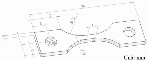
Vickers hardness (Hv, HM-5, China) of the three alloys was measured by a hardness instrument (dwell time: 10 s and load: 300 g), an average value of 10 measurements were reported as the hardness of the alloys. The tensile test of specimens was measured with the deformation rate of 0.5 mm/min. The geometry of the tensile specimen used in the work is shown in . The density of the alloys was measured based on the Archimedes’ principle. The microstructure, elemental distribution maps and wear morphologies of testing specimens were analyzed by a scanning electron microscopy (SEM, IT-300, Jeol, Japan), transmission electron microscopy (TEM, JEM-1200EX, Jeol, Japan) and energy dispersive spectroscopy (EDS, X-MAX-50, Oxford, Instruments, UK). TEM samples were prepared by wire electrical discharge machining, under cooling, and subsequently ion milling. The phases of the three alloys were examined by X-ray diffraction (XRD, DIFFRACTOMETER-6000, Shimadzu, Japan), and the lattice parameters were estimated from the XRD patterns. The content of different phases was quantitatively analyzed with Rietveld method by using the Jade 6.5 software. After wear tests, a surface profilometer was used to test the cross-sectional profile of the wear tracks in order to calculate the wear volume at different testing conditions. The wear rates of alloys were calculated using W = V/F·L where V is the wear volume (mm3), F is the normal load (N), and L is the wear sliding distance (m).
Figure 1. The schematic of tensile specimen
3. Results and discussion
3.1. Material features
shows XRD patterns of the synthesized alloys. The existing phases include ε(hcp) and γ(fcc) of two allotropes of cobalt [Citation9,Citation16], and they are the same for all the alloys. At elevated temperatures, during sintering, alloying elements dissolve into the cobalt crystal cell and form γ(fcc) solid solution [Citation4,Citation9]. When the sintering temperature decreases, the high-temperature stable γ(fcc) phase transforms partly into ε(hcp) with low-temperature stability during cooling. However, the differences in the position of γ(fcc) and ε(hcp) peaks can be observed in the figure. The atomic radii of W and Mo are 137 and 139 pm, respectively, larger than the atomic radius of Ni (125 pm). When W and Mo dissolve into Co crystal cells, the increase of dimensions for W and Mo is big as compared to Ni (see ). The peaks of γ(fcc) and ε(hcp) for CW and CMo move to the low angle in comparison with those of CNi according to the relative unit cell size. CMo and CNi alloys show the highest and the lowest relative peak intensities for the ε (hcp), respectively. The opposite trend is observed for the γ (fcc) phase. Ni favors the stability of γ (fcc), while Mo favors the stability of ε (hcp) [Citation10,Citation17]. The TEM micrographs in –) compare the dislocation content in the three alloys. Here dislocations appear as black lines whose total length per unit area is regarded as dislocation density. It can be seen that dislocation density increases with the addition of Ni, W, and Mo. Bearing in mind that these micrographs show the materials in the undeformed condition, the increase in dislocation density from CNi to CW to CMo can be explained by the increase in atomic radii mismatch with the same order. The selected area electron diffraction (SAED) patterns, shown as insets in , are gathered from the circled areas and display the typical γ(fcc) structure in all the three cases. The γ(fcc) phase does not completely transform into ε(hcp), whose presence decreases the strength of the alloys.
Table 2. Lattice parameters and different phases content in the studied alloys
Figure 2. XRD patterns of three alloys
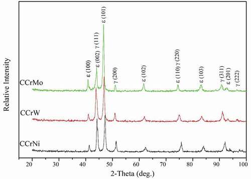
Figure 3. Bright field TEM images of dislocation and SAED patterns of alloys: (a) CNi, (b) CW and (c) CMo
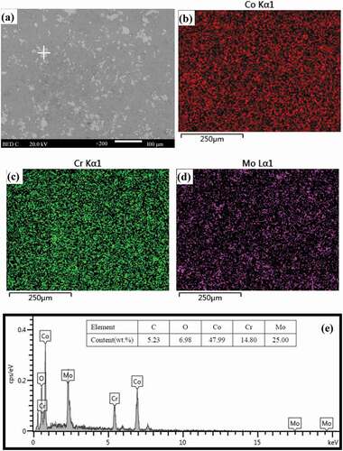
Microstructures and EDS elemental maps of three alloys are shown in –. All specimens are relatively dense, although small holes are noted on the surfaces of alloys. However, the three alloys show significant microstructural differences due to the addition of different alloying elements. It is clear that Co and Cr elements are both continuously distributed as the matrix material for all the three alloys. Ni-rich solid solution phase forms network structure in CNi, embedded in the matrix (see )). The network-like Ni-rich solid solution phase acts as a reinforcement and strengthens the alloys. For the CW and CMo specimens, the grey area is the matrix phase. The bright grey area is the W-rich and Mo-rich solid solution strengthening phases (see ) and )).
Figure 4. Backscattered electron image and elements distribution of CNi
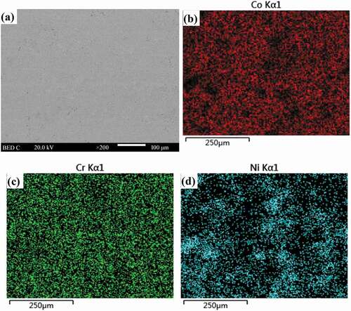
Figure 5. Backscattered electron image, elements distribution and EDS analysis of CW
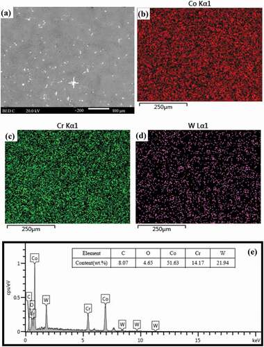
Figure 6. Backscattered electron image, elements distribution and EDS analysis of CMo
gives the mechanical and physical properties of cobalt matrix alloys. The ε(hcp) phase has the brittle and hard properties [Citation18]. However, the γ(fcc) phase has a good toughness compared with ε(hcp) [Citation11]. The CW and CMo have higher content of ε(hcp) than CNi (see ). And therefore, the Vickers hardness and tensile strength of CW and CMo are higher than those of CNi. The atomic concentration of Mo is more than that of W in order that the ε(hcp) content is high in specimen CMo. So specimen CMo shows a high Vickers hardness. The brittleness of alloys increases and the ductility decreases with the increase of ε (hcp) phases. CNi shows an elongation of over 30%, indicating high ductility. However, CMo and CW show a very high rate of strain hardening, showing very little ductility (see ). The brittle hard ε(hcp) phase could act as obstacles for ductility of Co matrix alloys. Hence, the CMo shows the lowest elongation in comparison with those of other alloys. Porosity of three alloys is low, which is in agreement with the microstructure of specimens (see –). The difference of alloying elements also results in the difference of density of alloys.
Table 3. Mechanical and physical properties of three alloys
Figure 7. The stress–strain curves of three alloys
3.2. High-temperature friction and wear performance
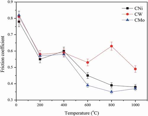
The variations of the friction coefficients of three alloys sliding against Si3N4 ceramic ball from room temperature to 1000 °C at 10 N and 0.29 m/s are shown in . The coefficient of friction of testing alloys reduces with the increase in temperatures. CNi, CW and CMo alloys show the comparable friction coefficients at the temperatures below 400 °C with CNi showing slightly lower friction of coefficients compared to CW and CMo. However, the significant differences in the friction coefficients of CNi, CW and CMo can be observed for temperature above 600 °C. The friction coefficient of CW initially increases, followed by a subsequent decrease. The CW keeps the highest friction coefficient, while CMo shows the lowest coefficient of friction from 600 °C to 1000 °C. The mechanism will be discussed below.
Figure 8. Friction coefficients of specimens vs. temperature at 0.29 m/s and 10 N
The specific wear rates of CNi, CW and CMo alloys with temperature at 10 N and 0.29 m/s are given in . The trend of wear rates is different from that of coefficients of friction during sliding. The wear rates of alloys have a similar fluctuation from 23 °C to 1000 °C. As the temperature increases, the wear rates first increase up to 600 °C after which the wear rates begin to decrease. At 600 °C, all testing specimens show the maximum wear rate, and the wear rate is about one or two order of magnitude higher than those of other testing temperature points. In the explored temperature range, CMo shows the excellent wear resistance from room temperature to 1000 °C. According to the results, wear rates of CMo are on the order of 10−6 mm3/m.N at room temperature, 800 °C and 1000 °C. The wear rates for CW are close but higher than those for CMo. The CMo shows good wear resistance at low temperature and high temperature.
Figure 9. Wear rates of specimens vs. temperature at 0.29 m/s and 10 N
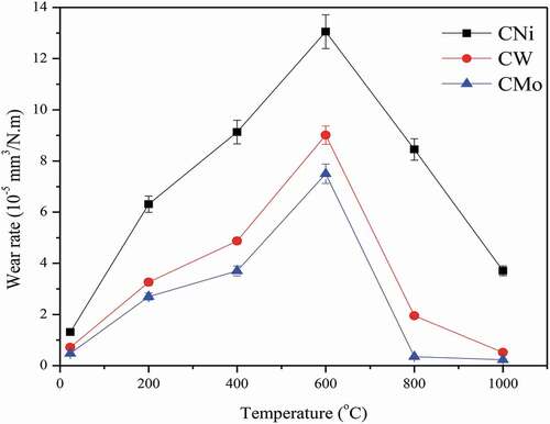
The coefficients of friction are not correlated with the wear rates of three alloys reinforced with different alloying elements. At low temperatures, the alloys possess high resistance to plastic deformation and fracture as well as high hardness, which in turn result in higher resistance against materials removal during sliding. As a result, the coefficients of friction of the three alloys are higher at low temperatures. Especially, the hardness of materials is a common quantization parameter to determine the wear resistance of materials at different testing conditions [Citation19,Citation20]. With an increase in temperature, the materials become softer in order that the sliding resistance and wear resistance of specimens decrease. Oxidation behavior is another factor that can influence the friction and wear behaviors [Citation4,Citation13,Citation14]. Oxides can form a continuous and stable film (glaze layer) on the wear scars for most materials. In this experiment, at 600 °C, the oxide film is not found on the worn surfaces (see )). However, the wear scar is covered by a continuous and stable oxide film at 800 °C (see )). Below 600 °C, the materials on the contact surfaces undergo an oxidation–oxide removal cyclic process, adding to the wear rate of materials. Meanwhile, ε(hcp) transfers into γ(fcc) when the temperature exceeds phase transition point, resulting in the decrease of hardness of alloys [Citation21,Citation22]. The above two points should be responsible for the high wear rates of the alloys at 600 °C. Above 800 °C, the accumulation rate of oxides increases (see ), and the stable oxide film forms. This film can provide lubricating effect for materials [Citation4,Citation13], which can protect surface material from oxidation. As a result, oxidation–oxide removal cyclic process greatly slows down. Consequently, at higher temperatures, alloys show low coefficients of friction and wear rates. From the hardness viewpoint, CNi has the highest wear rates in comparison with those of other specimens, and CMo shows the lowest wear rates from room temperature to 1000 °C. Additionally, W-rich and Mo-rich phases in matrix can sustain large load during sliding. This factor may be a positive contribution to the wear resistance of the alloys at elevated temperatures. At higher temperature, the large amount of Cr2WO6, WO3 and CoWO4 form on the wear tracks of CW (see )). With the hard and brittle nature of these compounds, the oxide film containing Cr2WO6, WO3 and CoWO4 can more easily fracture and form wear debris which can act as the third body during sliding [Citation23]. When the fractured oxides slide between contacting surfaces, they can increase the coefficients of friction of CW at elevated temperatures. For CMo, Mo in situ forms CrMoO4, CrMoO3 and CoCr2O4 compounds (see )), which can act as high-temperature solid lubricants during the friction process [Citation24,Citation25]. Generally speaking, CMo reinforced by Mo is found to show the best friction and wear behaviors from room temperature to 1000 °C. It does conclude that the alloying elements play an important part in the high-temperature tribological properties of alloys from room temperature to 1000 °C.
Figure 10. Cross section of wear tracks of CMo at (a) 600 °C and (b) 800 °C
Figure 11. XRD patterns of worn surfaces of three alloys tested at 1000 °C: (a) CNi, (b) CW and (c) CMo
3.3. Worn surfaces analysis
illustrates the worn surfaces of different alloys sliding against Si3N4 ball at room temperature. Obvious grooves, plastic deformation and wear debris are noted on the wear tracks. Asperities on the contact surfaces cut the surfaces and cause grooves as well as deformation. Subsequently, the ploughed material forms wear debris on the surfaces. With the increase of hardness and brittle of alloys, the resistance of mechanical attack and adhesion of alloys is reinforced during sliding [Citation10]. It is difficult for the asperities and wear debris to plough the worn surfaces. And therefore, the characteristics of debris, plastic deformation and grooves gradually weaken at room temperature. It suggests that the wear mechanism of CNi, CW and CMo is plastic deformation and abrasive wear at room temperature. SEM images of worn surfaces of the alloys at 600 °C are given in . Surfaces of wear tracks become coarser compared to those at room temperature. Because of phase transformations and decrease in hardness, the extent of plastic deformation and the depth of grooves increase at 600 °C for CNi and CW alloys. This observation is directly related to the higher wear rates measured at 600 °C. Meanwhile, less oxide film starts to form on the worn surfaces. Thus, the wear mechanism of CNi and CW is mainly severe plastic deformation an abrasive wear. However, CMo shows slight abrasive wear characteristics.
Figure 12. SEM images of worn morphologies of the three alloys tested at room temperature: (a) CNi, (b) CW and (c) CMo
Figure 13. SEM images of worn morphologies of the three alloys tested at 600 °C: (a) CNi, (b) CW and (c) CMo
illustrates SEM images of wear tracks of CNi, CW and CMo at 1000 °C. It can be observed that the surfaces of wear tracks of the alloys are covered by an oxide film. The materials and wear debris are easily oxidized, which are compacted to form a stable oxide film on the contact surfaces at 1000 °C. Oxide film separates the alloys and the ceramic ball during friction process, and provides lubricating effect for the alloys at elevated temperatures [Citation11,Citation14,Citation25]. Additionally, the stable oxide film can act as a protective film to prevent fresh material from exposing on the contact surfaces in order to avoid the further oxidation and wear of materials during sliding. It is noted that CW oxide film does not fully cover the worn surface (see )). There is some broken area. This phenomenon is attributed to the brittle nature of Cr2WO6, WO3 and CoWO4. The pristine metallic surfaces, after oxide fracture, are re-oxidized which lead to the high wear rates at elevated temperatures, and the wear debris increase the coefficient of friction. Based on the above observations, oxidative wear is the main wear mechanism of CNi, CW and CMo at 1000 °C.
Figure 14. SEM images of worn morphologies of the three alloys tested at 1000 °C: (a) CNi, (b) CW and (c) CMo
and give the wear scars of ceramic balls sliding against CNi, CW and CMo at room temperature and 1000 °C. The transferred material is rarely noted on the surfaces of wear scars for all testing specimens at room temperature (see ). It indicates that the friction model is the mutual-friction between specimen and ceramic ball. So the friction coefficients of all alloys are very high and the tribocouples suffer from wear at room temperature. At 1000 °C, the continuous transferred layer is found on the wear surfaces of CNi and CMo (see )). According to EDS analysis (see )), the transferred material mainly contained oxides. The presence of transferred layer on the surfaces changes the sliding friction pattern, namely, the friction becomes the internal friction between oxide film and transferred layer with lubricating effect. Due to the brittleness of Cr2WO6, WO3 and CoWO4, the adhesion is poor. It is hard to form a stable and continuous transferred layer on the tribocouple of CW (see )), which leads to the high friction coefficient and wear rate at elevated temperatures.
Figure 15. Worn scars observed after sliding ceramic balls against different alloys tested at room temperature: (a) CNi, (b) CW and (c) CMo
Figure 16. Worn scars observed after sliding ceramic balls against different alloys at 1000 °C: (a) CNi, (b) CW, (c) CMo and (d) EDS analysis of transferred layer of CMo
4. Conclusions
CoCrNi, CoCrW and CoCrMo were prepared by P/M, which belonged to duplex alloy, including γ(fcc) and ε(hcp). The ε(hcp) phase content of CM is higher than that of CN. Nickel stabilized the γ(fcc). However, W and Mo could stabilize ε(hcp) phase. CM showed the highest Vickers hardness and the density of dislocation.
Friction and wear behaviors of CoCr matrix alloys depended on the hardness, microstructure, phases, alloying elements and temperature. The Ni-rich phase, W-rich and Mo-rich solid solutions could sustain external load. Cr2WO6, WO3 and CoWO4 had the hard and brittle nature. During sliding, these compounds could more easily fracture and formed wear debris which acted as the third body, and the wear debris destroyed the tribological properties of alloys. In situ formed CrMoO4, CrMoO3 and CoCr2O4 provided lubricating effect for CMo as high-temperature solid lubricants at elevated temperatures. At low temperature, the wear resistance of the three alloys depended on the hardness.
CoCr matrix reinforced with Mo showed the best wear and friction behaviors from room temperature to 1000 °C. It attributed to the high hardness, intact oxide film, Mo-rich phase and chromates as well as molybdates as solid lubricants.
The dominant wear mechanism of CNi, CW and CMo was plastic deformation and abrasive wear at low temperature. The three alloys showed the characteristics of oxidative wear at elevated temperatures.
Disclosure statement
No potential conflict of interest was reported by the authors.
Additional information
Funding
References
- Lou M, Alpas AT. High temperature wear mechanisms in thermally oxidized titanium alloys for engine valve applications. Wear. 2019;426–427:443–453.
- Ming HL, Liu XC, Lai J, et al. Fretting wear between Alloy 690 and 405 stainless steel in high temperature pressurized water with different normal force and displacement. J Nucl Mater. 2020;529:151930.
- Zaman HA, Sharif S, Kim DW, et al. Machinability of Cobalt-based and Cobalt Chromium Molybdenum Alloys-A Review. Procedia Manuf. 2017;11:563–570.
- Scharf TW, Prasad SV, Kotula PG, et al. Elevated temperature tribology of cobalt and tantalum-based alloys. Wear. 2015;330-331:199–208.
- Shah TD, Naveen YG, Kattimani P, et al. Stress distribution & deflection in an Aramany class II obturator fabricated with cobalt-chromium & titanium alloys–3D FEA. Saudi Dent J. 2019;31:251–257.
- Dilawary SAA, Motallebzadeh A, Afzal M, et al. Laser surface melting of 10 wt% Mo alloyed hardfacing Stellite 12 plasma transferred arc deposits: structural evolution and high temperature wear performance. Opt Laser Technol. 2018;101:404–412.
- Hassani FZ, Ketabchi M, Bruschi S, et al. Effects of carbide precipitation on the microstructural and tribological properties of Co–Cr–Mo–C medical implants after thermal treatment. J Mater Sci. 2016;51:4495–4508.
- Joseph J, Haghdadi N, Shamlaye K, et al. The sliding wear behaviour of CoCrFeMnNi and AlxCoCrFeNi high entropy alloys at elevated temperatures. Wear. 2019;428-429:32–44.
- Kapoor S. High-temperature hardness and wear resistance of stellite alloys. Carleton University; 2012.
- Liu R, Yao JH, Zhang QL, et al. Sliding wear and solid-particle erosion resistance of a novel high-tungsten Stellite alloy. Wear. 2015;322-323:41–50.
- Luo JS, Wu SQ, Lu YJ, et al. The effect of 3 wt.% Cu addition on the microstructure, tribological property and corrosion resistance of CoCrW alloys fabricated by selective laser melting. J Mater Sci Mater Med. 2018;29: 37.
- Birol Y. Thermal fatigue testing of Stellite 6-coated hot work tool steel. Tribol Int. 2010;43: 2222–2230.
- Radu I, Li DY. A further study of the beneficial effects of yttrium on oxide scale properties and high-temperature wear of stellite 21. Tribol Lett. 2008;30: 27–34.
- Radu I, Li DY. The wear performance of yttrium-modified Stellite 712 at elevated temperatures. Tribol Int. 2007;40: 254–265.
- Rodríguez-Castro GA, Reséndiz-Calderon CD, Jiménez-Tinoco LF, et al. Micro-abrasive wear resistance of CoB/Co2B coatings formed in CoCrMo alloy. Surf Coat Technol. 2015;284:258–263.
- Zhang EL, Ge Y, Qin GW. Hot deformation behavior of an antibacterial Co–29Cr–6Mo–1.8Cu alloy and its effect on mechanical property and corrosion resistance. J Mater Sci Technol. 2018;34:523–533.
- Cabrol E, Boher C, Vidal V, et al. A correlation between tribological behavior and crystal structure of cobalt-based hardfacings. Wear. 2019;426-427:996–1007.
- ASM Handbook Committee. Nickel, cobalt, and their alloys. (USA): ASM International; 2000.
- Wang L, Yang J, Bi QL, et al. The tribological properties of a nano-eutectic Fe1.87C0.13 alloy under liquid paraffine lubrication. Tribol Lett. 2010;37: 183–189.
- Cui GJ, Bi QL, Niu MY, et al. The tribological properties of bronze–SiC–graphite composites under sea water condition. Tribol Int. 2013;60: 25–35.
- Chen Y, Tang YC, Zhang HA, et al. Microstructures and hardness prediction of an ultrafine-grained Al-2024 alloy. Metals. 2019;9:1182.
- Saldívar-García A, Lopez H. Microstructural effects on the wear resistance of wrought and as-cast Co-Cr-Mo-C implant alloys. J Biomed Mater Res A. 2005;74:269–274.
- Wu YM, Zhao J, Chen XM, et al. Effect of high temperature and oxidation on microstructure and properties of WC-10Co4Cr coatings. Chin J Nonferrous Met. 2017;27:1395–1402.
- Cui GJ, Han JR, Wu GX. High-temperature wear behavior of self-lubricating Co matrix alloys prepared by P/M. Wear. 2016;346-347:116–123.
- Kong LQ, Zhu SY, Qiao ZH, et al. Effect of Mo and Ag on the friction and wear behavior of ZrO2(Y2O3)–Ag–CaF2–Mo composites from 20 °C to 1000 °C. Tribol Int. 2014;78: 7–13.