
 ?Mathematical formulae have been encoded as MathML and are displayed in this HTML version using MathJax in order to improve their display. Uncheck the box to turn MathJax off. This feature requires Javascript. Click on a formula to zoom.
ABSTRACT
The anaerobic corrosion of steel was monitored under simulated Swiss low-/intermediate-level waste repository conditions. Steel was studied both as bare rods and cast in cement, in water vapour, simulating the unsaturated anoxic phase, and during immersion in various pore waters, representative of the saturated phase. All tests were performed at 50°C. Hydrogen evolution from grout, comprising commercial cement and sand, was also studied. Grouted steel specimens initially generated hydrogen that was comparable to grout alone, which was attributed to the presence of iron detritus from the ball-milling of cement clinker. The corrosion rate of immersed test specimens peaked during the first 100 days, likely due to the formation of a passive film. Corrosion rates generally declined to <3 nm/year, although there were several notable exceptions where hydrogen generation was erratic. This was attributed to localised corrosion and may be an important factor to understand when modelling hydrogen generation rates.
This paper is part of a supplement on the 6th International Workshop on Long-Term Prediction of Corrosion Damage in Nuclear Waste Systems.
Introduction
The Swiss waste management programme foresees that low- and intermediate-level radioactive waste (L/ILW) will be disposed of in a deep geological repository constructed in Opalinus Clay. The waste will be emplaced in caverns with a cross-section of approximately 11 m × 13 m and a length of 200 m. After emplacement of the waste, the caverns will be backfilled with cementitious mortar and sealed with concrete plugs. After closure of the repository, the available oxygen will be consumed by a number of processes such as metal corrosion, microbial activity, reactions with organic matter, oxidation of minerals or other mechanisms. Once the oxygen is consumed, anoxic conditions will prevail in the L/ILW caverns and are expected to remain indefinitely. The evolution of the near-field will be mainly controlled by the resaturation of the backfilled emplacement caverns and the physico-chemical interactions of the inflowing pore water with the cementitious backfill and the waste materials. Gas production in the repository, due to the decomposition of organic materials and the anoxic corrosion of metals, will slow down the resaturation of the emplacement caverns over thousands of years [Citation1]. The generation of gas is a safety-relevant process which can influence the long-term behaviour of a L/ILW repository and can lead to the build-up of pressure and to the displacement of pore water into the host rock or along the backfilled repository structures.
From a total of 7.72 × 10⁷ kg of waste to be disposed of in the L/ILW repository, 5.07 × 10⁷ kg comprises metallic materials. The L/ILW metal inventory consists of 84% iron and carbon steel, 10% stainless steel, 4% lead and 2% other metals. Thus, the corrosion of iron and carbon steel is the dominant source of gas in the repository. Under anaerobic conditions, the corrosion of iron proceeds through the following reaction:(1)
(1) Ferrous hydroxide may transform via the Schikorr reaction into magnetite, releasing more hydrogen:
(2)
(2) Thus the overall corrosion reaction then is
(3)
(3) The anaerobic corrosion of steel in conditions representative of L/ILW disposal has been studied mainly in alkaline electrolytes, aiming to simulate cement pore water using a variety of electrochemical, gravimetric or gas measurement techniques. These results are summarised in a comprehensive review [Citation2]. Fewer studies on steel embedded in deaerated cement exist in the literature. The available long-term anaerobic corrosion rates for steel in cement measured by hydrogen generation are shown in .
Table 1. Experimental conditions and results of published corrosion studies on carbon steel embedded in cement under anaerobic conditions. The corrosion rate was determined by hydrogen generation in all references.
The long-term corrosion rate of steel needs to be better quantified and the relevant reaction mechanisms understood in order to accurately model the evolution of the repository pressure which can influence the displacement of pore water and repository resaturation.
Experimental
Three types of test specimen were studied: backfill grout, bare steel rods and steel rods encased in backfill grout.
Backfill grout
The grouts used in the present study were intended to replicate the grouts that will be used to backfill the repository emplacement caverns. The high porosity permits the accumulation and storage of hydrogen, generated through corrosion. The grout composition is detailed in . Three cements were used in the present study: Holcim T-50 high sulphate-resistant cement was used for the majority of test specimens; Lafarge high sulphate-resistant cement was used for a limited number of comparative tests; and for experiments requiring hand-ground cement, Holcim conventional Portland cement (Type IV clinker) was used, with 3.5% (by weight) gypsum (Fisher Scientific) added.
Table 2. Backfill grout composition.
Sand (Best Sand Corporation) was sieved to remove particles smaller than 600 µm, but not otherwise altered. Grains had an average size of 2.8 mm, with a standard deviation of 0.6 mm.
Dry components were manually mixed for 90 s before the addition of tap water and subsequent mixing for 120 s. Grout preparation was conducted in air, and the mixture loaded into a cylindrical PTFE-lined mould 42 mm in diameter, producing a specimen of 86 mm in height. The specimen was then transferred to an anaerobic glove box and into the head space of a sealed glass jar containing deoxygenated deionised water. The specimen was left to cure for 5–6 days in this 100% relative humidity environment before being transferred to the test cell.
The intended fresh grout density was 1917 kg m−3, with a pore volume in excess of 25%. The average mass of a grout specimen was 234 g.
Steel
The steel rods were of nominal 3.2 mm diameter, supplied in the as-drawn condition by Goodfellow Cambridge Limited (Catalogue number FE007920). Rods had a nominal composition (major components only) of 0.2% C, 0.94% Mn, 0.31% Si, 1000 ppm Cu, 300 ppm Cr, 200 ppm Cr, Ni and Mo, 100 ppm Al and 50 ppm Co and Sn, balance Fe.
The steel rods were hand-abraded with #180 emery paper, then cut to lengths of 80 mm and the ends sanded. Thirty two cut pieces were used in each grout specimen, averaging 156 g with a total steel surface area of 0.025 m2. The cut pieces were degreased in acetone ultrasonically for 30 min, and subsequently rinsed thoroughly with tap water and subjected to a minimum of three ultrasonic rinses in deionised water, each lasting in excess of 3 min. This resulted in limited superficial corrosion. Rods were then immersed in anhydrous ethanol, dried with flowing air and stored in a desiccator prior to use. Rods were spatially separated using two drilled PTFE discs to create a bundle of parallel rods, i.e. rods were not allowed to touch.
Grouted steel
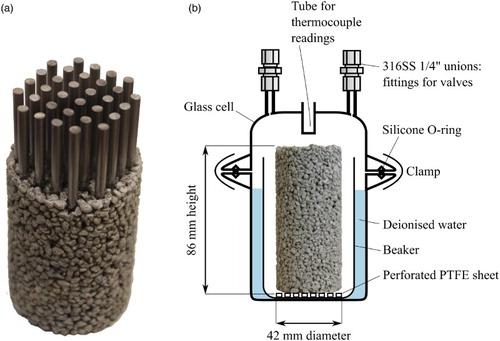
Specimens were prepared using the same quantity of steel as the steel-only experiments, and encased in grout such that the test specimen had identical dimensions to the backfill grout specimens ((a)). The average weight of backfill grout required per specimen was ∼180 g.
Figure 1. (a) Partially constructed grouted steel specimen. (b) Cell design for vapour phase tests.
Test environments
A number of electrolytes were used for vapour and immersion testing. All chemicals used were of reagent grade and prepared using 18.2 MΩ cm deionised (DI) water. All tests were conducted at 50°C.
Artificial rock pore water (ARPW) was representative of the ground water found in the Opalinus Clay at a potential Swiss repository site (based on [Citation6]). The composition is detailed in , and the water had a salinity of 12.6 g L−1 and an initial pH of ∼7.5. For electrolytes containing additional calcium or sodium hydroxide, the sodium bicarbonate was omitted.
Table 3. Composition of ARPW based on [Citation6]. The pH was approximately 7.5.
Cell design
Two-piece glass cells ((b)) were constructed with internal volumes ranging from 340 to 390 mL. Cell lids incorporated two glass tubes, to which Swagelok unions and valves were connected, and a blind-ended tube to permit recording of the cell interior temperature. For vapour phase tests, the specimen was positioned on a perforated PTFE disc within a glass beaker; the intention was to prevent immersion of the bottom of the specimen in any condensed water that might accumulate in the beaker. The annular space between beaker and cell was filled with deoxygenated deionised water (18.2 MΩ cm). For immersion tests, the specimen was positioned within a deoxygenated electrolyte-filled PTFE beaker. Cells were assembled in an anaerobic glove box, sealed with a silicone O-ring that had been coated with silicone vacuum grease, and subsequently directly purged with nitrogen gas (5.0, Linde Canada).
Hydrogen analysis
Cells were immersed in a water bath, at 50°C, for a period of time, typically 1–3 weeks, in order to accumulate hydrogen from the corrosion process. For analysis, cells were removed from the water bath and cooled to ambient temperature to remove the internal positive pressure. The cell valve was connected directly to an Ion Science Hydrosteel 6000 hydrogen probe, capable of detecting molecular hydrogen between 0.3 and 1000 ppm (by mole). The sensor response is linear with hydrogen concentration, but is also dependent upon flow rate; the probe incorporates a pump that draws analyte at a rate of 30 mL min−1 against ambient pressure. By drawing analyte from the sealed cell, the probe recorded a response that was a function of the hydrogen concentration and the rate at which a vacuum was formed within the cell. This, in turn, was dependent upon the gas volume of the cell, and was corrected for empirically using certified gas. The peak of the resulting data was found to correlate against initial cell hydrogen concentration, which was then used to determine the average corrosion rate. Following the hydrogen analysis, the cell was thoroughly purged with nitrogen to expel residual hydrogen.
The steel corrosion rate was calculated from the accumulated hydrogen, assuming that the corrosion was uniform; that hydrogen existed exclusively in the gas phase; and that the iron corrosion reaction followed was that described in reaction (3). The detection limit of this method is approximately 0.1 nm/year.
Results and discussion
A summary of the tests reported in this article is given in .
Table 4. Summary of experiments; all tests performed under anoxic conditions at 50°C.
Grout
Grout specimens without steel rods were all found to produce significant hydrogen (). Over the course of two months, cells containing Holcim cement (tests #1 and 2) produced hydrogen at an average of 3.2 × 10⁻¹⁰ moles/g/day. For a grouted steel specimen, were this to be attributed to steel corrosion, it would correspond with an average corrosion rate of 6 nm/year. To provide perspective on the sensitivity of the method, hydrogen production at this rate over a 60-day period would be equivalent to the anaerobic corrosion of an iron cube with a side length of 0.29 mm. A specimen made with Lafarge cement (test #3) produced considerably more hydrogen over the same time period which would be consistent with a corrosion rate of 25 nm/year, were the hydrogen to be generated through steel corrosion alone. Specimens based on Portland clinker which was manually ground with ceramic tools (tests #4 and 5) exhibited considerably less accumulated hydrogen after one week, suggesting that the majority of the observed hydrogen originated from the cement rather than the sand. This is likely to be due to steel wear particles from the ball-milling of the clinker. While tests #1–3 indicate a considerable variability in the amount of steel wear particles from different cement manufacturers, it would also be reasonable to assume variability between different production runs of the same manufacturer, depending on the clinker properties as well as the type and age of the milling balls. The remainder of the hydrogen may originate from the sand, which had not been washed or acid cleaned prior to use. For comparison, a grouted steel specimen made with manually ground cement (test #6) produced hydrogen at a similar rate to the commercial grout-only specimens. This emphasises the importance of different sources of hydrogen and the errors that can occur when attributing such low concentrations of hydrogen exclusively to the tested steel. The generation of hydrogen from grout is unlikely to have a significant effect on the repository in the long term as the iron detritus is expected to be consumed relatively early in the repository evolution due to their high surface area to volume ratio. A simple mass balance calculation demonstrates that the oxygen contained in the grout pores greatly exceeds the total amount of iron expected to be present in the backfill as wear particles. However, the presence of iron particles may have impact on the aerobic to anaerobic transition through the consumption of oxygen in the backfill grout pore spaces.
Figure 2. (a) Hydrogen production rates from grout, under anaerobic 100% relative humidity at 50°C after one week. As-received cements were commercial high sulphate-resistant cements; manually ground cement comprised conventional Portland cement clinker with added gypsum. Abbreviations: H, Holcim; L, Lafarge. (b) Hydrogen generation trends for tests #1 and 2.
Steel
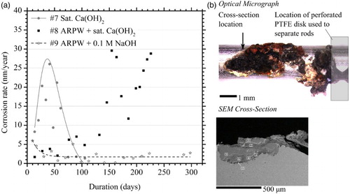
The corrosion behaviour of steel rods immersed in anaerobic electrolytes is presented in (a). The corrosion rate of rods, immersed in saturated calcium hydroxide solution, representative of partially degraded cement pore water (pH 12.5, test #7), peaked at 26 nm/year averaged corrosion rate. This subsequently reduced to sub-2 nm/year values within three months. It is hypothesised that this corrosion behaviour may be due to the formation of a passive film. Steel rods immersed in calcium hydroxide-saturated ARPW (#8) showed erratic average corrosion behaviour several months into the test. Upon dismantling the cell, a single rod was found to have undergone localised corrosion at the contact point between the rod and the PTFE spacer disc, as demonstrated in (b). The SEM image was recorded on a Hitachi S570. It was calculated that the sum of the observed hydrogen could be attributed to the corrosion of an iron cube measuring only 0.7 mm per side; this suggests that the hydrogen may be solely attributed to the localised corrosion. Steel immersed in ARPW plus 0.1 M sodium hydroxide (minus bicarbonate, test #9) rapidly passivated and corroded at a rate of less than 3 nm/year for almost a year.
Figure 3. (a) Average corrosion rate of immersed steel specimens in anaerobic electrolyte at 50°C. Abbreviations: ARPW, artificial rock pore water. (b) Optical micrograph of the single site of localised corrosion from Cell #8, and SEM micrograph of cross-section.
The initial corrosion rates described here are significantly lower than those reported by Winsley et al. [Citation7]. These authors reported corrosion rates of carbon steel wire in chloride-free ‘young cement pore water’ (pH 13.4) of approximately 2 µm/year at 25°C for in excess of 200 days, and 5–22 µm/year at 80°C for over 40 days. This may be due to the presence of an initial air-formed oxide on the steel rods used in the current work, but also the possible absorption and subsequent release of hydrogen due to the pickling, in 10% HCl solution for 5 min, of the wires used by Winsley et al. The corrosion rate in these experiments subsequently declined to the experimental detection limit, stated as 1 nm/year [Citation3], which is in agreement with the current study. Other studies support the longer-term corrosion behaviour observed in the present work: Simpson reported carbon steel anoxic corrosion rates at 50°C, over a pH range of 7–10. At pH 10, the corrosion rate was below the detection limit of 40 nm/year, and extrapolation of this trend to pH 13 strongly suggests a corrosion rate of the order 1 nm/year [Citation8]. At lower temperatures of 30 and 35°C, in saturated calcium hydroxide solutions (pH 12.4–12.8), corrosion rates of 8–20 nm/year were reported [Citation9,Citation10,Citation4].
No steel rod vapour phase tests were conducted.
Grouted steel
Grouted steel specimens were exposed to anoxic 100% relative humidity at 50°C ((a)). Specimens #10 and 11, comprising as-purchased Holcim T-50 cement, generated hydrogen at similar rates to the grout-only specimens (). Similarly, the Lafarge cement specimen (#13) produced hydrogen at a rate that was consistent with the cement alone. This rate decreased over the course of a year suggesting that the iron ball-milling detritus was nearly fully consumed or passivated by the end of the experiment. The third Holcim grouted steel specimen (#12), which was tested for a duration exceeding a year, exhibited a long-term corrosion rate in the range of 10 nm/year. Its behaviour may be attributable to localised corrosion although the specimen was not dismantled post-test to confirm this.
Figure 4. (a) Average corrosion rates of grouted steel in anoxic 100% relative humidity, at 50°C. (b) Average corrosion rates of grouted steel (commercial Holcim T-50 cement) immersed in anoxic electrolytes at 50°C.
Grouted steel specimens (Holcim T-50), immersed in anoxic electrolytes, are presented in (b). The data suggest transient corrosion behaviour for saturated calcium hydroxide electrolytes (tests #14 and 15), similar to that observed for steel rods in calcium hydroxide solution, although insufficient data were recorded to confirm passivation. The electrolyte pH at the end of the experiment was 13.00 for #14 (saturated calcium hydroxide), and 13.01 for #15 (ARPW saturated with calcium hydroxide). For grouted steel in ARPW (#16), the corrosion rate was marginally elevated to an average of 6 nm/year; the dismantled specimen revealed numerous small regions of superficial corrosion, and the final electrolyte pH was 12.90.
While the majority of the test specimens passivated, the presence of a single site of localised corrosion resulted in a <30 nm/year equivalent average corrosion rate (test #8), which had neither stabilised nor entered a phase of decline by the end of the test.
The objective of this work was to improve confidence in the long-term anoxic corrosion rate of carbon steel, which subsequently supports modelling of hydrogen generation in the repository. However, the presence of a single site of localised corrosion may result in an increase in average corrosion rate by an order of magnitude. Therefore, relying on the uniform corrosion rate to model the repository could result in an underestimate of the hydrogen generation rate if localised corrosion is actually present. Localised corrosion, under anoxic conditions, has not been reported in simulated grout fluids such as saturated calcium hydroxide. The initiation of localised corrosion may have occurred during the oxic preparation stage, and may be an artefact of the experiment itself. On the other hand, it clearly continued under anoxic conditions. Further complicating matters is the variability in water chemistry, between cement in contact with the steel surface, and the electrolyte-filled pore spaces in contact with bare steel.
It is not plausible to deduce an average corrosion rate that includes both passivity and localised corrosion from the single localised corrosion site observed in test #8. Larger scale experiments are required to better represent grouted steel, or to prove that localised corrosion is not a concern.
Conclusions
Commercial cement was found to contain considerable iron detritus. This can interfere with the calculation of grouted steel corrosion rates.
In the majority of experiments, carbon steel specimens passivated after 100 days, with corrosion rates of less than 10 nm/year.
For the single experiment that was found to have undergone localised corrosion, a significantly higher equivalent average corrosion rate was calculated, of up to 30 nm/year. This highlights the potential contribution of localised corrosion to hydrogen generation within the repository.
Disclosure statement
No potential conflict of interest was reported by the authors.
ORCID
Nick Senior http://orcid.org/0000-0001-6440-9161
References
- Diomidis N, Cloet V, Leupin OX, et al. Production, consumption and transport of gases in deep geological repositories according to the Swiss disposal concept. Nagra, Wettingen, Switzerland; 2016. (Nagra Technical Report NTB 16-03).
- Diomidis N. Scientific basis for the production of gas due to corrosion in a deep geological repository. Nagra, Wettingen, Switzerland; 2014. (Nagra Arbeitsbericht NAB 14-21).
- Smart NR, Blackwood DJ, March GP, et al. The anaerobic corrosion of carbon and stainless steels in simulated repository environments – a summary review of Nirex research. AEA Technology, Harwell, UK; 2004. (Report AEAT/ERRA-0313).
- Kaneko M, Norihiko M, Fujiwara A, et al. Evaluation of gas generation rate by metal corrosion in the reducing environment. RWMC Technical Report RWMC-TRE-03003. RWMC, Tokyo, Japan; 2004.
- Fujiwara A. Gas generation by steel corrosion under reductive conditions – continuous measurement tests. Presented at the GASNET Workshop; 2002 November 12–14; Cologne, Germany.
- Bradbury MH, Baeyens B. Far-field sorption databases for performance assessment of a high-level radioactive waste repository in an undisturbed Opalinus Clay host rock. Nagra, Wettingen, Switzerland; 2003. (Nagra Technical Report NTB 02-19).
- Winsley RJ, Smart NR, Rance AP, et al. Further studies on the effect of irradiation on the corrosion of carbon steel in alkaline media. Corros Eng Sci Techn. 2011;46:111–116. doi: 10.1179/1743278210Y.0000000010
- Simpson JP. Experiments on container materials for Swiss high-level waste disposal projects, Part-IV. Nagra Technical Report NTB 89-19. Nagra, Wettingen, Switzerland; 1989.
- Fujisawa R, Kurashige T, Inagaki Y, et al. Gas generation behavior of transuranic waste under disposal conditions. Mater Res Soc Symp Proc. 1999;556:1199–1206. doi: 10.1557/PROC-556-1199
- Nishimura T, Wada R, Fujiwara K. Evaluation of gas generation rates caused by metal corrosion under the geological repository conditions. Kobe Steel Eng Rep. 2003;53:78–83 (in Japanese).