Abstract
Neutron powder diffraction patterns of deuterated sodium cobaltate, which shows superconductivity with Tc of about 4.5 K, show conspicuous diffuse maxima presumed to originate from the deuterated sodium part in addition to sharp reflections due to the CoO2 part. The structure is treated as an interpenetration of two layered subsystem structures, the CoO2 part (a1 = 2.83 Å) and the deuterated sodium part (a2 = 3.26 Å). A model of the short-range-order stacking of the deuterated sodium part is expressed using four possible configurations. The sequences in which neighbouring sheets have the same configuration do not occur, and the other sequences occur with the same probability. Diffuse scattering intensities simulated using the matrix method satisfactorily explain the neutron diffraction patterns.
1. Introduction and experimental
Two different phases of hydrated sodium cobaltate, NaxCoO2 · yH2O (x ∼ 0.35, y ∼ 1.3), have been found to be superconductors with Tc of about 4.5 K Citation1, Citation2. The first phase was obtained from γ-Na0.7CoO2 (P63/mmc, a = 2.8 Å, c = 11.2 Å) through soft-chemical modulation, i.e. removing part of the Na by bromine and subsequent immersion in water Citation1. Most of the reflections in the X-ray powder diffraction pattern belong to a hexagonal lattice with an expanded cell constant, c, of 2 × 9.8 Å, and with two CoO2 sheets in the unit cell. The first phase can be referred to as 2H. The second phase Citation2 was obtained from α-NaCoO2 (Rm, a = 2.9 Å, c = 15.6 Å) through the same soft-chemical modulation process as that for the first phase. From rhombohedral features in the X-ray powder diffraction pattern, and with a cell constant, c, of 3 × 9.8 Å and three CoO2 sheets in its unit cell, the second phase can be referred to as the 3R phase.
Some structure models of the 2H phase were reported based on analyses of X-ray or neutron powder diffraction patterns. However, these models did not explain some important characters of the powder diffraction patterns, in particular the broad distributions of intensity around 2.8 and 2.6 Å Citation3, Citation4. In this paper, a composite crystal model of host and guest layered subsystems, the CoO2 part (a1 = b1 = 2.83 Å) and the deuterated sodium part (a2 = b2 = 3.26 Å), is proposed for both the 3R and 2H phases. Next, an interlayer short-range order model of the guest part is examined by simulation of neutron diffraction patterns of 3R and 2H of NaxCoO2 · yD2O using the matrix method for stacking faults Citation5–7.
The NaxCoO2 · yD2O (x ∼ 0.35, y ∼ 1.3) powder specimens were prepared from γ-Na0.7CoO2 (2H) or α-NaCoO2 (3R) through soft-chemical modulation with oxidation in acetonitrile solution of Br2 and immersion in D2O Citation1, Citation2. The neutron powder diffraction data were collected using the high-resolution powder diffractometer, for 3R at E9 of the Berlin Neutron Scattering Centre in the Hahn-Meithner-Institut with wave length λ = 1.797 Å and for 2H at HANARO of the Korea Atomic Energy Research Institute with wavelength λ = 1.8346 Å.
2. Structure model
In both of the neutron diffraction patterns, conspicuous diffuse scattering around 2.8, 2.6 and 1.63 Å was observed. Shapes of diffuse scattering look much alike in the patterns of 3R and 2H, and diffuse maxima in both patterns could be indexed based on a trigonal cell with dimensions (2/√3)a × (2/√3)a × c2H. We consider the diffuse scattering to originate from the guest parts, and the guest parts are assumed to be stacked in the same manner in 3R and 2H in spite of the different lattices of the host parts. The structures are treated as an interpenetration of two layered subsystem structures, the CoO2 part (a1 = b1 = 2.83 Å) with regular 3R or 2H stacking and the deuterated sodium part (a2 = b2 = (2/√3)a1 = 3.26 Å) with short-range-order stacking.
3. Simulation of diffuse scattering intensities
3.1. Fundamental composite crystal model
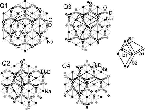
Based on the trigonal cell with a2 = b2 = 3.26 Å and c = 9.8 Å, a fundamental model of the guest sheet can be proposed based on assumed local symmetry, i.e. threefold rotation axis and an inversion centre, as shown in . An interlayer short-range order model is proposed using four possible configurations, Q1, Q2, Q3 and Q4, with respective shift vectors 0, (1/2)a2, (1/2)b2 and (1/2)a2 + (1/2)b2. In the model, sequences such as Q1–Q1, in which neighbouring guest layer units are the same, do not occur, and the other sequences, such as Q1–Q2, Q1–Q3 and Q1–Q4, occur with the same probability, 1/3. The probability table is shown in . The t-th numerical value in the s-th line is the continuing probability of the t-th layer unit after the s-th layer unit. In the matrix method for simulation of scattering from stacking disorder Citation5–7, the matrix P, whose element Pst is identical to the t-th value in the s-th line of , is used with the matrixes V and F, whose elements are given by (V)st = VsVt, (F)ss = ws, (F)st = 0 (for s ≠ t); Vs is the layer form factor of the s-th layer unit and ws is the existence probability of the s-th layer unit. The shift along c, c = 9.8 Å, is set to 1.0.
Figure 1. Possible configurations of fundamental structure model of the guest sheet, based on a cell a2 = b2 = 3.26 Å, c = 9.8 Å. The cell is based on the axes a2 = (2/3)a1 + (4/3)b1, b2 = −(4/3)a1–(2/3)b1 and c = c2H/2 = c3R/3, whereas the basic axes a1 and b1 are used for the CoO2 host layer. Assumed local symmetry operations in a layer unit are threefold rotation axis and inversion centre. Layer unit is illustrated using circles with dark rims for a half part (0.0 ≤ z < 0.5) and with light rims for the other half part (−0.5 ≤ z < 0.0). Occupancies of Na, O and D are estimated as 0.47, 0.89 and 0.61, respectively. Four configurations, Q1, Q2, Q3 and Q4, with respective shift vectors 0, (1/2)a2, (1/2)b2 and (1/2)a2 + (1/2)b2, are considered.

Table 1. Probability table (P) for an interlayer short-range order model.
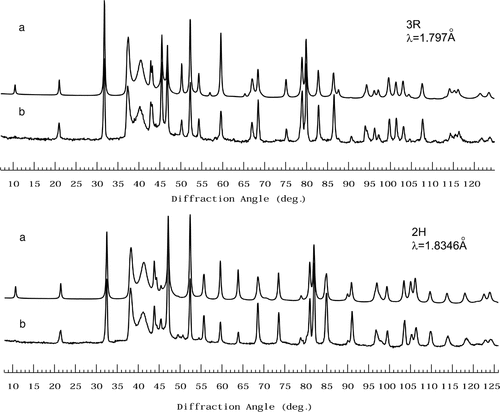
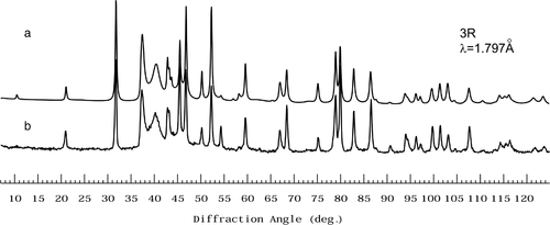
Using the computer program FU Citation8, Citation9, the intensity distribution can be calculated as a function of h2, k2 and ζ. Conventionally, the program PPROFL Citation10 can be used with FU1 for the purpose of powder pattern simulation Citation11. In this work, a part of the procedure for using PPROFL has been modified in consideration of the misfit between two-dimensional lattices and difference of unit cell volume of the subsystems. For 00l reflection calculation, z coordinates of all atoms in both of CoO2 part and the guest part are used. For h1k1l reflections, h1 ≠ 0 and/or k1 ≠ 0, based on a1 = b1 = 2.83 Å and 3c or 2c, coordinates of atoms in the CoO2 part are used. For h2k2ζ scattering, h2 ≠ 0 and/or k2 ≠ 0, coordinates of Na, O and D in the guest part are used. Occupancies of Na and O in the guest part were fixed to 0.47 and 0.89 based on chemical analysis, and occupancy of D was refined to be 0.61 as a variable parameter. The simulated and observed patterns for the 3R and 2H phases are shown in . Agreements are fairly good; Rp = 5.88% for 3R and Rp = 6.36% for 2H. However, the positions of the D atoms are not well refined in the present fundamental model, because O atoms are on threefold axes, as shown in , and three D atoms are bonded to an O atom.
3.2. Intralayer ordering in the guest part
The actual model of the guest part including the D2O molecules can be described on a two-dimensional superlattice with dimensions A = B = √3a2 = 2a1. Local symmetry, i.e. a threefold rotation axis and an inversion centre, is assumed on the superlattice. Depending on the position of symmetry operation, several models are considered. Using the same method described in the previous section, powder patterns of the 3R and 2H phases are simulated on the model of interpenetration of the CoO2 part and the intralayer ordered guest part (A = B = 5.66 Å) with short-range order stacking. After preliminary calculation using a least-square process, including penalty functions for the D–O distance and D–O–D angle, the model shown in is selected as a probable candidate, though diffuse scattering includes superposed information about all kinds of atom pairs in the disorder part and it will be no easy task to determine atom arrangement in the guest part.
3.3. Possible model of commensurate composite crystal
In a commensurate model, the structures of both parts are described based on a cell of A = B = 5.66 Å and they are stacked alternately. The first layer unit is the CoO2 part expressed in terms of A, B and c/2, and the second layer unit is the deuterated sodium layer unit illustrated in . A stack operation includes two steps: selecting a new elementary layer unit and placing it over the last-stacked layer unit after shifting the former by a specified vector. The vector defines the origin of the new layer relative to the origin of the last-stacked one. In a possible model for the 3R phase, we used the following eight stacking modes in the order:
| 1. | the second layer unit with a shift vector (1/3)A + (1/6)B + (1/2)c; | ||||
| 2. | the second unit with −(1/6)A − (1/3)B + (1/2)c; | ||||
| 3. | the second unit with −(1/6)A + (1/6)B + (1/2)c; | ||||
| 4. | the first unit with (1/2)c; | ||||
| 5. | the second unit with (1/2)A + (1/2)c; | ||||
| 6. | the second unit with (1/2)B + (1/2)c; | ||||
| 7. | the second unit with (1/2)A + (1/2)B + (1/2)c; and | ||||
| 8. | the first unit with (1/3)A + (2/3)B + (1/2)c. | ||||
4. Discussion
The main conclusion is that the structures of both the 3R and 2H phases of NaxCoO2 · yD2O (x ∼ 0.35, y ∼ 1.3), which show superconductivity, can be described as composite crystals of the host and guest layered subsystems, the CoO2 part and the deuterated sodium part. Broad distributions of intensity around 2.8, 2.6 and 1.63 Å are explained by an interlayer short-range order of the guest part. Fundamentally, the guest parts are stacked with the same manner in 3R and 2H phases in spite of the respective peculiar stacking of the host parts. In our model, octahedral coordination of O of the D2O molecules around Na was selected, because trial simulation based on trigonal prismatic coordination of D2O around Na gave insufficient agreement between calculated and observed patterns in diffuse intensity distribution. With the help of penalty functions for the D–O distance and D–O–D angle in a least-square process, a probable intralayer order model of the D2O molecules is proposed. Simulation based on a possible commensurate composite model of the 3R type was tried and fairly good agreement was obtained. Though the data from the guest part seem to be too diffuse to determine the details of atom arrangement, the structures have been appropriately characterized by adopting the composite crystal model of the host and guest layered subsystems and the short-range order stacking model of the guest part.
Acknowledgements
The authors acknowledge Dr. K. Kato for his computer programs.
References
- Takada, K, Sakurai, H, Takayama-Muromachi, E, et al., 2003. Nature 422 (2003), p. 53.
- Takada, K, Sakurai, H, Takayama-Muromachi, E, et al., 2004. Adv. Mater. 16 (2004), p. 1901.
- Jorgensen, JD, Avdeev, M, Hinks, DG, et al., 2003. Phys. Rev. B 68 (2003), p. 214517.
- Argyriou, DN, Radaelli, PG, Milne, CJ, et al., 2005. J. Phys. Condensed Matter 17 (2005), p. 3293.
- Hendrics, S, and Teller, E, 1942. J. Chem. Phys. 10 (1942), p. 147.
- Kakinoki, J, and Komura, Y, 1965. Acta Crystallogr. 19 (1965), p. 137.
- Kakinoki, J, 1967. Acta Crystallogr. 23 (1967), p. 875.
- Kato, K, 1991. (1991), personal communication.
- Kato, K, Kosuda, K, Koga, T, et al., 1990. Acta Crystallogr. C 46 (1990), p. 1587.
- Kato, K, 1998. (1998), personal communication.
- Onoda, M, Saeki, M, and Kawada, I, 1980. Acta Crystallogr. A 36 (1980), p. 952.

![Figure 3. A probable model of intralayer ordering in the guest part. Bounded projections along [00] (left) and along [110] (right). Occupancies of Na sites are assumed to be 1.0 (small solid circle) and 0.2 (hatched circle), and those of O and D are estimated as 0.89 and 0.96.](/cms/asset/d4093ba6-5ef4-4c97-9e30-1a9ff1e3a29d/tphm_a_207738_f0003.gif)
