
 ?Mathematical formulae have been encoded as MathML and are displayed in this HTML version using MathJax in order to improve their display. Uncheck the box to turn MathJax off. This feature requires Javascript. Click on a formula to zoom.
ABSTRACT
High angle annular dark field scanning transmission electron microscopy has been employed to observe precipitate structures in Al–Zn–Mg and Mg–Zn alloys. precipitate structures in Al–Zn–Mg are commonly formed by MgZn2 Penrose bricks, but also frequently observed to incorporate Mg6Zn7 elongated hexagons via two different modes. Tilings of MgZn2 and Mg6Zn7 building blocks in both
in Mg–Zn and
in Al–Zn–Mg alloys, create overall patterns which deviate from the chemical and structural configuration of solely monoclinic Mg4Zn7 or MgZn2 unit cells. Precipitate morphologies were found to be correlated to their internal sub-unit cell arrangements, especially to Mg6Zn7 elongated hexagons. Systematic or random arrangements of Mg6Zn7 elongated hexagons inside precipitates and therefore compositional and structural patterns, were found to be strongly related to the aspect ratio of the precipitates and altering of the precipitate/matrix interfaces.
GRAPHICAL ABSTRACT
Introduction
Mg and Al alloys are light-weight engineering materials which have multiple applications as key components in both the aerospace and automotive industry.
Mg–Zn alloys are one of the most commonly used Mg alloys due to their precipitation hardening response [Citation1]. The strengthening precipitates in Mg–Zn alloys are the metastable phases and
[Citation1]. Over-ageing occurs during extensive transformation of
to
[Citation2].
precipitate morphology is rod/lath-shaped parallel to [0001]Mg, while
is plate-shaped on (0001)Mg [Citation3]. Reports on the
structure are contradictory. It has been reported that
is a hexagonal Laves phase MgZn2, with a = 0.522 nm, c = 0.857 nm, space group P63/mmc and orientation relationship
,
[Citation4–6]. Other reports conclude that
has a monoclinic structure Mg4Zn7, a = 2.596 nm, b = 1.428 nm, c = 0.524 nm, γ = 102.5°, space group C2/m and orientation relationship
or
[Citation7–9]. However, recent reports indicate that domains belonging to the Mg4Zn7 monoclinic unit cell and the C14 Laves MgZn2 cells can co-exist inside
precipitate separated by defects where the stacking sequence changes [Citation10,Citation11]. HAADF-STEM characterisation in Mg–Zn alloys, suggested that precipitates nucleating on dislocations show quasicrystalline structures made of rhombic and hexagonal tiles in contrast to C14 Laves MgZn2 crystals precipitating inside undeformed Mg matrixes [Citation12]. shows four monoclinic unit cells Mg4Zn7 along [001]Mg4Zn7 and its distinctive substructures C14, C15 MgZn2 and elongated hexagon-shaped Mg6Zn7.
Figure 1. (Color online) Schematic illustration of four monoclinic conventional standard Mg4Zn7 unit cells (a = 1.315 nm, b = 1.414 nm, c = 0.528 nm, γ = 102.3°, space group C2/m) marked by the gray dashed lines along the c-axis [Citation7]. The substructure of C15 MgZn2 is marked by the red lines and C14 MgZn2 is marked by the blue lines [Citation25]. The elongated hexagon Mg6Zn7 substructure is marked by the black lines.
![Figure 1. (Color online) Schematic illustration of four monoclinic conventional standard Mg4Zn7 unit cells (a = 1.315 nm, b = 1.414 nm, c = 0.528 nm, γ = 102.3°, space group C2/m) marked by the gray dashed lines along the c-axis [Citation7]. The substructure of C15 MgZn2 is marked by the red lines and C14 MgZn2 is marked by the blue lines [Citation25]. The elongated hexagon Mg6Zn7 substructure is marked by the black lines.](/cms/asset/523aa851-606d-4333-92e2-c474942909f3/tphm_a_1637032_f0001_oc.jpg)
Zn, Mg and often Cu are added as solute elements to age hardenable 7xxx Al alloys in order to form strengthening precipitates after quenching from the solutionising temperature [Citation13]. Peak-hardened microstructures are suggested to have a homogeneous distribution of and η2 mixed with η1 particles in the Al matrix of alloys with Zn/Mg ratio over 2, which are artificially aged near the GP-zone solvus temperature [Citation14,Citation15]. X-ray investigations revealed that
is a hexagonal transition phase with approximate composition Mg4Zn11Al (Zn/Mg ∼ 3) space group
, a = 0.496 nm, c = 1.402 nm and orientation relationship
,
[Citation15]. The η phase is an equilibrium hexagonal MgZn2 Laves phase in Al alloys [Citation4,Citation5]. It exhibits 11 reported orientation relationships with the Al matrix, namely η1 to η11 [Citation16–18]. Commonly observed orientations are
and η2 which have the same orientation relationship with the Al matrix, and also η1 which forms with the following orientation relationship with Al matrix
,
[Citation18]. A combined high angle annular dark field scanning transmission electron microscopy (HAADF-STEM) and first-principles calculations study concluded that
phase incorporates structural units present in η2 – MgZn2 Laves phase and both are bounded by the {111}Al interface planes enriched with heavy solute atoms [Citation19]. The η1 internal structure was found to incorporate some different arrangements of atomic structures, deviating from the stacking of (0001) MgZn2 structure planes [Citation20]. Furthermore, a cross-section of needle-like precipitates along
Al which do not fall into any particular orientation relationship was observed to incorporate Mg6Zn7 elongated hexagons [Citation21]. Sub-unit cell of Mg6Zn7 elongated hexagons is also present in the metastable
phase [Citation21].
The present work shows results of HAADF-STEM characterisation of precipitates in Mg–Zn and Al–Zn–Mg alloy. It clarifies the internal structure of as the main strengthening precipitate in Mg–Zn alloys in relation to its cross-section morphology transformations. The same analysis extends to the structure of η1 as the second most found η phase/Al matrix orientation relationship in peak-aged Al–Zn–Mg alloys. Similarities between building structures of precipitates in both alloy systems are pointed out and discussed.
Experimental methods
Two different alloys, Mg–2.2 Zn (at. %) and Al–3.4 Zn–1.9 Mg (at. %) were prepared by melting high purity elements in a steel crucible under respectively SF6 + CO2 and Ar atmosphere. The Mg alloy was homogenised at 320°C for 12 h, hot rolled at 300°C, solution treated at 330°C for 1 h in an Ar atmosphere and quenched into iced water, followed by artificial ageing at 200°C for 480 min (8 h). The Al alloy was homogenised at 470°C for 24 h, extruded at 405°C, solution treated at 475°C for 1 h and quenched into iced water followed by 4 days natural ageing and 120°C artificial ageing for 2,000 and 10,000 min.
TEM disks were punched out from ∼60 μm thick foils and electropolished in a twin-jet polishing machine using a mixed solution of 1/3 nitric acid (HNO3) and 2/3 methanol (CH3OH) kept at a temperature between −20°C and −30°C.
A double aberration-corrected (image and probe Cs) cold-FEG Jeol ARM-200F operated at 200 kV was used for the HAADF-STEM imaging. The probe size was 0.08 nm, the convergence semi-angle was 28 mrad and the inner and outer collection angles were 35 and 150 mrad, respectively. The HAADF-STEM imaging technique provides interpretable atomic resolution Z-contrast images, where the intensity from each atomic column is nearly proportional to the square of the Z-number of the atoms composing the given atomic column [Citation22].
The high resolution HAADF-STEM images in (a) and were acquired using Smart Align, which involves acquiring a stack of successive low-dose images and afterwards aligning them to correct for rigid- and non-rigid scan distortions [Citation23].
Vickers microhardness tests were done using a dwell time of 15 s and 0.98 N load in a Mitutoyo HM-101. All hardness values were average of the ten most common indentation values.
Results and discussion
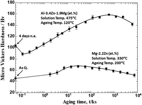
illustrates the age-hardening response of the two alloys (Al–Zn–Mg and Mg–Zn) during different ageing conditions. A peak-hardness of 158 Hv in Al–Zn–Mg alloy was reached after 10,000 min (∼7 days) ageing at 120°C after being initially natural aged for 4 days. Peak-hardness of the Mg–Zn alloy of 66 Hv was reached after 480 min (8 h) ageing at 200°C.
Figure 2. Age-hardening curves of the Al–Zn–Mg alloy during 120°C artificial ageing after initially 4 days natural ageing and the Mg–Zn alloy during 200°C artificial ageing immediately after quenching.
The microstructure of the peak-aged Al–Zn–Mg alloy has primarily precipitates observed as edge-on plates on Al,
Al and (001)Al habit planes. This is shown in , where the sample orientation along [110]Al enables edge-on views of these phases. shows an image of the Al matrix where edge-on
transition phase precipitates are indicated with white arrows, as plates 7-layer {111}Al planes thick [Citation15,Citation19,Citation24], mixed with η1 precipitates seen as edge-on plates on (001)Al planes. η1 precipitates zone axis is aligned with either
or
parallel to
. The majority of other non-indicated curved shaped precipitates are plate-like precipitates of the same crystal structure and orientation relationship as η2 and η1. The habit planes of these precipitates lie on
Al,
Al set of planes which are inclined by 54.74° from [110]Al direction (or 35.26° from (110)Al) and on (100)Al and (010)Al set of planes which are inclined by 45° from the [110]Al direction, respectively. Moreover, indicated with white arrows are precipitates corresponding probably to η4 (due to their high-aspect ratios and habit planes) or η2.
Figure 3. HAADF-STEM image along [110]Al showing microstructure of the Al–Zn–Mg alloy peak-aged at 120°C for 10,000 min (∼7 days) after 4 days natural ageing.
![Figure 3. HAADF-STEM image along [110]Al showing microstructure of the Al–Zn–Mg alloy peak-aged at 120°C for 10,000 min (∼7 days) after 4 days natural ageing.](/cms/asset/5761deb7-c683-4f77-8c90-e4cad5165bf2/tphm_a_1637032_f0003_ob.jpg)
shows a low magnification HAADF-STEM image of a region along [0001]Mg near the sample edge in the Mg–Zn sample. 97% of the observed precipitates in were identified as cross-sections of phases, in agreement with the literature, where
is referred to as lath/rod precipitates parallel to [0001]Mg [1–3,6,8–11]. In addition, only three coarse precipitates positioned near each-other were identified as
.
Figure 4. HAADF-STEM image along [0001]Mg showing microstructure of Mg–Zn alloy peak-aged at 200°C for 480 min.
![Figure 4. HAADF-STEM image along [0001]Mg showing microstructure of Mg–Zn alloy peak-aged at 200°C for 480 min.](/cms/asset/f9505675-e9e0-462b-915d-45b8e5e070df/tphm_a_1637032_f0004_ob.jpg)
(a,c) show edge-on η1 precipitates with their direction parallel to the [110]Al direction. Atomic resolution HAADF-STEM investigations clearly show the C14 stacking of the Laves structure (0001)MgZn2 planes along
. Coherency preservation every 3
and
is consistent with the coincidence of spots positions from
and
reflecting planes as shown in Fast Fourier transform (FFT) patterns in (b,d). Coarsening of precipitates is associated with incorporation of complete prolate Penrose bricks, MgZn2 (Mg2Zn4). (a,b) show incrementally increasing thickness from four to five and in length from eight to ten Mg2Zn4 Penrose bricks.
Figure 5. HAADF-STEM images of C14 MgZn2 – precipitates embedded in the Al matrix from the Al–Zn–Mg alloy aged (a) 2,000 min and (c) 10,000 min at 120°C after initially 4 days natural aged, respectively. The electron beam is parallel to
. (b) and (d) are FFT patterns of (a) and (c). Black lines connect ● spots of Al reflecting planes; + indicates some spots of MgZn2 –
reflecting planes.
![Figure 5. HAADF-STEM images of C14 MgZn2 – η1 precipitates embedded in the Al matrix from the Al–Zn–Mg alloy aged (a) 2,000 min and (c) 10,000 min at 120°C after initially 4 days natural aged, respectively. The electron beam is parallel to [110]Al∥[112¯0]MgZn2. (b) and (d) are FFT patterns of (a) and (c). Black lines connect ● spots of Al reflecting planes; + indicates some spots of MgZn2 – η1 reflecting planes.](/cms/asset/3d22098f-2b58-42ef-ab5b-20d47e0b3aba/tphm_a_1637032_f0005_ob.jpg)
shows HAADF-STEM images of cross-sections of lath-shaped precipitates observed along [0001]Mg. Atomic scale resolution investigation of lath-shaped
enables clear identification of the C14 MgZn2 Laves phase variant, build-up by (0001) plane stacking along
directions as seen in (a) and (c) – ②. However, precipitate
in (c) deviates from the solely C14 MgZn2 structure by incorporating elongated hexagonal Mg6Zn7 sub-unit cells in a chain-like pattern stretching parallel to its longer cross-section. Some Mg6Zn7 sub-unit cells are marked with blue lines. Indicated with white arrows are C15 MgZn2 stackings which are positioned at the turning points of elongated hexagon chains.
Figure 6. (Color online) HAADF-STEM images and corresponding FFT from peak-aged Mg–Zn alloy aged for 8 h at 200°C with electron beam parallel to [0001]Mg (a) C14 MgZn2 –
precipitate embedded in Mg matrix and (b) corresponding FFT pattern. (c) ① C14 MgZn2 –
incorporating Mg6Zn7 sub-unit cells in a chain-like pattern parallel to its longer cross-section length and ② C14 MgZn2 –
.
and ② are corresponding FFT patterns. Some Mg6Zn7 sub-unit cells are marked with blue hexagons. White dashed lines indicate growing fronts. Black lines connect ● spots of Mg reflecting planes, open black circles (◯) indicate spots of
reflecting planes.
![Figure 6. (Color online) HAADF-STEM images and corresponding FFT from peak-aged Mg–Zn alloy aged for 8 h at 200°C with electron beam parallel to [0001]Mg ∥[112¯0]MgZn2. (a) C14 MgZn2 – β1′ precipitate embedded in Mg matrix and (b) corresponding FFT pattern. (c) ① C14 MgZn2 – β1′ incorporating Mg6Zn7 sub-unit cells in a chain-like pattern parallel to its longer cross-section length and ② C14 MgZn2 – β1′. ① and ② are corresponding FFT patterns. Some Mg6Zn7 sub-unit cells are marked with blue hexagons. White dashed lines indicate growing fronts. Black lines connect ● spots of Mg reflecting planes, open black circles (◯) indicate spots of β1′ reflecting planes.](/cms/asset/de67508b-b0e5-4d6a-8b6a-9b92244e42b3/tphm_a_1637032_f0006_oc.jpg)
On the upper left interface of the precipitate marked as ①, in which the Mg6Zn7 chain is incorporated close-by, there are regions with higher intensity than the Mg matrix. Careful image examination reveals dim intensity contrast of MgZn2 and Mg6Zn7 tilings, compared to the intensity of the precipitate’s internal structure. It is expected that during prolonged ageing the precipitate cross-section will grow in this direction, as indicated by the white dashed line in (c) – ①. The same situation is seen in the lower right interface of the same precipitate cross-section.
(a,b) show η1 precipitates aligned with the direction parallel to [110]Al direction. Atomic scale examination reveals that a part of both precipitates exhibits structure of solely C14 MgZn2 stacking ((a)) or a combination of C15 and C14 MgZn2 stackings ((b,c)) along
. Bottom interfaces are flat, with slight deviations in case of the C15 stacking as shown by the white arrows in (b,c). The upper part of the precipitates has incorporated elongated hexagons Mg6Zn7 in a random way by combining with Penrose Mg2Zn4 building blocks as seen in (a,b). Some Mg6Zn7 sub-unit cells are marked with yellow lines. The upper η1/Al interface has gained a curved shaped interface as seen in (b). Taking the aspect ratio into consideration, η1 in (a,b) cannot be categorised as plate-shaped precipitates but more likely as sphere-shaped ones.
Figure 7. (Color online) HAADF-STEM images from the Al–Zn–Mg alloy aged for 2,000 min at 120°C after initially natural aged for 4 days, with electron beam parallel to . (a) Smart aligned HAADF-STEM image and (b) noise suppressed IFFT HAADF-STEM image of
precipitates embedded in Al matrix. (Image (c) adapted from Ref. [Citation20]). (c) Elongated hexagons Mg6Zn7 are aligned in chain-like pattern along
[0001]η. Some Mg6Zn7 sub-unit cells are marked with yellow lines.
![Figure 7. (Color online) HAADF-STEM images from the Al–Zn–Mg alloy aged for 2,000 min at 120°C after initially natural aged for 4 days, with electron beam parallel to [110]Al∥[112¯0]MgZn2. (a) Smart aligned HAADF-STEM image and (b) noise suppressed IFFT HAADF-STEM image of η1 precipitates embedded in Al matrix. (Image (c) adapted from Ref. [Citation20]). (c) Elongated hexagons Mg6Zn7 are aligned in chain-like pattern along [11¯0]Al∥ [0001]η. Some Mg6Zn7 sub-unit cells are marked with yellow lines.](/cms/asset/a5fd0e09-e444-415d-8f80-1b033156c750/tphm_a_1637032_f0007_oc.jpg)
(c)Footnote1 which is the edge-on projection of a plate-shaped precipitate on (001)Al habit plane reveals incorporation of Mg6Zn7 elongated hexagons in chain-like patterns extending along the η1 precipitate diameter. On the left and right part of precipitate shown in (c), Mg6Zn7 chain stretching form a certain angle with respect to the habit plane. This is associated with the introduction of C15 MgZn2 stacking as indicated by the white dashed arrows. White dashed lines enclose one interplanar spacing inside in which C15 stacking is observed.
(a) shows STEM images of cross-sections of lath-shaped precipitates observed along [0001]Mg. The precipitate is built up mainly by C14 MgZn2 stacking along
direction. Some Mg6Zn7 unit cells are marked with blue dashed lines. Incorporation of Mg6Zn7 elongated hexagons has occurred by aligning parallel to the longer precipitate/matrix interface as seen in (a). The chain deviating from being parallel to the longer quasi-flat interface is associated with the introduction of the C15 MgZn2 stacking. Indicated with white arrows (black dashed lines enclosing one
interplanar spacing) are C15 MgZn2 stacking.
Figure 8. (Color online) (a) and (b) HAADF-STEM image of precipitates embedded in Mg matrix in the peak-aged Mg–Zn alloy with electron beam parallel to
. (a) C14 MgZn2 –
has incorporated a Mg6Zn7 chain arrangement splitting its structure into two domains made up mainly of C14 MgZn2. (b) Domains made up of C14 and C15 MgZn2 structures are separated by chain-like arrangements of Mg6Zn7 elongated hexagons. Blue arrows indicate direction of stretching of these chains. Some Mg6Zn7 sub-unit cells are marked with blue hexagons. The white dashed line indicates the growing front.
![Figure 8. (Color online) (a) and (b) HAADF-STEM image of β1′ precipitates embedded in Mg matrix in the peak-aged Mg–Zn alloy with electron beam parallel to [0001]Mg∥[112¯0]MgZn2. (a) C14 MgZn2 – β1′ has incorporated a Mg6Zn7 chain arrangement splitting its structure into two domains made up mainly of C14 MgZn2. (b) Domains made up of C14 and C15 MgZn2 structures are separated by chain-like arrangements of Mg6Zn7 elongated hexagons. Blue arrows indicate direction of stretching of these chains. Some Mg6Zn7 sub-unit cells are marked with blue hexagons. The white dashed line indicates the growing front.](/cms/asset/93bb23f2-0a96-45db-8424-53a53848784e/tphm_a_1637032_f0008_oc.jpg)
(b) reveals a well-developed phenomenon of multiple Mg6Zn7 elongated hexagons incorporation into arrangements of resembling chains. Blue arrows indicate the alignment directions of these chains. The Mg6Zn7 chain alignments are parallel or almost parallel to the longer interface of the precipitate cross-sections. Similarly, with the previous images, chains deviate from being parallel along their entire lengths to the longer interfaces due to deviation from solely C14 MgZn2 stacking along
of the surrounding structure. The bottom interface region of the precipitate in (b) exhibits a flat interface. Meanwhile, the upper part of the precipitate in (b) is made up from a random tiling of Mg6Zn7 and MgZn2 building blocks. Their lower intensity than the precipitate internal structure, but higher intensity than that of pure Mg matrix, may indicate heterogenous nucleation on the previous
/Mg interface. Further growth of the precipitate in the direction indicated by the white dashed line in (b) may, therefore, be expected to occur with prolonged ageing treatment.
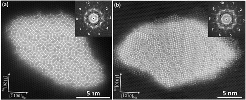
(a,b) show cross-sections of rod-shaped precipitates embedded in the Mg matrix. Low aspect ratios of precipitate cross-sections are clearly associated with the absence of flat
/Mg interfaces. Internal structures are built up by random tiling of oblate MgZn2 Penrose bricks and Mg6Zn7 elongated hexagons, generating C14, C15 MgZn2 Laves phase stackings and 5-fold symmetry atomic arrangements as seen in the FFT patterns given in the insets of (a,b). The majority of the stacking of (0001)MgZn2 planes have not occurred along any
direction. This might be related to the lack of Mg6Zn7 chain-like arrangement as obviously seen in (a) and in the left part of precipitate in (b).
Figure 9. (a) and (b) Smart aligned HAAD-STEM images of precipitates embedded in the Mg matrix in the peak-aged Mg–Zn alloy. FFT patterns are given in the insets. Black lines connect ● spots of Mg reflecting planes.
shows a schematic illustration of the tendency of sub-unit cell arrangements inside the precipitate structures of η1 and precipitates embedded in Al and Mg matrix, respectively. Successive stacking of (0001)MgZn2 planes, combined as (i) Kagome tilings of Zn atoms and (ii) mixed Zn, Mg planes lead to a variety of structures which include (C14) hexagonal MgZn2, (C15) cubic MgZn2 and (C36) MgZn2 [Citation25,Citation26]. Systematic stacking of (0001)MgZn2 occurs respectively along
or
and observations reveal that the precipitate/matrix interfaces remain sharp when precipitates are composed solely of C14 MgZn2 stacking. This case was clearly observed for precipitates in both Al and Mg matrixes as seen in and , respectively.
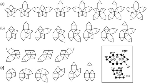
Figure 10. Illustration of (Mg2Zn4) MgZn2 Penrose bricks and Mg6Zn7 elongated hexagons sub-unit cell arrangements in a systematic configuration inside precipitates of the Al–Zn–Mg system and
precipitates of the Mg–Zn alloy system exhibiting high-aspect ratios and flat precipitate/matrix interfaces.
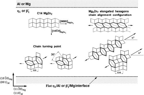
Mg6Zn7 elongated hexagon incorporation occurs (i) systematically or (ii) randomly. Incorporation of Mg6Zn7 elongated hexagons inside the precipitate structure is usually associated with the introduction of C15 MgZn2 stacking and deviation of precipitate/matrix interfaces from being completely flat.
In systematic incorporation, a tendency of alignment of Mg6Zn7 elongated hexagons in chain-like configurations occurs in precipitates which preserve flat or quasi-flat interfaces with their respective matrixes. Systematic alignment of Mg6Zn7 elongated hexagons occurs in two modes: (i) parallel or (ii) at a certain angle to the longer flat precipitate/matrix cross-section interface, as illustrated in . Moreover, Mg6Zn7 sub-unit cells rotation with 36° (with or without the participation of C15 MgZn2 stacking) enables probable chain turn from parallel to a certain angle with respect to the interface.
In random incorporation, elongated hexagons are arranged together with MgZn2 Penrose bricks in configurations that only guarantee space filling with atoms around vertexes [Citation25], probably because hexagon alignments are not restricted by interface coherency considerations in chain-like configurations. shows combinations of sub-unit cells shown in the inset, that complete a 360° space filling around a vertex. This case is typically observed in precipitates that have low aspect ratios and curved interfaces, as seen in η1 precipitates in Al matrix ((a,b)) and in rod-shaped precipitates in Mg matrix ((a,b)). Atomic scale HAADF-STEM images show that the upper part of the η1 precipitates has incorporated hexagons in a random way ((a,b)) and their upper interfaces are not as flat as the bottom ones. Once more, observations of
precipitates confirm this tendency in Mg–Zn alloy systems as clearly demonstrated in (a,b). Precipitates in which elongated hexagons are distributed randomly, do not have flat precipitate/matrix interfaces. It seems that in rod-shaped
, the only restriction of hexagon arrangements is the space filling consideration. Due to this freedom, lack of a defined unit cell, which can be extended periodically to characterise the whole precipitate, causes forbidden translation symmetry and long-range rotational symmetry. In this case, the precipitate’s structure is considered approximately quasiperiodic in the plane perpendicular to the observation axis [Citation27].
Figure 11. 360° – space filling combinations of (Mg2Zn4) MgZn2 Penrose brick and Mg6Zn7 elongated hexagons surrounding vertexes. (a) tiling of regular vertex of five edges sharing a common Zn-rich atomic column and its equivalent versions; (b) tiling of irregular vertex of four edges sharing a common Zn-rich atomic column and its equivalent versions (c) tiling of irregular vertex of three edges sharing a common Zn-rich atomic column and its equivalent version. In the inset, building blocks in which, ● Zn and ![]()
From the results obtained through HAADF-STEM characterisation of precipitates in Al–Zn–Mg and Mg–Zn, it was confirmed that precipitates are made up from arrangement of two basic building blocks, Penrose brick Mg2Zn4 and elongated hexagon-shaped Mg6Zn7. In particular, a clear trend of random elongated hexagon incorporation is observed in those precipitates which have low aspect ratio and generally curved interfaces. This case is confirmed for both alloy systems, as observed in precipitates shown in (a,b) for Mg–Zn alloys and (a,b) for Al–Zn–Mg alloys.
A total lack of elongated hexagon incorporation is observed in those precipitates which have high-aspect ratios and generally flat or quasi-flat interfaces with their respective matrixes. This is clearly observed in precipitates in Al–Zn–Mg shown in and
precipitates in Mg–Zn shown in (a) and (c) – ②. As the precipitates start to incorporate hexagons into their structures, the system probably still wants to preserve the interface coherency, which in turn constrains incorporation of Mg6Zn7 elongated hexagons. This causes them to align in chain-like configurations extending either parallel to or at an angle with respect to matrix/precipitate interface, as clearly seen in
precipitates in Al–Zn–Mg shown in (c) and
precipitates in Mg–Zn shown in and (c) – ①. The general trend of hexagon alignments in chain-like arrangements is illustrated in .
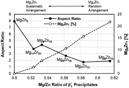
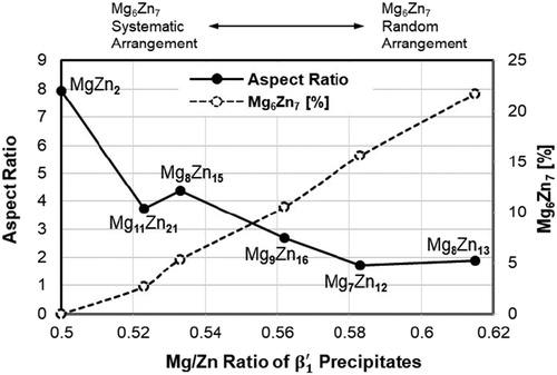
The relation between the aspect ratio (measured on precipitates cross-section projections on (0001)Mg plane) and the precipitate composition of precipitates is shown in . It is seen that the aspect ratio is negatively correlated to the Mg/Zn ratio and it is extremely sensitive to slight changes of it. Increasing the Mg/Zn ratio in the precipitates from 0.5 to around 0.6 (20%), decreases the aspect ratio from 8 to around 2 (75%). The Mg/Zn ratio increases due to the introduction of Mg6Zn7 elongated hexagons which are rich in Mg. The dashed line shows the percentage of Mg6Zn7 elongated hexagons, calculated as the ratio of a number of Mg6Zn7 hexagons over the total number of Mg6Zn7 elongated hexagons + MgZn2 Penrose bricks, which build up the precipitate structures. From all observations, it becomes obvious that there is a strong relation between precipitate morphology and its chemical composition, specifically due to Mg6Zn7 elongated hexagons. This new concept may also be used in studying precipitation behaviour of other alloy systems in order to explain internal structural changes of precipitates in relation to their morphological transformations.
Figure 12. Relationship between aspect ratio and Mg/Zn ratio of precipitate composition (respective chemical compositions of precipitates) in the Mg–Zn alloy systems is shown with a continuous black line. The dashed black line shows the incorporation percentage of Mg6Zn7 elongated hexagons calculated as the ratio of number of Mg6Zn7 hexagons over the total number of sub-unit cells building up the precipitates (Mg6Zn7 elongated hexagons + MgZn2 Penrose bricks).
The MgZn2 precipitates with the highest aspect ratios and flat interfaces are generally stacked as C14 variant, as seen in the Al–Zn–Mg alloy () and Mg–Zn alloy ( (a,c) – ②). Precipitates with slightly higher Mg/Zn ratios still preserve their coherency across their interfaces, and this may induce elongated hexagons alignment in a systematic way (chain-like configuration) as seen in Al–Zn–Mg alloys ((c)) and Mg–Zn alloys (). Higher Mg/Zn ratios are related to precipitates which possess low aspect ratios and curved interfaces and random arrangement of Mg6Zn7 hexagons as is the case for Al–Zn–Mg alloys ((a,b)) and Mg–Zn alloys ().
Conclusions
Precipitates in two alloy systems, Al–Zn–Mg and Mg–Zn alloys were investigated using HAADF-STEM making it possible to directly interpret crystal structures and interfaces. From the experimental results the following conclusions were drawn:
η1 precipitates in Al–Zn–Mg alloys, next to the previously reported MgZn2 Penrose bricks, incorporate Mg6Zn7 elongated hexagons.
Mg6Zn7 elongated hexagon arrangements inside precipitates of both alloy systems are not restricted to that of Mg4Zn7 unit cell case. These arrangements appear in two configurations:
Systematic configuration: Mg6Zn7 elongated hexagons were aligned in chain-like configurations stretching parallel or at a certain angle to the long precipitate/matrix interfaces.
Random configuration: Mg6Zn7 elongated hexagons were arranged together with MgZn2 Penrose bricks in 360°-space filling combination around vertexes.
Precipitate morphologies are strongly related to their internal sub-unit cells arrangements, especially to Mg6Zn7 elongated hexagons. The same relationship trend is observed between morphologies and internal structures, regardless of which matrices the precipitates are embedded in, Al or Mg. Aspect ratios of precipitates decrease and deviations from flat precipitate/matrix interfaces become more pronounced, as the incorporation of Mg6Zn7 elongated hexagons occurs. This is increasing the Mg/Zn ratio of precipitates to more than 1/2. Specifically, the following tendencies were observed:
precipitates in Al–Zn–Mg alloys and
Acknowledgements
The authors also thank to Dr. S. Murakami and Mr. T. Yoshida in Aisin Keikinzoku Co., Ltd. (Imizu, Toyama, Japan), for analysis of the chemical composition of the alloys and Dr. Kazuyuki Shimizu and Dr. Tomohito Tsuru. The international collaboration was made possible through the Research Council of Norway (RCN), INTPART (249698). The (S)TEM work was carried out by A. Lervik on the NORTEM (197405) infrastructure at the TEM Gemini Centre, Trondheim, Norway.
Disclosure statement
No potential conflict of interest was reported by the authors.
Additional information
Funding
Notes
1. Figure 7 (c) adapted by permission from Springer Nature Customer Service Centre GmbH: Springer Nature US, Journal of Materials Science, Atomic scale HAADF-STEM study of η′ and η1 phases in peak-aged Al–Zn–Mg alloys, Artenis Bendo, Kenji Matsuda, Seungwon Lee et al. (2017). License nr. 4523560829229.
Related Research Data
References
- J.B. Clark, Transmission electron microscopy study of age hardening in a Mg-5wt.%Zn alloy, Acta Metall. 13 (1965), pp. 1281–1289. doi: 10.1016/0001-6160(65)90039-8
- L.Y. Wei, G.L. Dunlop, and H. Westengen, Precipitation hardening of Mg-Zn and Mg-Zn-RE alloys, Metall. Mater. Trans. 26A (1995), pp. 1705–1716. doi: 10.1007/BF02670757
- J.S. Chun and J.G. Byrne, Precipitate strengthening mechanisms in magnesium zinc alloy single crystals, J. Mater. Sci. 4 (1969), pp. 861–872. doi: 10.1007/BF00549777
- J.B. Friauf, The crystal structure of magnesium di-zincide, Phys. Rev. 29 (1927), pp. 34–40. doi: 10.1103/PhysRev.29.34
- Y. Komura and K. Tokunaga, Structural studies of stacking variants in Mg-base Friauf-Laves phases, Acta Cryst. B36 (1980), pp. 1548–1554. doi: 10.1107/S0567740880006565
- C.L. Mendis, K. Oh-ishi and K. Hono, Enhanced age hardening in a Mg-2.4 at.% Zn alloy by trace additions of Ag and Ca, Scripta Mater 57 (2007), pp. 485–488. doi: 10.1016/j.scriptamat.2007.05.031
- Y.P. Yarmolyuk, P.I. Kripyakevich and E.V. Meln’ik, Crystal structure of the compound Mg4Zn7, Sov. Phys. Crystallogr. 20(3) (1975), pp. 329–331.
- X. Gao and J.F. Nie, Characterization of strengthening precipitate phases in a Mg-Zn alloy, Scripta Mater 56 (2007), pp. 645–648. doi: 10.1016/j.scriptamat.2007.01.006
- A. Singh and A.P. Tsai, Structural characteristics of β1 precipitates in Mg-Zn based alloys, Scripta Mater 57 (2007), pp. 941–944. doi: 10.1016/j.scriptamat.2007.07.028
- J.M. Rosalie, H. Somekawa, A. Singh and T. Mukai, Structural relationships among monoclinic and hexagonal phases and transition structures in Mg-Zn-Y alloys, Philos. Mag. 90(24) (2010), pp. 3355–3374. doi: 10.1080/14786435.2010.484659
- J.M. Rosalie, H. Somekawa, A. Singh and T. Mukai, Orientation relationships between icosahedral clusters in hexagonal MgZn2 and monoclinic Mg4Zn7 phases in Mg-Zn-(Y) alloys, Philos. Mag. 91(19–21) (2011), pp. 2634–2644. doi: 10.1080/14786435.2010.541168
- Z. Yang, L. Zhang, M.F. Chisholm, X. Zhou, H. Ye and S.J. Pennycook, Precipitation of binary quasicrystals along dislocations, Nat. Commun. 9(809) (2018), pp. 1–7.
- E.A. Starke Jr and J.T. Staley, Application of modern aluminum alloys to aircraft, Prog. Aerosp. Sci. 32 (1996), pp. 131–172. doi: 10.1016/0376-0421(95)00004-6
- J.K. Park and A.J. Ardell, Microstructures of the commercial 7075 Al alloy in the T651 and T7 tempers, Metall. Trans. 14A (1983), pp. 1957–1965. doi: 10.1007/BF02662363
- J.H. Auld, S. Mc and K. Cousland, The structure of the metastable η′ phase in aluminium-zinc-magnesium alloys, J. Aust. Inst. Met. 19 (1974), pp. 194–199.
- J. Gjønnes and C.H.R.J. Simensen, An electron microscope investigation of the microstructure in an aluminium-zinc-magnesium alloy, Acta Metall. 18 (1970), pp. 881–890. doi: 10.1016/0001-6160(70)90016-7
- H. Löffler, I. Kovács and J. Lendvai, Decomposition processes in Al-Zn-Mg alloys, J. Mater. Sci. 18 (1983), pp. 2215–2240. doi: 10.1007/BF00541825
- P.A. Thackery, The nature and morphology of precipitate in Al-Zn-Mg alloys, J. Inst. Met. 96 (1968), pp. 228–235.
- C.D. Marioara, W. Lefebvre, S.J. Andersen and J. Friis, Atomic structure of hardening precipitates in an Al-Mg-Zn-Cu alloy determined by HAADF-STEM and first-principles calculations: relation to η-MgZn2, J. Mater. Sci. 48 (2013), pp. 3638–3651. doi: 10.1007/s10853-013-7158-3
- A. Bendo, K. Matsuda, S. Lee, K. Nishimura, N. Nunomura, H. Toda, M. Yamaguchi, T. Tsuru, K. Hirayama, K. Shimizu, H. Gao, K. Ebihara, M. Itakura, T. Yoshida and S. Murakami, Atomic scale HAADF-STEM study of η′ and η1 phases in peak-aged Al-Zn-Mg alloys, J. Mater. Sci. 53(6) (2018), pp. 4598–4622. doi: 10.1007/s10853-017-1873-0
- S.J. Andersen, C.D. Marioara, J. Friis, S. Wenner and R. Holmestad, Precipitates in aluminum alloys, Adv. Phys. X 3(1) (2018), pp. 790–813.
- M.J. Treacy, Z dependence of electron scattering by single atoms into annular dark-field detectors, Microsc. Microanal. 17(6) (2011), pp. 847–858. doi: 10.1017/S1431927611012074
- L. Jones, H. Yang, T.J. Pennycook, M.S.J. Marshall, S.V. Aert, N.D. Browing, M.R. Castell and P.D. Nellist, Smart align – a new tool for robust non-rigid registration of scanning microscope data, Adv. Struct. Chem. Imaging 1(1) (2015), pp. 1–16. doi: 10.1186/s40679-015-0008-4
- Y. Li, L. Kovarik, P.J. Philips, Y. Hsu, W. Wang and M.J. Mills, High-resolution characterization of the precipitation behavior of an Al-Zn-Mg-Cu alloy, Philos. Mag. Lett. 92(4) (2012), pp. 166–178. doi: 10.1080/09500839.2011.652682
- M. De Graef and M.E. McHenry, Structures of Materials: An Introduction to Crystallography, Diffraction, Cambridge University Press, Cambridge, 2007.
- W.J. Kim, S.I. Hong and K.H. Lee, Structural characterization of Laves-phase MgZn2 precipitated in Mg-Zn-Y alloy, Met. Mater. Int. 16(2) (2010), pp. 171–174. doi: 10.1007/s12540-010-0403-2
- M. Mihalkovič and M. Widom, Quasicrystal approximants with novel compositions and structures, Mat. Res. Soc. Symp. Proc. 805 (2004), pp. 2.3.1–2.3.6.