
 ?Mathematical formulae have been encoded as MathML and are displayed in this HTML version using MathJax in order to improve their display. Uncheck the box to turn MathJax off. This feature requires Javascript. Click on a formula to zoom.
ABSTRACT
In this study, an integrated hybrid polygeneration system based on solar and biogas energy is developed for simultaneous heat and power generation and hydrogen production. A heat recovery system is employed, which can recover the waste heat from the flue gas for effective utilisation in the steam network. The devised system, comprising solar, biogas, chemical, steam, and power islands, is investigated and comparatively evaluated through energy and exergy approaches. Additionally, an optimisation study is carried out to find the optimal exergy efficiency. The findings suggest that integrating the steam island and hybrid system improved the overall system performance significantly. The optimisation results demonstrate the value of 58.06% for exergy efficiency, while energy efficiency is also increased from 60.55% to 65.94%.
| Symbols | ||
| A: | = | Area (cm2) |
| Cr: | = | Concentration ratio |
| D: | = | Diameter (m) |
| D: | = | Extent of reforming reactions (kmol s−1) |
| DNI: | = | Direct normal irradiation (W m−2) |
| Ex: | = | Specific exergy (kJ kg−1) |
| Ex: | = | Exergy rate (kW) |
| Fr: | = | View factor |
| = | Gibbs free energy (kJ kmol−1) | |
| H: | = | Specific enthalpy (kJ kg−1) |
| = | Convective heat transfer coefficient(W m−1 K−1) | |
| = | Enthalpy of formation (kJ kmol−1) | |
| H: | = | Specific enthalpy (kJ kg−1) |
| K: | = | Thermal conductivity (W m−1 K−1) |
| Kp: | = | Equilibrium constant |
| 1: | = | Height of receiver aperture (m) |
| LHV: | = | Low heating value (kJ kg−1) |
| = | Mass flow rate (kg s−1) | |
| N: | = | Number of receiver tubes |
| = | Molar rate (kmol s−1) | |
| Nu: | = | Nusselt number |
| P: | = | Pressure (bar) |
| Pr: | = | Prandtl number |
| = | Heat rate (kW) | |
| R: | = | Net power/heating ratio |
| = | Universal gas constant (=8.314 kJ kmol−1 K−1) | |
| Re: | = | Reynolds number |
| s: | = | Specific entropy (kJ kg−1 K−1) |
| = | Absolute entropy (kJ kmol−1 K−1) | |
| T: | = | Temperature (°C) |
| V: | = | Velocity (m s−1) |
| w: | = | Width of receiver aperture (m) |
| W: | = | Power (kW) |
| X: | = | Molar concentration |
| Greek symbols | ||
| = | Efficiency (%) | |
| = | Dynamic viscosity (Pa s) | |
| = | Solar incident angle (deg) | |
| = | Density (kg m−3) | |
| Subscripts and superscripts | ||
| 0: | = | Ambient |
| abs: | = | Activation |
| ap: | = | Actual |
| comp: | = | Compressor |
| cog: | = | Cogeneration |
| D: | = | Destruction |
| eq: | = | Equilibrium |
| el: | = | Electrical |
| en: | = | Energy |
| ex: | = | Exergy |
| G: | = | Generator |
| is: | = | Isentropic |
| i: | = | ith component |
| ms: | = | Molten salt |
| r: | = | Reformer |
| rec: | = | Receiver |
| sur: | = | Surface |
| T: | = | Target |
| th: | = | Thermal |
1. Introduction
The needs of the process industries and the future trajectory regarding sustainable development have encouraged recent efforts to consider the simultaneous production of energy carriers and steam generation based on renewable resources (Ebadollahi et al. Citation2019b; Ebadollahi et al. Citation2020; Ebadollahi et al. Citation2021; Velasco-Garcia et al. Citation2011). Polygeneration is a term used to refer to a type of system, which produce a variety of useful outputs by utilising one or more type of resources (Ebadollahi et al. Citation2019a; Mohsenipour et al. Citation2019).
Utilising renewable energies can have the advantagous of reducing the emission of pollutants as well as slowing down the dependence on fossil fuels, which also have an essential role in promoting ‘sustainable’ development (Ishaq and Dincer Citation2019; Madvar et al. Citation2019). Several industries have currently integrated the heat generated by solar and biomass resources for process applications (Farjana et al. Citation2018). For example, about 130 companies in 22 countries implemented solar thermal technology to achieve an annual capacity of 560 GWh of heat (Pérez-Uresti, Martín, and Jiménez-Gutiérrez Citation2019). Biomass is a biological substance produced from agricultural, forest, paper residues, sewer, and solid wastes. Hence, and since such feedstocks can be replenished instantly, biomass is considered broadly as a renewable energy resource (Darvell et al. Citation2010). Biogas typically consists of methane and carbon dioxide. Biogas’ CO2 content restricts its utilisation in fuel cells, internal-combustion, and gas engines (Gargari, Rahimi, and Ghaebi Citation2019; Kasaeian et al. Citation2019). Though, CO2 and CH4 of biogas can be converted to CO and H2 using a catalyst to produce syngas. Various researchers have proposed advanced biogas reforming approaches, depending on the energy system's nature (Iulianelli et al. Citation2015). For instance, auto-thermal reforming and steam reforming are two appropriate means to produce high-temperature H2-rich syngas from biofuel resources that can be used in fuel cell applications (Akri et al. Citation2018). Even though conventional biogas-fired combined heat and power (CHP) systems utilise the physical energy accessible in the power-engine exhaust gas, biogas’ chemical energy improves power generation. Therefore, since biogas also can be used for biofuel production, the potential of reformers has been investigated by integrating multigeneration energy systems in recent years. For instance, Su et al. proposed an innovative biogas-fired cogeneration system that works on chemically recuperated gas turbine cycle (GTC), which has the advantage of using both chemical and physical energy in a useful manner (Yu et al. Citation2020). Their result shows higher electrical power because of the syngas energy.
Both direct and indirect technologies can be utilised to transform solar energy into electrical power. One of these technologies is solar power plants (CSP), which witness remarkable growth in recent years (Khan and Arsalan Citation2016). The product of these kinds of plants is solar thermal electricity. Heliostats are among the different solar collectors utilised for heat generation at various temperatures in concentrated solar thermal (CST) plants (Ozturk and Dincer Citation2013). The lower efficiency and discrepancy in power generation are the prime challenges of these sorts of systems. Biomass or other renewable resources are combined with them to enhance the efficiency of such systems. A solar steam reformer has been suggested by Bianchini et al. for producing syngas from natural gas reforming. Afterward, the product is employed in the integration of a solar plant and a GTC where natural gas mixed with solar syngas goes through a GTC that results in providing the necessitated energy for middle temperature steam reforming process (Bianchini, Pellegrini, and Saccani Citation2015). Mossafa et al. presented a novel solar-biogas-fueled CHP system with methanol and hydrogen production. A molten salt tower-based is implemented as a CST plant to supply the thermal energy need for the reforming process (Mosaffa, Ghaffarpour, and Garousi Farshi Citation2019).
Utilising the waste heat dissipated from industrial clusters could improve the system performance and would also prevent further environmental damage (Varbanov, Doyle, and Smith Citation2004a). In this regard, various studies have been done to explore different methods for improving cogeneration systems’ design. Zheng et al. conducted a feasibility study on a low-grade heat recovery system in a petrochemical complex (Zheng et al. Citation2017). More than half of heat flue gases from each industrial sector has consisted of low-grade heat, which could be efficiently recovered (Jouhara et al. Citation2018). Using the Rankine cycle for recovering waste heat in various industrial sectors is one of the first solutions that can be proposed (Johnson and Choate Citation2008).
The reviewed literature in the above paragraphs shows us that developing more novel renewable polygeneration systems, which are less pollutant, is a real necessity for utility systems. This paper covers the gap between previous studies in the field of renewable polygeneration and utility steam network (SN) system. The new developed integrated system has the following advantages:
The heating demands for site-wide utility are provided by a hybrid polygeneration system based on solar and biogas instead of conventional resources.
This study introduces a new form of site-wide utility integration with hybrid renewable resources.
Applying the steam network in this study has pioneered more power extraction without increasing the topping system's fuel consumption.
Due to global warming concerns, producing energy with the least possible amount of carbon emissions is crucial, which is satisfied in this study by implementing a CCS unit.
According to the above-argued facts, extensive energy and exergy modelling of the reckoned set-up is demonstrated in this paper. The rest of the article is organised as follows. In section 2, an intensive description of the devised polygeneration system is introduced. In section 3, a detailed mathematical representation, including the methods, assumptions, and relations used for modelling the proposed system, design parameters, and extended efficiency criteria, are explained. In section 4, the simulation's procedure is validated with available experimental and numerical works to show accuracy. In section 5, after demonstrating the results, a wide-ranging parametric study, along with an optimisation study, is conducted.
2. Systems description
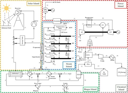
The devised system encompasses a concentrated solar plant (CSP), a biogas reformer, a steam network (SN), a hydrogen separation, a carbon capture and storage (CCS), a gas turbine cycle (GTC), and an organic Rankine cycle (ORC). The schematic of the proposed polygeneration system is illustrated in . In the proposed system, solar energy provides the required heat for the biogas reforming and the steam network; the produced syngas is utilised for hydrogen production, which is considered a promising clean fuel, along with heat and electricity. The description of the integrated system is elaborated below individually.
Figure 1. Schematic of the proposed hybrid polygeneration system.
2.1. Concentrated solar plant
A central receiver is utilised for absorbing the sun's radiation. The central receiver systems are capable of integration with various types of energy systems such as ORC and, therefore, are considered economically reasonable in comparison with parabolic trough collectors (PTC) technology (Schwarzbözl et al. Citation2000). To reflect the sun's radiation into the receiver, Heliostat field collectors (HFC), so-called power towers, are utilised, consisting of heliostat mirrors. Contrary to the common utilisation of water-steam, molten nitrate salt is used at the receiver in some cases. The single-phase state of molten salt enables the possibility to start the process faster, and besides, the molten salt has the advantage of being appropriate for storing heat.
In this study, the necessitated thermal energy for the reforming reactions and SN unit is provided by utilising a concentrated solar plant consisting of a receiver, heliostat fields, and a thermal storage unit. The heliostats track the solar rays, and then these rays are concentrated by utilising the molten salt cavity receiver located on the apex of the heliostat field. The generated high-temperature molten salt currents to the reformer (stream 18) provide the necessary heat for the reforming processes. The molten salt then leaves the reformer (stream 19). The exiting material is separated into two streams: one runs into the heater (stream 20) and increases the biogas-steam combination heat entering the reformer. Another stream flows to a steam generator (stream 21). The outlet streams of the heater (stream 22) and the steam generator (stream 23) are mixed, and then this stream enters the superheater and evaporator to provide the heat required for SN (stream 24). Lastly, the low-temperature molten salt completes this cycle by returning to the receiver (stream 25).
2.2. Biogas reformer
The biogas enters the pre-cooler (stream 1), and then high-temperature produced syngas from the reformer is utilised for heating it (stream 2). In stream 3, water at the surrounding temperature is mixed with condensed water from a gas–liquid separator (GLS) at stream 11. On the other side, the water is heated to steam by the molten salt in the steam generator (stream 5). Next, the produced steam is mixed with high-temperature biogas (stream 6). Then the exhausted molten salt (stream 20) is utilised for maintaining the suitable temperature of biogas in the reformer (stream 7). Biogas and water are employed to cool the generated high-temperature syngas (stream 8) in a pre-cooler and a cooler, respectively. The necessitated thermal energy for CO2 capturing through the CCS process is provided by the heat that is soaked up by water at stream 39. At stream 10, the low-temperature syngas currents to the GLS, where the condensate water is divided (stream 11). Afterward, the syngas with low-content H2O (stream 12) moves into the PSA and CCS correspondingly.
2.3. Steam network
In this study, the SN is integrated with three heat exchangers, including an economiser, an evaporator, and a superheater. The function of NG is to be used as a fuel to deliver the surplus amount needed by modular heat exchangers for steam production and heating. In the SN, four phases are passed for producing power and heat and steam supplement. Various steam turbines are utilised between each stage in order to generate power through the steam reduction process. The desuperheated steam is also extracted to be used for the heating process in utility centres. An steam reduction valve, which is a letdown process, can be utilised for adjusting the steam mass flow that is transferred between following stages.
2.4. Pressure swing adsorption
PSA technology has become common in many hydrogen-based industries because of its efficient and low-energy consumption. In this paper, a PSA unit is used for H2 separation from the syngas containing low amount of H2O (stream 12), which operates at ambient temperature and 1–4 bar pressure range. The separated H2 is then stored in a hydrogen storage tank (stream 13), and the rest flows to CCS (stream 14). This unit recovers Hydrogen content from syngas up to 85%. The cross-sectional area of this unit is 1.6 cm2, and according to literature, and its pressure drop is about 2.5% (Moon et al. Citation2018; Uehara Citation2008).
2.5. Carbon capture and sequestration
The syngas with low-content H2 from PSA is processed in the CCS to capture its CO2. The exploitation of the CCS unit in power plants has led to a considerable reduction of CO2 emissions. The H2 and CO2 free syngas are injected into the GTC (stream 16). The separated CO2 is compressed (stream 35) and stored (stream 36). The rest flows to GTC (stream 15). Based on previous work published in (Van-Dal and Bouallou Citation2013), The CCS unit utilised in this study uses monoethanolamine as a solvent with a mass concentration of 30%. Their results show that the rate of carbon dioxide capture of the devised module is about 85%, and energy consumption for feed compression is 44 kWhel per tons of CO2. Besides, the energy needed for is solvent regeneration 3200 kJ/kg of CO2, and the pressure drop occurring in this unit is around 5%.
2.6. Gas turbine cycle
In GTC, Inlet air is passed through an air compressor (AC), and then a recuperator is utilised for preheating this compressed air (stream 28). Leaving the CCS at stream 16, the unreacted syngas and hot air are led into a combustion chamber (CC) to be burned. After the CC, a gas turbine is devised to expand hot combustion gases for power production. Afterward, the high temperature flue gas is implemented for heating the compressed air in a recuperator (stream 30). The boiler feedwater (BFW) in the economiser (stream 31) is heated using this flue gas. Finally, the flue gas from the economiser (stream 32) flows to the ORC unit.
2.7. Organic Rankine cycle (ORC)
In this paper, a toluene-based organic ranking cycle (ORC) is used, which is integrated with an internal heat exchanger. This system has been used previously in a published work where a 31.5% energy efficiency is reported (Cao et al. Citation2016). The toluene of the ORC evaporator retrieves waste heat within flue gas exiting the economiser. The saturated vapor of the toluene is utilised for producing power through a turbine. Then a recuperator exploits the thermal energy of the toluene, which exits the turbine. Afterward, this energy is transported to the toluene stream, which is introducing into the evaporator.
3. Mathematical representation
In this study, the devised system is analyzed and evaluated from the energy and exergy efficiency points of view. The followings are the assumption used in this evaluation (Kolahi, Nemati, and Yari Citation2018; Pirmohamadi et al. Citation2021; Su, Han, and Jin Citation2017; Sun, Doyle, and Smith Citation2015):
A steady-state model is utilised for analyzing the units of the system.
Heat loss in the heat exchangers and pipelines are not considered valuable.
For steam turbines of the SN unit, a variable isentropic efficiency, corresponding to input loads, is considered.
Acid dew point at 120°C temperature is considered for flue gases leaving the GTC.
The pressure of deaerators is considered to be 1.208 bar, with saturated temperature.
The temperature in all subsystems of the SN is considered to be lower than 570
.
The value of pressure drops is considered 1% and 2% hot and cold sides, respectively.
Considering each component as control volumes, Mass and energy balances can be written as follows:
(1)
(1)
(2)
(2)
Also, the exergy destruction rate () is calculated with utilising an exergy balance:
(3)
(3) Where Ėxi is the ith component's exergy rate; this parameter can be divided into two parts: physical and chemical (Moran et al. Citation2010).
3.1. Solar System
In the solar tower of the devised system, a heliostat field is utilised. This heliostat field has consisted of several heliostats which their total aperture area () is used in the following relation for calculating concentrated solar energy of the tower (Tehrani and Taylor Citation2016):
(4)
(4) Subsequently, total indication absorbed energy is calculated using EquationEq. (5
(5)
(5) ).
(5)
(5) In case of the molten salt cavity receiver, the following relation describes its total energy balance. In this relation,
is the amout of energy absorbed by the receiver and
denotes for the total amount of heat losses:
(6)
(6)
includes losses such as conduction
, reflection
, radiation
, natural (
) and force convection (
). Tehrani and Taylor suggested the following relation for computing these heat losses (Tehrani and Taylor Citation2016):
(7)
(7) The relation between the receiver surface’ mean temperature
and the mean temperature of molten salt (
) can be also be shown by another relation (Tehrani and Taylor Citation2016), where, the areas of the receiver surface and aperture, and the total heliostat field area among the indeterminate parameters:
(8)
(8)
(9)
(9) Li et al. (Li et al. Citation2010) suggest that the classic Dittus–Boelter equation can be utilised for calculating the convective heat transfer coefficient of molten salt:
(10)
(10)
Which the following relation calculates Rems:
(11)
(11)
Also, the following relations are used for obtaining view factor (Fr) and the concentration ratio (Cr) that can be used to determine unknown factors.
(12)
(12)
(13)
(13)
(14)
(14)
The width of the receiver aperture is assumed (Tehrani and Taylor Citation2016). The absorbed receiver energy should provide the necessitated heat energy for biogas reforming. Therefore, the absorbed energy depends on the mass flowrate of molten salt and the inlet and outlet temperature of the reforming unit as follow:
(15)
(15) Therefore, the relation between several receiver tubes and molten salt flowrate is written as follow:
(16)
(16) By solving all of the above equations simultaneously, the unknown parameters such as areas, temperatures, molten salt flowrate, and the number of a receiver tube can be obtained.
In this work, the molten salt with the composition of KCl/MCl2 (62/38 w/w) is used as heat transfer fluid for the CST-tower unit (Binotti et al. Citation2017). This type of solar salt has high-temperature heat duty owing to its economy of cost, and thus no specific design for the receiver is needed (Binotti et al. Citation2017; Ho Citation2017). The required data for solar system modelling are listed in .
Table 1. The main parameter for the simulation of the CST-tower subsystem (Binotti et al. Citation2017; Mosaffa, Ghaffarpour, and Garousi Farshi Citation2019; Tehrani and Taylor Citation2016).
3.2. Solar biogas-steam reformer
Since the direct use of biogas in gas turbines and combustion engines is low-efficient and environmentally hazardous, an alternative method should be devised as a replacement for directly utilising biogas. Dry reforming (DSR), methane CO2 reforming, and methane steam (MSR) reforming are among the reforming process's main reactions. Enhancement of the efficiency of the process and the reduction in carbon formation can be achieved by combining the dry and steam reforming. There are also secondary reactions such as water gas shift (WGS), which are of high importance to produce enriched syngas and decrease CO2 greenhouse gas emission (Izquierdo et al. Citation2012). Equations of these reactions come in the following (Vita et al. Citation2018):
(17)
(17)
(18)
(18)
(19)
(19)
(20)
(20)
In this study, the chemical equilibrium composition is used for modelling the reformer. In order to do so, the temperature approach to equilibrium () is used, which is calculated by utilising reformer temperature
[28]. If we consider
and therefore
the obtained composition by the equilibrium model and kinetic model will be equivalent.
Configuring the equilibrium model for the reforming reactions is carried out by utilising the Gibbs free energy minimisation technique [28]. The relations of this technique are taken from Colpan et al. (Colpan, Dincer, and Hamdullahpur Citation2007).
The following relations are the equations for the molar flowrate in the reformer outlet:
(21)
(21)
(22)
(22)
(23)
(23)
(24)
(24)
(25)
(25)
(26)
(26)
In these relations, represent the extents of reactions shown in Eqs. (21-26), respectively.
Also, the equilibrium concentration of component elements at the expense of the reformer can be represented in the following:
(27)
(27) So, the chemical equilibrium equations of DSR, MSR, and WGS reactions are used for calculating the unknown parameters. In order to calculate these parameters, the following relations can be used:
(28)
(28)
(29)
(29)
(30)
(30)
The latter is calculated as:
(31)
(31) In these relations,
indicates the universal gas constant and
, and
are the standard enthalpy of formation, and Gibb's free energy in kJ kmol−1, respectively. demonstrates the key inputs for the biogas reformer (Su, Han, and Jin Citation2017).
3.3. Gas turbine cycle
The following reaction equation is used for utilising combustor based on combustion reaction with excess air:
(32)
(32) After the combustion chamber, a recuperator is devised which its function is preheating the air entering the combustion chamber. The following formula is employed for determining the exhaust temperature of the compressor (Taheri, Mosaffa, and Garousi Farshi Citation2017):
(33)
(33) Also, the flue gas temperature can be computed with the following formula:
(34)
(34) In these relations, ηis, GT represents the GTC isentropic efficiency, and γ means specific heat ratio. Consequently, the following relation is used for defining the net electrical power output of GTC:
(35)
(35) In this relation, ηG denotes the generator efficiency. contains vital input parameters to model the GTC.
Table 2. Required data for simulation of the biogas-steam reformer unit (Su, Han, and Jin Citation2017).
Table 3. Required data for simulating the GTC unit (Li and Yang Citation2021; Mosaffa, Ghaffarpour, and Garousi Farshi Citation2019; Su, Han, and Jin Citation2017).
3.4. Steam network modelling
3.4.1. Heat recovery unit
In this study, a series of heat exchangers, which provide the heating demand of the SN from different streams (Amiri, Sotoodeh, and Amidpour Citation2021). Therefore, the series is treated as a whole while describing the following concept. The principal function of HRSG is to retrieve heat from a gas turbine’ flue gases. Then, HRSG guides the retrieved heat to the water passing through the HRSG. In recovering the exhaust gases, additional amounts of fuel can also be injected into HRSG, making it work as a boiler.
For analyzing an HRSG unit, determining the thermodynamic specifications of the steam HRGS is a crucial step. GT inlet temperature, gas composition, acid dew point temperature of the gas, HRSG efficiency, the unit's operating pressure, and pinch point temperature of HRSG are among the variables necessitated for the properties as mentioned earlier. The saturated pressure of the deaerator is used for computing entering water temperature. In modelling an HRSG unit, the most crucial point that should be considered is avoiding a drop of the gas temperature exit below the acid dew point; because this incident can result in the deterioration of the equipment. The following relation is utilised for calculating the energy retrieved from the flue gases by an HRSG unit (Ahmadi and Dincer Citation2011):
(36)
(36) Where,
(37)
(37) In these relations,
means the thermal efficiency of the HRSG unit, and its presumed value is 90% (Ahmadi and Dincer Citation2011).
Injecting additional fuel into the unit is an appropriate option to increase entering gas temperature when all the necessitated steam cannot be covered entirely or the temperature needed for steam cannot be provided. Based on the mass flowrate of fuel and flue gas passed into the HRSG, the enthalpy of the superheater inlet gas can be utilised for determining the amount this necessitated extra fuel:
(38)
(38) Where
denotes for the duct burner (DB) efficiency, which is considered 93% (Ahmadi and Dincer Citation2011) and
is the gas mixture enthalpy.
3.4.2. Steam turbine
The following formula gives the steam flowrate entering a turbine at each level:
(39)
(39) With alterations of its mass flowrate, the steam turbine’ efficiency also changes. The highest efficiency of a steam turbine is achievable at the maximum flowrate (Varbanov, Doyle, and Smith Citation2004b). The overall efficiency of the devised steam network depends significantly on the variation of the steam turbine efficiency. Consequently, precise modelling of the steam turbine's flowrate variations is crucial in achieving an efficient cogeneration network. According to Ref. (Sun and Smith Citation2015), the following relation shows the connection between the maximum isentropic power and the shaft power at maximum load.
(40)
(40) Therefore, the efficiency of the steam turbine at maximum load can be calculated by the following relation:
(41)
(41) Maximum mass flowrate streaming through the steam turbine can be utilised for calculating steam turbine efficiency as the following relation presents (Sun and Smith Citation2015):
(42)
(42) Which a and b are calculated as follows,
(43)
(43)
(44)
(44) In the above relations,
and
are the inlet are the pressures of the entering and exiting steam, respectively. The relationship’s coefficients can be found in (Sun and Smith Citation2015).
Table 4. Necessary coefficients used in Eqs. (43-44) (Sun and Smith Citation2015).
3.4.3. Steam network targeting
Design parameters such as steam header pressures, initial efficiencies of the steam turbines, and the BFW and superheated temperatures for a system should be considered before starting the steam network modelling to guarantee accurate targeting. Also, instead of considering ideal efficiencies based upon steam turbine modelling relations, the steam turbine efficiency is estimated more accurately to increase targeting accuracy. Afterward, a steam network including steam headers, steam letdown station between every two headers, steam turbines, and steam consumption and generation units is devised in which the maximum power generation potential and maximum fuel consumption of the steam network is achieved (Sun, Doyle, and Smith Citation2015).
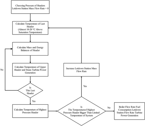
After developing the network, the system will have the maximised mass flowrate passing through each steam turbine. Consequently, the mass flowrate of steam from one steam header to another is presumed to vanish completely. By investigating power generation potential of the steam network, when it is functioning adequately, the fuel consumption can be appropriately targeted. Thereby, the system should be designed to set the mass flow variation in each header following the degree of superheating of each header. One of the harmful substances for blades of a turbine is moisture. By following this method, the emerging of moisture due to pressure drops in the pipes can be avoided to increase the system longevity. For this matter, the superheating of the last header must lead to the superheating of other headers. Consequently, the power production network targeting has two constraints: some superheating (10-20°C depending on the saturation temperature of the steam header) of the last steam header due to prevent saturation condition in above steam headers or having a specific mass fraction (about 10% of the vapor mass fraction) in the saturated liquid header (Smith Citation2005). Afterward, the last header upward is utilised for calculating the mass flowrate going through each turbine. In each header's targeting, the mass balance equation can be used to calculate the flowrate of steam passing from each turbine. The relation is as follows (Sun, Doyle, and Smith Citation2015):
(45)
(45) After calculation of the mass flowrate of steam passing through the turbine, the energy balance can be employed to the low-pressure header for determining the steam enthalpy at the outlet of a turbine (Sun and Smith Citation2015):
(46)
(46)
According to Ref. (Sun, Doyle, and Smith Citation2015), the specific enthalpy at the steam turbine’ outlet can be determined. After computing the maximum steam turbine efficiency by this formula:
(47)
(47) In order to find the specific enthalpy of the outlet of headers, the Iterative method can be utilised. After determining the specific enthalpy, the new header temperature should re-target steam consumption and achieve updated steam flowrate values. This process will be iterated until finding out the required information at all headers. Calculating the steam temperature at the very high-pressure steam header should not exceed the steam network system (570
). In the case of exceeding, the primary steam temperature must be revised. This revising consists of reducing the mass flowrate passing through the turbine and passing part of it through the letdowns. Following this method, steam is straight injected into headers from higher pressure ones and superheated. The trial-and-error approach should be used in this process until the fulfillment of the constraints. illustrates the targeting algorithm for the steam network.
Figure 2. Algorithm flowchart for steam network targeting for the proposed cogeneration system in the steam network (Amiri, Sotoodeh, and Amidpour Citation2021).
Some of the necessitated data for simulation of the steam network are listed in . Besides, shows the mass flue rate of steam produced and consumed by the site-wide utility.
Table 5. Key inputs for simulation of the steam network (Amiri, Sotoodeh, and Amidpour Citation2021; Sun, Doyle, and Smith Citation2015).
Table 6. Design considerations for the steam network simulation (Amiri, Sotoodeh, and Amidpour Citation2021; Sun, Doyle, and Smith Citation2015).
3.5. Key performance criteria
This study aims to propose a hybrid polygeneration system with carbon capturing and hydrogen production. Thus, other products in the system besides heat and power should be taken into account for computing efficiencies.
The energy efficiency of the standalone system as the topping cycle, which is not integrated with SN operated by biogas and solar energy, can be written as follows:
(48)
(48)
(49)
(49) Where LHV is lower heating value and W˙Net, standalone represents the standalone system's net power output.
The exergy efficiency for the standalone system can be described by the following formula:
(50)
(50) Where
is the domestic water heating (DWH) temperature which is delivered to the consumer (
according to Ref. (Su, Han, and Jin Citation2017)). Petela defines the exergy input fuel from solar radiation by this relation (Petela Citation2003):
(51)
(51)
in this relation represents the sun temperature, which is equal to 5505 °C, according to Ref. (Tehrani and Taylor Citation2016).
The energy efficiency of the proposed polygeneration system with CCS and hydrogen production fueled by biogas, solar energy, and natural gas can be defined as:
(52)
(52)
in EquationEq. (52
(52)
(52) ) is the net power and is stated as:
(53)
(53) In EquationEq. (52
(52)
(52) ), we have:
(54)
(54)
(55)
(55) Similarly, the exergy efficiency of the devised system is described as:
(56)
(56) Finally, the power/heating ratio for the cogeneration systems can be expressed as:
(57)
(57)
4. Model validation
In this study, the analyses are undertaken by developing and constructing mathematical models in Engineering Equation Solver (EES). The validity is evaluated by reviewing the existing data found in the literature. Due to the practical limitations, we compared our model with the existing mathematical and simulation results. To verify the model devised for the reformer, the predicted syngas composition is assessed with the available results (Su, Han, and Jin Citation2017) (see ). CST plant is validated based on the fixed receiver's outlet temperature strategy comparison in the present study and Ref. (Tehrani and Taylor Citation2016) (see ). From these results, it can be concluded that good correspondence is established between the model of this study and recent experimental data found in the literature.
Table 7. Verification of simulation results for the biogas reformer.
Table 8. Verification of simulation results for the CST-tower unit (Mosaffa, Ghaffarpour, and Garousi Farshi Citation2019).
Finally, the steam network simulation results are compared with Sun et al. (Sun, Doyle, and Smith Citation2015). The outcomes of this validation for mass flowrate and power are demonstrated in and , respectively. It can be concluded from this comparison that there is a good agreement.
Table 9. Verification of simulation results for the steam network based on mass flowrate calculations.
Table 10. Verification of simulation results for the steam network based on power calculation (Amiri, Sotoodeh, and Amidpour Citation2021).
5. Results and discussions
5.1. Modelling results
The proposed system outcomes, including the net power, heating load, steam generation, hydrogen production, and performance criteria, are indicated in . It can be suggested that using the SN increases energy efficiency by around 9% in comparison standalone multigeneration system. The devised system also produces a 218.175 MW amount of heat and 57.634 MW net electricity, making it a suitable option for polygeneration purposes. From the exergetic viewpoint, the most contribution to the exergy destruction of the system is the steam island by 1857.334 MW. By contrast, chemical and power islands have the lowest attribution to total exergy destruction, respectively. The results reveal an increase in exergy efficiency from 47.38% to 56.94% (). The obtained net electricity/heating ratio is 0.2642, which shows that the power generation still has superiority above heating despite surplus heating generated. shows the share of each island to the total exergy destruction.
Table 11. Final results obtained from simulation.
Table 12. Exergy destruction of each island (MW).
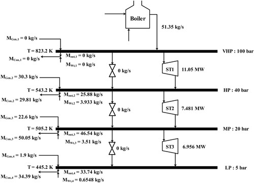
Furthermore, the results of the simulation for steam network targeting are illustrated in . In this simulation, it is assumed that the maximum steam temperature is 570. All determining parameters such as mass flowrate, temperature, pressure, and turbines’ output power are considered. It can be deduced from that the heat recovery unit has a steam consumption rate of 51.35 kg s−1, which is provided by products of steam turbines 1, 2, and 3 are 11.05, 7.481, and 6.956 MW, respectively. Consequently, 14.69 kg s−1 steam is generated.
Figure 3. Results of steam network targeting for maximum steam temperature.
5.2. Parametric study
In this sub-section, the impact of main parameters on the performance criteria and power/heat ratio, and overall exergy destruction rate is investigated through a parametric study. The considered paramount parameters include biogas flowrate, the reformer's operating conditions (Tr and Pr), and headers’ pressure in the steam island.
5.2.1. Biogas flowrate
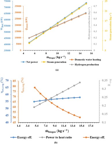
For this study, the biogas flowrate is varied from 5 kg s−1–15 kg s−1, while other parameters are fixed. a is represented in order to demonstrate the impact of on the subsystem outcomes. However, in a, different results are obtained by the increased flowrate, which also caused the exergy and energy efficiencies to increase eventually (b). Since the biogas flowrate rises, the exergy of fuel increases, resulting in more energy carriers. Accordingly, the net electricity of the power cycles increases by 86.6%. On the contrary, the net electricity of the steam network shows no alteration and remains constant. The reason is that the Qconsumption in the steam network is not dependent on
alterations. b also depicts the relation between net power/heat ratio and energy, exergy efficiencies. It can be concluded from this figure that with rising of the net power/heat ratio, energy efficiency declines exponentially and goes from 78.63% to 49.86%. The explanation could be as follows: when
increases, the input heat energy increases too -similar to output work, but as the ratio of input increase is higher, energy efficiency is lowered. Moreover, the exergy efficiency is increasing gently as
goes up while the overall exergy destruction rate increases at a higher pace since the exergy of fuel augments substantially, but the increment of exergy products is more appreciable. It should be noted that the amount of hydrogen and carbon capturing is twice more considerable after reaching 15 kg s−1 biogas flowrate, which subsequently resulted in a slight increase in the exergy efficiency.
Figure 4. Impact of the biogas flowrate on the: (a) net power, heating load, hydrogen, and steam generation and (b) performance criteria and net power/heat ratio.
5.2.2. Reformer temperature
For this part, the effect of the reformer temperature (Tr) on the system is inspected. For this matter, Tr is changed from 923 to 1173 K, while other parameters remain constant, and the outcomes are expounded (). In a, the influence of Tr on net power, heating load, steam, and hydrogen production rates is demonstrated, while the impact of Tr on performance criteria is depicted in b. It can be seen that Tr has a negative effect on net power and heat production. Increasing Tr results in a rising in the required thermal energy by biogas in the heater and molten salt's mass flowrate. Therefore, more steam is generated by the steam island.
Figure 5. Impact of the reformer temperature on the: (a) net power, heating load, hydrogen and steam generation, and (b) performance criteria and net power/heat ratio.
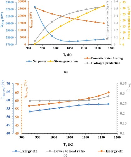
On the other hand, under the given circumstances, the total system's heat duty declines nearly due to reducing carbon-capturing in the chemical island. In this temperature range, output power decreases by 17.2%. The generated heat for heating purposes declines by about 42.5%, resulting in a decrease in net power/heat ratio (b). It can be understood from b that the exergy efficiency is almost unvaried (□53-58%) while energy efficiency is increasing (□57-65%), which is a result of the molten salt flowrate increment due to the augmentation of the heat transfer irreversibility.
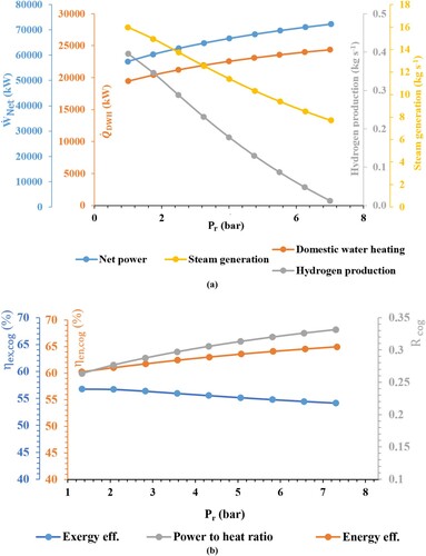
5.2.3. Reformer pressure
For analyzing the impact of the reformer pressure (Pr) on the subsystem outcomes and polygeneration performance indicators, Pr is increased from 1 to 7 bar, while other parameters have remained unvaried (). Because of the increase in Pr, the generated power of the cycles increases by 28.4%. Besides, in the meantime, carbon capturing increases considerably, while hydrogen production decreases by about 31.4%. b shows the influence of Pr on the performance indicators and power to heat ratio. As is seen in this figure, when the pressure of the reformer goes up, the exergy efficiency decreases smoothly from 57% to 54% due to the rapid reduction of hydrogen production and steam generation.
Figure 6. Impact of the reformer pressure on the: (a) net power, heating load, hydrogen and steam generation, and (b) performance criteria and net power/heat ratio.
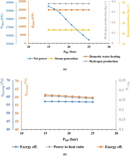
5.2.4. Steam network medium pressure
a shows the alterations of subsystem outcomes as the PMP increases from 15 bar to 25 bar. Accordingly, net power output is greatly affected by PMP since the turbine located on the steam island produces less work as pressure goes up. Based on analyzing b, it can be concluded that with increasing PMP, both the energy efficiency and net power/heat ratio are decreased while the exergy is not affected considerably. Accordingly, by increasing PMP from 15 bar to 25 bar, the net power/heat ratio is reduced and goes from 0.269–0.257. The following reasons can describe these trends. When PMP is increased, expansion ratios of upper turbines decrease, and therefore the power of steam turbines and heating load is lowered. This process results in a decrease in energy efficiency and Rcog because of the higher net electricity role.
Figure 7. Impact of the steam network medium pressure on the: (a) net power, heating load, hydrogen and steam generation, and (b) performance criteria and net power/heat ratio.
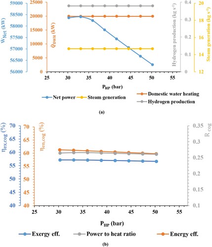
5.2.5. Steam network high pressure
The impact of the steam network high pressure on subsystem results and polygeneration performance criteria can be deduced from . a shows a slight increase around the peak before the tail. As PHP increases, the output work produced by ST1 and ST2 is changing. Since the ST2 flowrate is greater than the flowrate of ST3, the rate of power increment in ST2 will be higher than the rate of power reduction in ST3, resulting in a positive change at the beginning, as shown in a. Based on b, an increase in PHP results in a slight decrease in energy and exergy efficiencies. Similar to the medium pressure in the header, the following reasons can be enumerated for such trends. As PHP rises, steam turbines’ power decreases along with the heating load; accordingly, the net power/heating ratio declines.
Figure 8. Impact of the steam network high pressure on the: (a) net power, heating load, hydrogen and steam generation, and (b) performance criteria and net power/heat ratio.
5.2.6. Steam network very high pressure
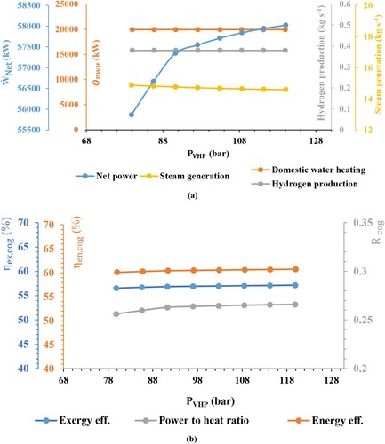
depicts the impact of the steam network's very high pressure (PVHP) on subsystem outcomes and performance indicators. Similar to the PHP, the ST1 power increases with the augmentation of pressure level, but since the turbine efficiency varies depending on the turbine's capacity, a trend with different slopes is resulted (a). It can be concluded from b that first and second law efficiencies are enhanced with the increase of PVHP. It is worthy of pinpointing that the heating load and power of GTC and ORC units have remained unvaried through this analysis, and hence the trend of the net electricity of the devised polygeneration system, and also energy efficiency will follow that of the steam turbines power.
Figure 9. Impact of the steam network very high pressure on the: (a) net power, heating load, and hydrogen and steam generation, and (b) performance criteria and net power/heat ratio.
5.3. Optimisation
An optimisation investigation can be useful to promote the efficiency of the proposed layout. Since the optimal system design is a complex process, conventional optimisation methods have failed to be either efficient or accurate; therefore, many new optimisation methods based on Artificial Intelligence (AI) have been developed to find the global optimal with fast convergence and good accuracy (Kolahi, Amidpour, and Yari Citation2020; Ranjbar, Nemati, and Kolahi Citation2018). Genetic algorithms have more advantages in feature band selection, small sample size classification, and classification accuracy than the other group intelligence algorithms (e.g. artificial bee colony and particle swarm optimisation) (Zhu, Li, and Pan Citation2019). Many optimisation algorithms are performed in hybrid systems analyses; however, GAs have proven to be a robust optimisation technique that denotes the ability of the GAs for finding the global optimum, or a near-optimal point, for any optimisation problem (Mohsenipour et al. Citation2019). For instance, Li and Yang (Li and Yang Citation2021) compared some optimisation methods for a hybrid energy system. They showed that the genetic algorithm performs better than the other algorithms (particle swarm optimisation and evolutionary algorithm based on decomposition) and provides the most approximate accurate Pareto solutions. For this matter, a Genetic algorithm is employed in order to locate the optimum value for exergy efficiency. The assumptions of the Genetic Algorithm Optimisation are shown in (Rostamzadeh et al. Citation2018).
Table 13. Optimisation assumptions and settings for the Genetic algorithm.
The results of optimisation, including the design parameters and key outcomes, are demonstrated in .
Table 14. Comparison of optimisation and base case.
6. Conclusions
In this study, an innovative polygeneration energy system based on biogas and solar energy is proposed. This system is also devised for hydrogen concurrently benefited from a carbon capture unit and heat and power generation for meeting the necessitated energy. A site-wide utility is integrated with the solar island to use the surplus heat returning to the receiver. To produce the steam needed in the steam island, NG is utilised as a primary fuel. Solar thermal energy, absorbed by a CTS-tower plant, is utilised in the processes, which are taken place in the reformer. The necessitated heat for steam is made available through these processes. Furthermore, CCS and PSA separate the CO2 and H2 contents of the produced syngas, respectively. In this study, the energetic and exergetic analyses are carried out on the devised system. Afterward, the foremost parameters of subsystems are analyzed, and then an optimisation study is performed. The conclusive remarks can be drawn as follows:
The efficiency is increased from 51.72% to 60.55% by integrating the steam network system with the topping system. This integration also led to about a 9.5% increase in exergy efficiency.
Consequently, an increase from 32.147 MW to 57.634 MW is observed in the net power.
A decrease in CO2 conversion is visible when the reformer temperature is increased.
As the reformer pressure rose, overall net power output and captured carbon dioxide increase, respectively.
Adjusting the reformer pressure design is a solution for maximising the net power/heat ratio.
These alterations boost the devised system efficiency: decreasing biogas flowrate, reformer temperature, medium, and high-pressure headers. Also, increasing reformer pressure and PVHP of the steam island increases energy efficiency.
Decreasing biogas flowrate, reformer temperature, and also increasing reformer temperature enhance the exergy efficiency. On the other hand, the pressure headers in the steam island unit do not have a considerable effect on exergy efficiency.
The optimisation’ results report 58.06% for exergy efficiency under optimal inputs, which also increases energy efficiency from 60.55% to 65.94%.
Different suggestions could be made based on the devised system of the current study:
At first, due to the implemental limitations, the current scheme has not been found in a real complex based on the authors’ knowledge. This system can be integrated with petrochemical clusters for satisfying the steam demand of different processes; thus, the feasibility of this system coupled with existing process infrastructures can be a matter of future research.
Secondly, hydrogen and carbon dioxide can be implemented in a methanol synthesis unit, which can be an excellent approach for using CO2 efficiently. Thirdly, a thermo-economic evaluation of the subsystems and primarily the SN and CTS-Tower, which are the most expensive ones, could enhance the system and make it more feasible. In this study, parameters such as efficiencies of turbines, pumps, and compressors of the topping cycle are assumed to be unvaried. Another suggestion for further studies is to vary these parameters to have a better sense of the optimal operation.
Disclosure statement
No potential conflict of interest was reported by the author(s).
References
- Ahmadi, Pouria, and Ibrahim Dincer. 2011. “Thermodynamic Analysis and Thermoeconomic Optimization of a Dual Pressure Combined Cycle Power Plant with a Supplementary Firing Unit.” Review of. Energy Conversion and Management 52 (5): 2296–2308.
- Akri, Mohcin, Ouafae Achak, Pascal Granger, Sheng Wang, Catherine Batiot-Dupeyrat, and Tarik Chafik. 2018. “Autothermal Reforming of Model Purified Biogas Using an Extruded Honeycomb Monolith: A new Catalyst Based on Nickel Incorporated Illite Clay Promoted with MgO.” Review of. Journal of Cleaner Production 171: 377–389.
- Amiri, Hamed, Amir Farhang Sotoodeh, and Majid Amidpour. 2021. “A new Combined Heating and Power System Driven by Biomass for Total-Site Utility Applications.” Review of. Renewable Energy 163: 1138–1152. doi:https://doi.org/10.1016/j.renene.2020.09.039.
- Bianchini, Augusto, Marco Pellegrini, and Cesare Saccani. 2015. “Solar Steam Reforming of Natural gas Integrated with a gas Turbine Power Plant: Economic Assessment.” Review of. Solar Energy 122: 1342–1353. doi:https://doi.org/10.1016/j.solener.2015.10.046.
- Binotti, Marco, Marco Astolfi, Stefano Campanari, Giampaolo Manzolini, and Paolo Silva. 2017. “Preliminary Assessment of sCO2 Power Cycles for Application to CSP Solar Tower Plants.” Review of. Energy Procedia 105: 1116–1122.
- Cao, Yue, Yike Gao, Ya Zheng, and Yiping Dai. 2016. “Optimum Design and Thermodynamic Analysis of a gas Turbine and ORC Combined Cycle with Recuperators.” Review of. Energy Conversion and Management 116: 32–41.
- Colpan, C Ozgur, Ibrahim Dincer, and Feridun Hamdullahpur. 2007. “Thermodynamic Modeling of Direct Internal Reforming Solid Oxide Fuel Cells Operating with Syngas.” Review of. International Journal of Hydrogen Energy 32 (7): 787–795.
- Darvell, L.I., J.M. Jones, B. Gudka, X.C. Baxter, A. Saddawi, A. Williams, and A. Malmgren. 2010. “Combustion Properties of Some Power Station Biomass Fuels.” Review of. Fuel 89 (10): 2881–2890.
- Ebadollahi, Mohammad, Hadi Rostamzadeh, Mona Zamani Pedram, Hadi Ghaebi, and Majid Amidpour. 2019a. “Proposal and Assessment of a new Geothermal-Based Multigeneration System for Cooling, Heating, Power, and Hydrogen Production, Using LNG Cold Energy Recovery.” Review of. Renewable Energy 135: 66–87. doi:https://doi.org/10.1016/j.renene.2018.11.108.
- Ebadollahi, Mohammad, Hadi Rostamzadeh, Mona Zamani Pedram, Hadi Ghaebi, and Majid Amidpour. 2019b. “Proposal and Multi-Criteria Optimization of two new Combined Heating and Power Systems for the Sabalan Geothermal Source.” Review of. Journal of Cleaner Production 229: 1065–1081. doi:https://doi.org/10.1016/j.jclepro.2019.05.022.
- Ebadollahi, Mohammad, Hadi Rostamzadeh, Omid Pourali, Hadi Ghaebi, and Majid Amidpour. 2021. “Close Supercritical Versus Inverse Brayton Cycles for Power Supply, Using Waste of a Biogas-Driven Open Brayton Cycle.” Review of. J Journal of Energy Resources Technology 143 (9): 092102.
- Ebadollahi, Mohammad, Hadi Rostamzadeh, Pourya Seyedmatin, Hadi Ghaebi, and Majid Amidpour. 2020. “Thermal and Exergetic Performance Enhancement of Basic Dual-Loop Combined Cooling and Power Cycle Driven by Solar Energy.” Review of. Thermal Science and Engineering Progress 18: 100556. doi:https://doi.org/10.1016/j.tsep.2020.100556.
- Farjana, Shahjadi Hisan, Nazmul Huda, M.A. Parvez Mahmud, and R. Saidur. 2018. “Solar Industrial Process Heating Systems in Operation – Current SHIP Plants and Future Prospects in Australia.” Review of. Renewable and Sustainable Energy Reviews 91: 409–419. doi:https://doi.org/10.1016/j.rser.2018.03.105.
- Gargari, Saeed Ghavami, Mostafa Rahimi, and Hadi Ghaebi. 2019. “Energy, Exergy, Economic and Environmental Analysis and Optimization of a Novel Biogas-Based Multigeneration System Based on Gas Turbine-Modular Helium Reactor Cycle.” Review of. Energy Conversion and Management 185: 816–835. doi:https://doi.org/10.1016/j.enconman.2019.02.029.
- Ho, Clifford K. 2017. “Advances in Central Receivers for Concentrating Solar Applications.” Review of. Solar Energy 152: 38–56.
- Ishaq, H., and I. Dincer. 2019. “Exergy Analysis and Performance Evaluation of a Newly Developed Integrated Energy System for Quenchable Generation.” Review of. Energy 179: 1191–1204. doi:https://doi.org/10.1016/j.energy.2019.05.050.
- Iulianelli, A., S. Liguori, Y. Huang, and A. Basile. 2015. “Model Biogas Steam Reforming in a Thin Pd-Supported Membrane Reactor to Generate Clean Hydrogen for Fuel Cells.” Review of. Journal of Power Sources 273: 25–32.
- Izquierdo, U., V.L. Barrio, N. Lago, J. Requies, J.F. Cambra, M.B. Güemez, and P.L. Arias. 2012. “Biogas Steam and Oxidative Reforming Processes for Synthesis gas and Hydrogen Production in Conventional and Microreactor Reaction Systems.” Review of. International Journal of Hydrogen Energy 37 (18): 13829–13842.
- Johnson, Ilona, William T. Choate, and Amber Davidson. 2008. Waste Heat Recovery. Technology and Opportunities in U.S. Industry. United States. https://doi.org/https://doi.org/10.2172/1218716
- Jouhara, H., N. Khordehgah, S. Almahmoud, B. Delpech, A. Chauhan, and S.A. Tassou. 2018. “Waste Heat Recovery Technologies and Applications.” Review of. Thermal Science and Engineering Progress 6: 268–289. doi:https://doi.org/10.1016/j.tsep.2018.04.017.
- Kasaeian, Alibakhsh, Parisa Rahdan, Mohammad Amin Vaziri Rad, and Wei-Mon Yan. 2019. “Optimal Design and Technical Analysis of a Grid-Connected Hybrid Photovoltaic/Diesel/Biogas Under Different Economic Conditions: A Case Study.” Review of. Energy Conversion and Management 198: 111810. doi:https://doi.org/10.1016/j.enconman.2019.111810.
- Khan, Jibran, and Mudassar H Arsalan. 2016. “Solar Power Technologies for Sustainable Electricity Generation–A Review.” Review of. Renewable and Sustainable Energy Reviews 55: 414–425.
- Kolahi, Mohammad-Reza, Majid Amidpour, and Mortaza Yari. 2020. “Multi-objective Metaheuristic Optimization of Combined Flash-Binary Geothermal and Humidification Dehumidification Desalination Systems.” Review of. Desalination 490: 114456.
- Kolahi, Mohammad-Reza, Arash Nemati, and Mortaza Yari. 2018. “Performance Optimization and Improvement of a Flash-Binary Geothermal Power Plant Using Zeotropic Mixtures with PSO Algorithm.” Review of. Geothermics 74: 45–56. doi:https://doi.org/10.1016/j.geothermics.2018.02.004.
- Li, Xin, Weiqiang Kong, Zhifeng Wang, Chun Chang, and Fengwu Bai. 2010. “Thermal Model and Thermodynamic Performance of Molten Salt Cavity Receiver.” Review of. Renewable Energy 35 (5): 981–988.
- Li, Rong, and Yong Yang. 2021. “Multi-objective Capacity Optimization of a Hybrid Energy System in two-Stage Stochastic Programming Framework.” Review of. Energy Reports 7: 1837–1846.
- Madvar, Mohammad Dehghani, Farzin Ahmadi, Reza Shirmohammadi, and Alireza Aslani. 2019. “Forecasting of Wind Energy Technology Domains Based on the Technology Life Cycle Approach.” Review of. J Energy Reports 5: 1236–1248.
- Mohsenipour, Mahmoud, Farzin Ahmadi, Amir Mohammadi, Mohammad Ebadollahi, and Majid Amidpour. 2019. “Investigation of a Geothermal-Based CCHP System from Energetic, Water Usage and CO2 Emission Viewpoints.” Review of. Gas Processing Journal 7 (1): 41–52. doi:https://doi.org/10.22108/gpj.2019.118131.1058.
- Moon, Dong-Kyu, Yongha Park, Hyun-Taek Oh, Shin-Hyuk Kim, Min Oh, and Chang-Ha Lee. 2018. “Performance Analysis of an Eight-Layered bed PSA Process for H2 Recovery from IGCC with pre-Combustion Carbon Capture.” Review of. Energy Conversion and Management 156: 202–214.
- Moran, Michael J, Howard N Shapiro, Daisie D Boettner, and Margaret B Bailey. 2010. Fundamentals of Engineering Thermodynamics. New York: John Wiley & Sons.
- Mosaffa, A.H., Z. Ghaffarpour, and L. Garousi Farshi. 2019. “Thermoeconomic Assessment of a Novel Integrated CHP System Incorporating Solar Energy Based Biogas-Steam Reformer with Methanol and Hydrogen Production.” Review of. Solar Energy 178: 1–16. doi:https://doi.org/10.1016/j.solener.2018.12.011.
- Ozturk, Murat, and Ibrahim Dincer. 2013. “Thermodynamic Assessment of an Integrated Solar Power Tower and Coal Gasification System for Multi-Generation Purposes.” Review of. Energy Conversion and Management 76: 1061–1072.
- Pérez-Uresti, Salvador I, Mariano Martín, and Arturo Jiménez-Gutiérrez. 2019. “Estimation of Renewable-Based Steam Costs.” Review of. J Applied Energy 250: 1120–1131.
- Petela, Richard. 2003. “Exergy of Undiluted Thermal Radiation.” Review of. Solar Energy 74 (6): 469–488.
- Pirmohamadi, Alireza, Hadi Ghaebi, Behrooz M. Ziapour, and Mohammad Ebadollahi. 2021. “Exergoeconomic Analysis of a Novel Hybrid System by Integrating the Kalina and Heat Pump Cycles with a Nitrogen Closed Brayton System.” Review of. Energy Reports 7: 546–564. doi:https://doi.org/10.1016/j.egyr.2021.01.009.
- Ranjbar, Seyed Faramarz, Arash Nemati, and Mohammad Reza Kolahi. 2018. “Thermodynamic Analysis and Improvement of a Flash/ORC Geothermal Plant Using ZeotropicMixtures as Working Fluids in ORC.” Review of. Journal of Mechanical Engineering 48 (2): 131–138.
- Rostamzadeh, Hadi, Keivan Mostoufi, Mohammad Ebadollahi, Hadi Ghaebi, and Majid Amidpour. 2018. “Exergoeconomic Optimisation of Basic and Regenerative Triple-Evaporator Combined Power and Refrigeration Cycles.” Review of. International Journal of Exergy 26 (1-2): 186–225.
- Schwarzbözl, Peter, Robert Pitz-Paal, Wolfgang Meinecke, and Reiner Buck. 2000. Cost-Optimized Solar Gas Turbine Cycles Using Volumetric Air Receiver Technology. Paper presented at the Proc. 10th SolarPACES Int. Symp. Solar Thermal 2000.
- Smith, Robin. 2005. Chemical Process: Design and Integration. I Chichester, West Sussex, United Kingdom: John Wiley & Sons.
- Su, Bosheng, Wei Han, and Hongguang Jin. 2017. “Proposal and Assessment of a Novel Integrated CCHP System with Biogas Steam Reforming Using Solar Energy.” Review of. Applied Energy 206: 1–11.
- Sun, Li, Steve Doyle, and Robin Smith. 2015. “Heat Recovery and Power Targeting in Utility Systems.” Review of. Energy 84: 196–206. doi:https://doi.org/10.1016/j.energy.2015.02.087.
- Sun, Li, and Robin Smith. 2015. “Performance Modeling of new and Existing Steam Turbines.” Review of. Industrial & Engineering Chemistry Research 54 (6): 1908–1915.
- Taheri, M.H., A.H. Mosaffa, and L. Garousi Farshi. 2017. “Energy, Exergy and Economic Assessments of a Novel Integrated Biomass Based Multigeneration Energy System with Hydrogen Production and LNG Regasification Cycle.” Review of. Energy 125: 162–177.
- Tehrani, S Saeed Mostafavi, and Robert A Taylor. 2016. “Off-design Simulation and Performance of Molten Salt Cavity Receivers in Solar Tower Plants Under Realistic Operational Modes and Control Strategies.” Review of. Applied Energy 179: 698–715.
- Uehara, Itsuki. 2008. “Separation and Purification of Hydrogen.” Review of. Energy Carriers and Conversion Systems with Emphasis on Hydrogenvol 1: 268–282.
- Van-Dal, Éverton Simões, and Chakib Bouallou. 2013. “Design and Simulation of a Methanol Production Plant from CO2 Hydrogenation.” Review of. Journal of Cleaner Production 57: 38–45.
- Varbanov, P.S., S. Doyle, and R. Smith. 2004a. “Modelling and Optimization of Utility Systems.” Review of. Chemical Engineering Research and Design 82 (5): 561–578. doi:https://doi.org/10.1205/026387604323142603.
- Varbanov, P.S., S. Doyle, and R. Smith. 2004b. “Modelling and Optimization of Utility Systems.” Review of. Chemical Engineering Research and Design 82 (5): 561–578.
- Velasco-Garcia, Patricia, Petar Sabev Varbanov, Harvey Arellano-Garcia, and Günter Wozny. 2011. “Utility Systems Operation: Optimisation-Based Decision Making.” Review of. Applied Thermal Engineering 31 (16): 3196–3205. doi:https://doi.org/10.1016/j.applthermaleng.2011.05.046.
- Vita, A., C. Italiano, D. Previtali, C. Fabiano, A. Palella, F. Freni, G. Bozzano, L. Pino, and Fabio Manenti. 2018. “Methanol Synthesis from Biogas: A Thermodynamic Analysis.” Review of. Renewable Energy 118: 673–684.
- Yu, Aofang, Wen Su, Xinxing Lin, and Naijun Zhou. 2020. “Recent Trends of Supercritical CO2 Brayton Cycle: Bibliometric Analysis and Research Review.” J Nuclear Engineering and Technology 53 (3): 699–714.
- Zheng, R., Y. Zhang, X. Yu, Z. He, S. Dong, B. Li, H. Wang, and M. Lv. 2017. “Experimental Research and Feasibility Analysis of Low-Temperature Power Generation Systems Used in Petrochemical Industry.” Review of. Journal of Energy Engineering 143 (3), doi:https://doi.org/10.1061/(ASCE)EY.1943-7897.0000412.
- Zhu, Xiufang, Nan Li, and Yaozhong Pan. 2019. “Optimization Performance Comparison of Three Different Group Intelligence Algorithms on a SVM for Hyperspectral Imagery Classification.” Review of. Remote Sensing 11 (6): 734.